by TMY Editorial Staff
Materials:
- Piece of cardboard (the back of a tablet)
- Pencil
- Fairing stick
- Scissors
- X-ACTO® knife
- Straight edge
This method of developing a pattern for the deck beams on your boat should work for most boats. A deck should have a crown (camber) ranging from 1/8 in to 1⁄4 in at the widest part of the hull to allow water to run off the deck. Most decks curve from bow to stern and from port to starboard. Generally, the fore to aft curve is upward at the ends and the port to starboard curve is downward at the edges. Check your plan and see if there are two lines from stem to stern on the boat’s profile. One is the sheer line (edge of deck), and the other is the top of the deck at the center of the boat. Some plans have these two lines, and others have only the sheer line.
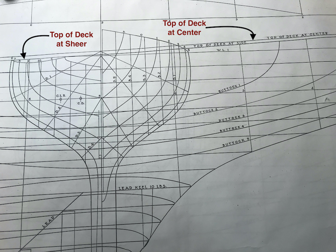
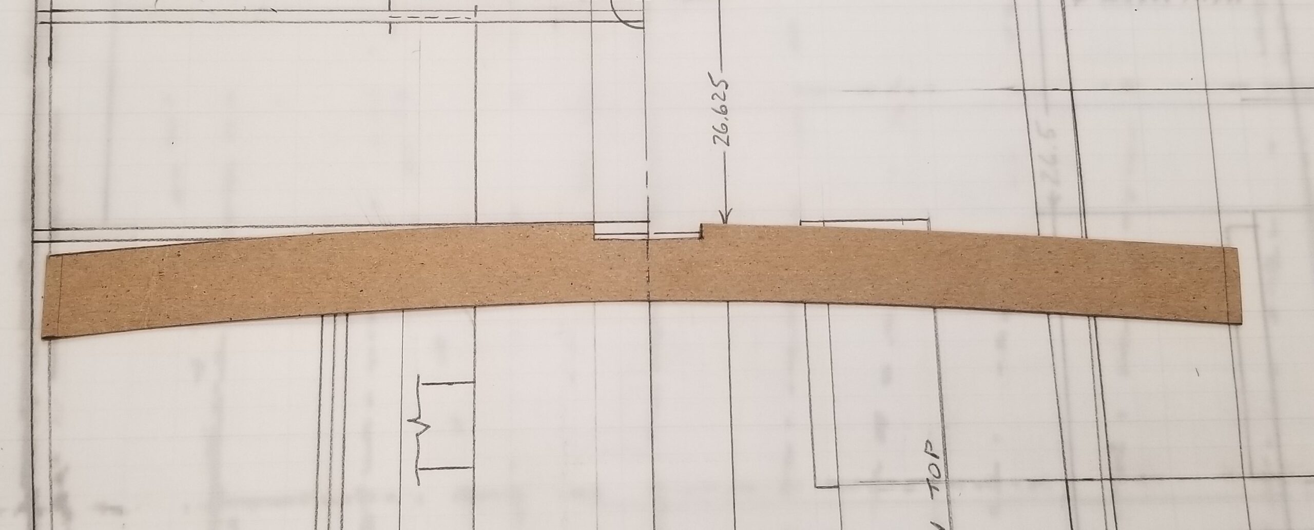
If your plan has the two lines measure the vertical difference between the two lines at the widest point of the boat. This will become “X” in the discussion below. If you do not have the two lines on your plan, then you will have to determine that dimension (X). If you look closely at the plan below, you can see these two lines.
Note that, at least in this design, both the sheer line and the deck centerline are higher at the ends of the boat than in the midships sections. This means that a deck made of sheet material (such as plywood) must curve simultaneously in two directions – i.e., we are forcing it into a compound curve. Sheet material resists this. (Try bending a sheet of paper simultaneously up fore-and-aft at the ends and down at the sides.) Over some limited bending range, you can “torture” plywood into shape. Beyond this range, it is likely to form some kind of non-fair inflection. Before making a full set of deck beams, it might be worthwhile to experiment with the candidate deck beam camber. You may find that raising or lowering the deck centerline may allow the plywood to assume shape more easily. For example, a deck with camber adjusted so that the deck centerline forms a straight line from the top of the stem to the top of the transom will not require compound bending.
This process will ensure that all of the deck beams have the same proportions of this curve (camber) from bow to stern.
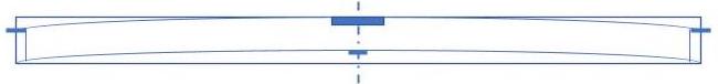
- Draw a rectangle that is as long as the longest deck beam on your boat (measure to the outside edge of the hull at the deck beam location) and with a height of 3⁄4 in plus the height you would like the center of the deck (let us call it “X”) to be above the outside edge of the deck. Place a vertical center line through the rectangle.

- Mark down “X” at each edge and up “X” on the centerline. “X” is either the dimension you pulled off of the plan or the dimension you chose.
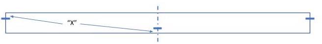
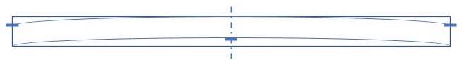
- Use a fairing stick to draw an arc from the upper left mark through the top center to the upper right mark. Draw an identical arc from the lower left corner through the mark on the center line and to the lower right-hand corner.
- Mark an area, dead center at the top of the pattern, 1⁄8 by 1 in, for the king plank notch.
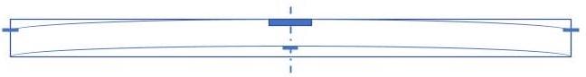
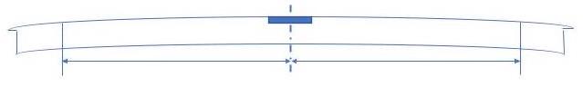
- Measure the length of the longest beam (on the plan) from the inside edge of the sheer clamp on the port to the inside edge of the sheer clamp on the starboard side. Split this dimension in half. Measure out that amount from the centerline of the template and draw a vertical line on each side that intersects the upper mark at each edge of the template.
- Cut this out using scissors and an X-ACTO knife.
You now have the template for the longest deck beam. It will be used for laying out all of your deck beams. DO NOT CUT THIS TEMPLATE DOWN!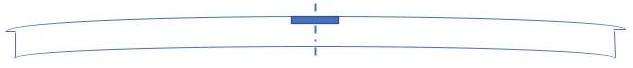
- Now trace the template onto the piece of wood you will be using for your deck beams.
- Using the same template, trace the next beam on the wood – mark the center line. Measure the beam length from the inside of the sheer clamp on one side of the boat to the inside of the sheer clamp on the other side. Divide this in half and measure out that amount on each side for the new beam and place vertical lines at those locations.
- Redraw the notches at the ends of the beam.
- Repeat the process until all of the deck beams are cut to size. Cut the beams out and check each for fit as you proceed.
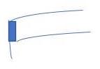
There are different ways to prepare the ends of the deck beams (see the examples) and fit them into place at the intersection of the beam and the sheer clamp. Only one method has been described here. Whichever method you chose, you will need to fair them in along the top edges of the beams, king plank, sheer clamp, and sheer strake using a flexible sanding board. This ensures that the deck touches all of these surfaces when you glue it in place. This sanding board can be made from a 4- by 15-in (approximate) piece of 1/16-in plywood with adhesive-backed sandpaper (120 grit) adhered to it.
This sanding board will flex very easily and can be used to sand down the high spots on the deck beams, king plank, sheer strake, and sheer clamp. You can actually see the areas abrade as you sand them by flexing the sanding aboard while you move along the top edges. If you are having trouble detecting the areas that are being abraded, take a pencil and mark all of the top edges. As you sand the pencil markings will be removed. Sand until they are all gone. The goal here is to get all of these surfaces to blend into one continuous curved surface.
NOTES:
- The deck crown height is dependent on the length of a boat. A 36-in boat should have a crown of ~1⁄8 in while a 50-in boat should have a crown of ~1⁄4 in. The appearance can necessitate making the crown higher or lower depending on how the resultant curve looks. Of course, larger boats would need more of a crown. Increasing these numbers will increase the potential of a non-fair deck surface.
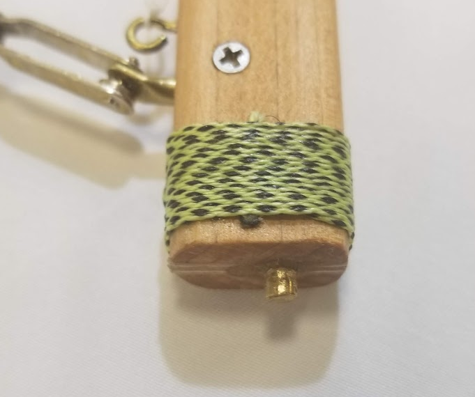
- A fairing stick is used to “fair in” curves in the boat building process. For model yachts, a 3/16- by 3/16-in piece of straight grained hardwood makes a very nice fairing stick. Make them about 6 ft long.