Article, photo, and illustrations by John Henderson
The heaviest single component, by far, in our models is the ballast. Typically, the ballast is at least 60% of the total weight, unless forbidden by class rules (e.g., the Skipjack 48). If the boat is to float level, this ballast must be in the right place, and the position can be found simply, without arithmetic computations. As will be explained, the ballast position can be determined early in the building process, when it can be planned into the structure, and it can be accomplished even before the hull is waterproofed and floated.
An alternative to the mildly analytical techniques described in this note—and a common practice in modeling—is to float the hull in a pool and adjust the ballast in both amount and location until the boat floats level on its waterline. (Of course, you need a pool that is big enough and deep enough, and I have found that a bathtub rarely works.) But waiting until the hull is finished before determining exactly where and how big its major weight component is risks surprises and makes it less likely that the hull structure will be optimum. We can and should plan the ballast much earlier in the build process. Planning also minimizes the need for “trim” ballast, inserted at the last minute to “correct” a problem that was avoidable. Trim ballast adds weight and increases the pitching moment, because the trim ballast is likely located in the ends of the boat.
If building from plans and following them exactly, the amount and position of the ballast is probably indicated reliably. But what if we are scaling the plans to a different size—perhaps by building a scale model of an existing full-size boat or by transforming a favorite design to a larger or smaller class (e.g., a Vintage Marblehead to a Vintage 36, or vice versa)? Maybe we want to change the keel to make it deeper (as the AMYA J-Class does), have a more vertical leading edge, or have a different profile in the trailing edge. Maybe we want to move the rudder or make it bigger. Any of these changes has the potential to require re-examination of the location of the ballast. Additionally, and especially in full-keel models, the deepest part of the keel may not be where the ballast must be placed. The starting point is the location of the Longitudinal Center of Buoyancy of the hull. This is (almost) always shown on the plans as either “LCB” or perhaps just “CB”. This is, basically, the center of the underwater volume of the hull. (If necessary, the LCB can be calculated as a simple extension of the calculation of displacement; these two computations may be the subject of a future “Tech Topic”.)
The LCB can be thought of as the fore-and-aft place where the flotation forces are concentrated. In a sense, it is analogous to the more familiar concept of Center of Gravity.
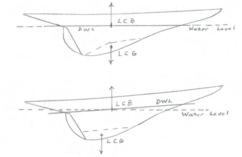
If the boat is to float level, its Longitudinal Center of Gravity (LCG) must be at the same fore-aft location as the LCB. I think this is intuitive, but a few explanatory words: The weight of the boat is pulling downwards, and the location of this force is at the LCG. The buoyancy of the boat is pushing upwards, and the location of this force is at the LCB. If the LCG is aft of the LCB, the boat will be down at the stern; an LCG forward of the LCB puts the bow down. See Fig. 1, where the ballast is located within the dashed lines deep in the keel. The first sketch shows the ballast located correctly to put the LCG below the LCB, and so the designed waterline (DWL) is level. The second sketch shows a ballast location that puts the LCG aft of the LCB; the designed waterline (DWL) is no longer level, and the boat floats bow-high. Note that this incorrect ballast location, for a hull profile shape such as the one drawn in the figure, actually puts the ballast lower. Lower ballast might be tempting for stability, but stability cannot be achieved at the expense of floating level.
Since we know the location of the LCB from the design drawings, and we know that the LCG must be located at the same fore-aft position, we can use this knowledge to locate the ballast by balancing the boat “in the air”. Without ever floating the boat – in fact, well before it is even waterproofed – we can suspend the hull in the air at the LCB point. We can then add weight equal to the planned ballast weight to the hull and move the weight around until the boat hangs level. It is not necessary that the ballast fit perfectly down into the lower reaches of the hull at this time, we are only determining the fore-and-aft position.
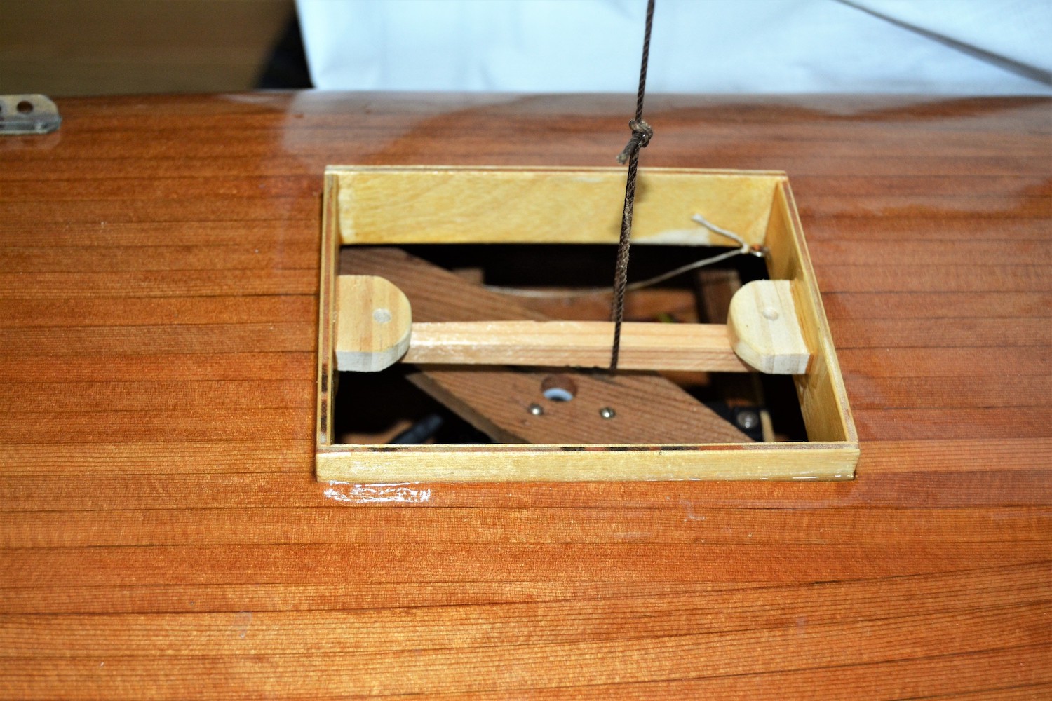
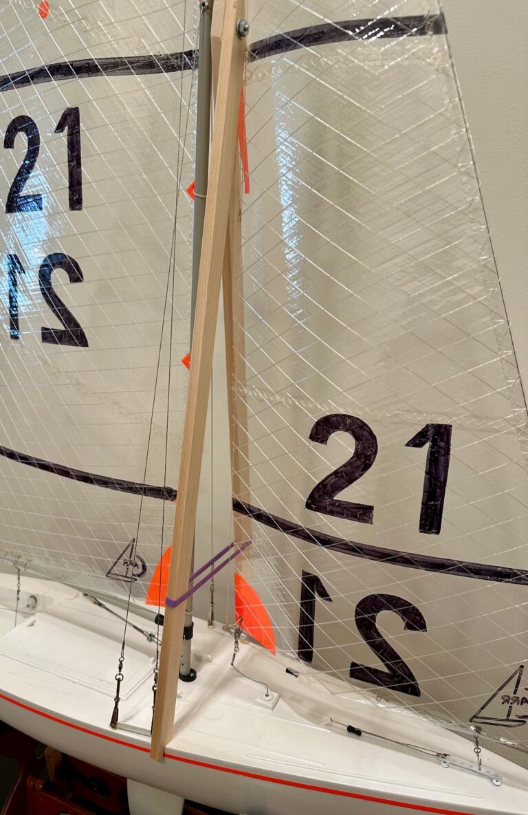
The photo shows a convenient method of suspending the hull. Note that the main hatch is almost always located approximately over the LCG and LCB because it is typically the widest and deepest part of the hull. I normally make my hatch frame strong enough to support the full weight of the boat so that I can use it as a carrying handle. For the photo, I inserted a temporary wooden bar fore-and-aft in the center of the hatch; a loop of string placed so that the boat hangs level reveals the LCG, which must match the LCB. An alternative is to insert a dowel across the hatch opening at the LCB (determined from the plans). Suspend the boat by this dowel. When the ballast is located properly, the boat will hang level.
I acknowledge that this method only determines the balance of the hull and ballast. We have not yet explicitly included the radio and rig. But the ballast is dominant, and the rest of the hull is likely the second-most weighty component, so we are very close. I would argue that the rig can be compensated by adjustment of the positions of the radio components, but the more fastidious among us could add small weights at the expected locations of the mast and radio to fine-tune the balance.
Float on your waterline.