Text and photos by John Stoudt
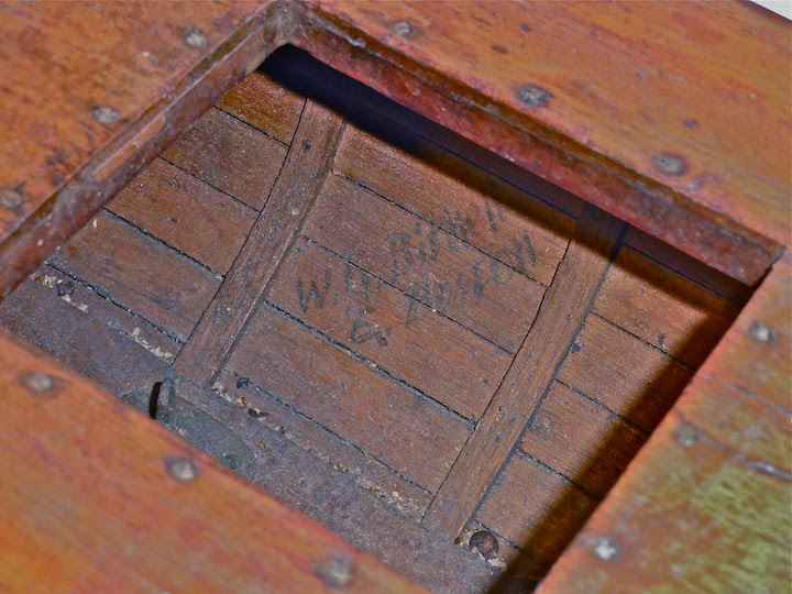
The owner of a vintage model yacht contacted me by phone and with subsequent texts and emails. He is a collector of nice, well maintained, older model yachts. He had this wonderful old A Boat and was upset about its condition. He wanted it to look nice again. He indicated to me when he acquired the boat he was told the boat was built by Bill Bithell. I asked him a few questions that made me question that claim. The most important factor is the fact that the “W. G. Bithell, E. Boston” signature (in pencil; see Fig 1) that you find in a Bithell boat was missing. I agreed to take on the project. It was delivered in the early winter, and the project began in earnest.
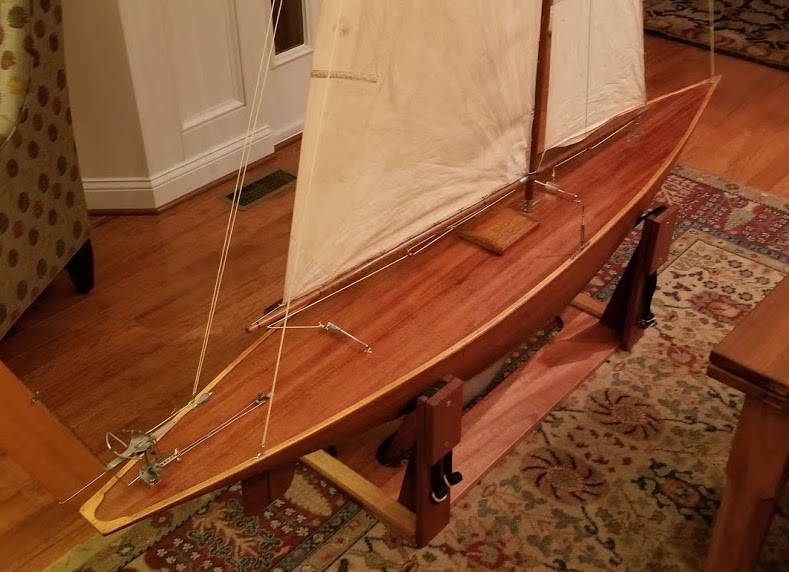
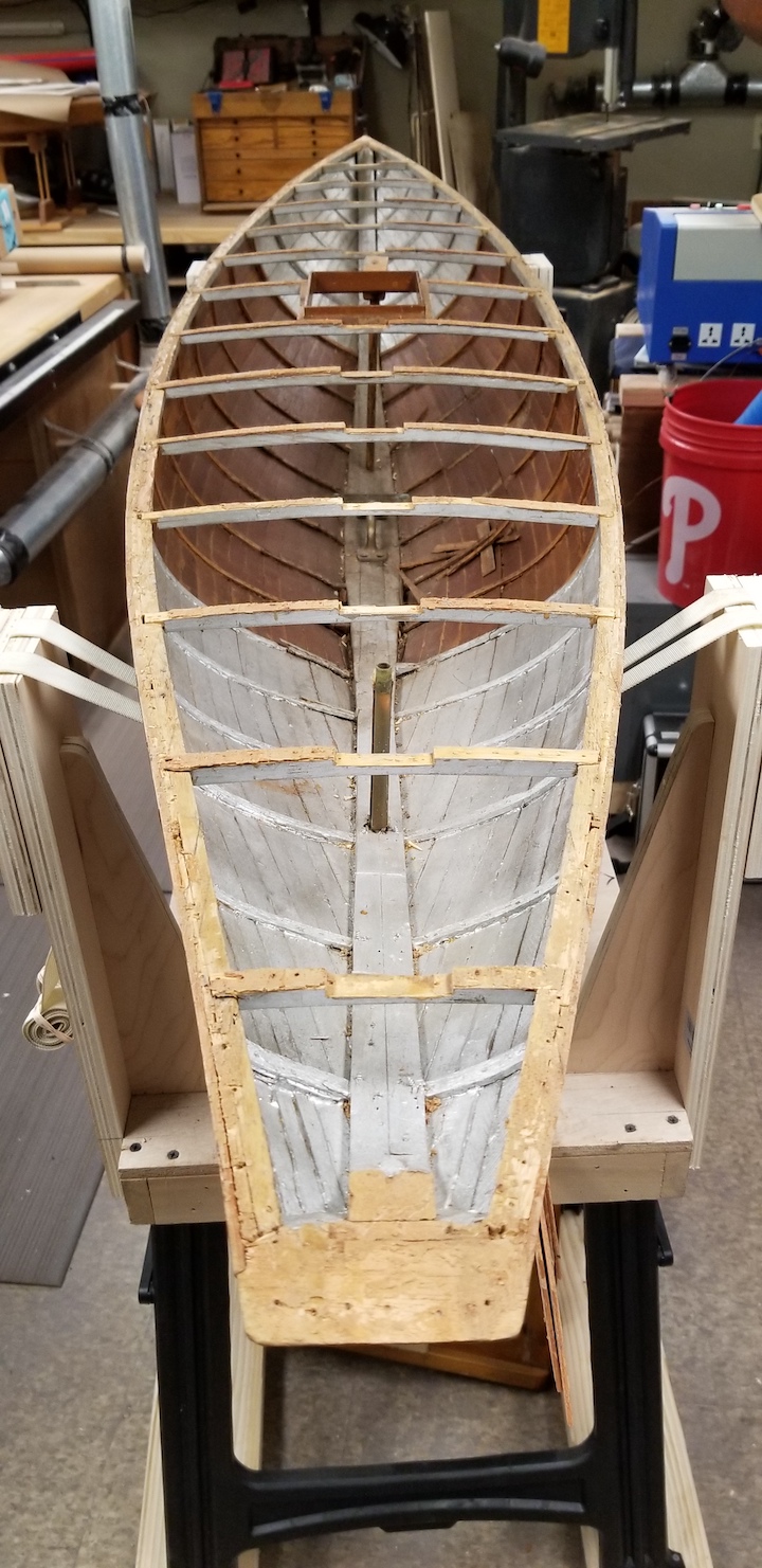
I must tell you that when the owner was removing the boat from his car, I almost told him to just leave it there. As he handled it, it was twisting end-to-end and side-to-side. He lugged it into my shop with great effort. This boat weighs over 60 lb. It got plunked on my one large workbench and seemed to occupy the entire shop. This was unacceptable because I have boats coming and going all the time. So I went to plan B. That was to build a simple mobile stand that could be moved around the shop. I intended it to support the boat on the ballast with straps placed fore and aft (18 inches in from the bow and stern). Once that was built and the boat was moved onto it, I felt a lot better.
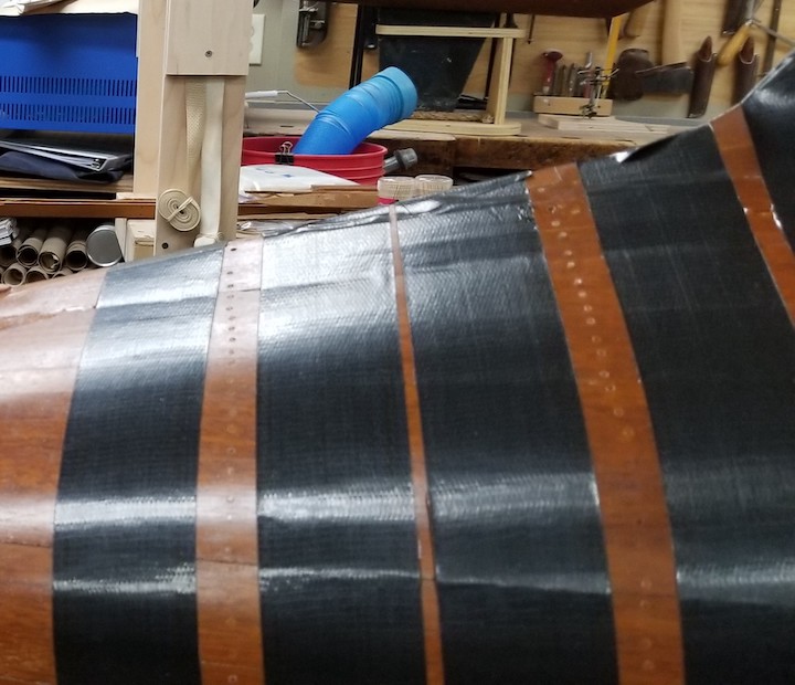
Note: Before I did any work on the boat, I stabilized the hull by placing it upside down and applying duct tape along the entire length of the hull.
Using an article written by Rod Carr and republished on our site (see Model Yacht Restoration Decision Making), I applied his criteria to the initial assessment of the boat. I placed this model yacht in Category III at a Level 3 Condition and documented the boat’s physical deficiencies and prepared a plan of work.
Observations (physical deficiencies)
This boat is planked with mahogany planks (hull and deck) approximately 3/32 by 3⁄4 in. The keelson and garboard pieces are also of 3⁄4-in mahogany glued together. The deck beams and the bent frames are oak. The toe rail, along with the bow and stern pieces, are made from maple (3/32 by 3⁄8 in) cut to fit the curve of the deck. The hatch cover is made entirely of mahogany with varied coloration. The spars are a straight, tight grain pine. All of the fittings are chrome-plated brass. The entire boat is glued with a synthetic resin adhesive. This hull was fastened entirely with toothpicks, and most of them were loose. The deck, hatch frame, and toe rail were also fastened with toothpicks.
- Many of the frames are compromised, broken and/or out of place.
- The planks have come apart, detached from the frames, or twisted.
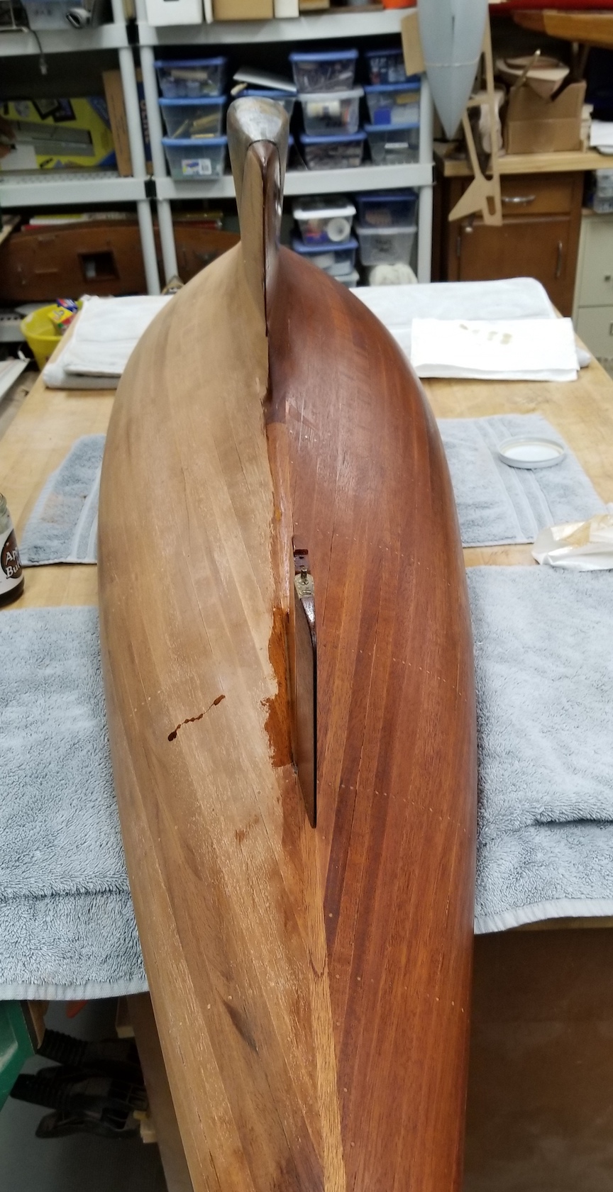
- The skeg is missing.
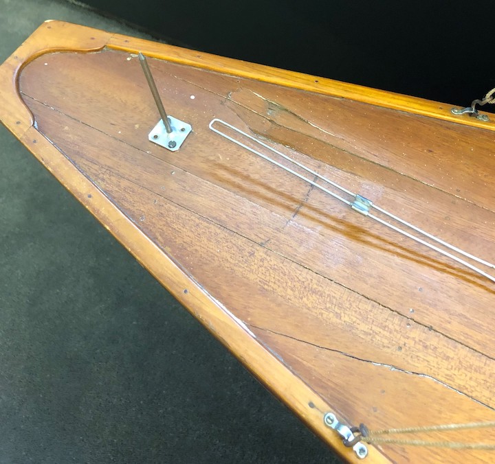
- The rudder is broken but intact. The rudder tube is loose, and the support is not glued in place. There is a pin alignment fitting at the bottom of the rudder, but the rudder shoe is missing.
- The deck is compromised with most joints having failed and one area “punctured”.
- The toe rail is in good condition.
- The hatch cover is finished poorly and some of the veneer inlays are missing.
- The deck beam glue joints have all failed.
- The ballast had been painted a mottled brass color and there is surface damage.
- Nearly all of the glue joints in the boat have failed.
- The vane steering pintle is on the boat, but the steering vane mechanism is missing.
- The rig was set up incorrectly with items installed that were just for show and had no function.
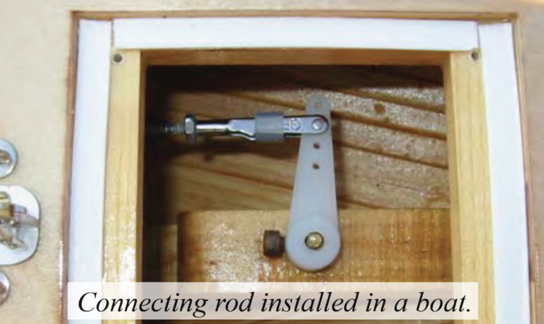
- The fittings are in very nice condition, and all of them are intact. They just need to be cleaned up. One turnbuckle is incomplete. There is a tensioning mechanism in the hull that allows one to apply tension to either or both shroud racks under the deck by simply turning one or both turnbuckles.
- There is a brass nose on the lead edge of the hull. It extended from bow to the ballast.
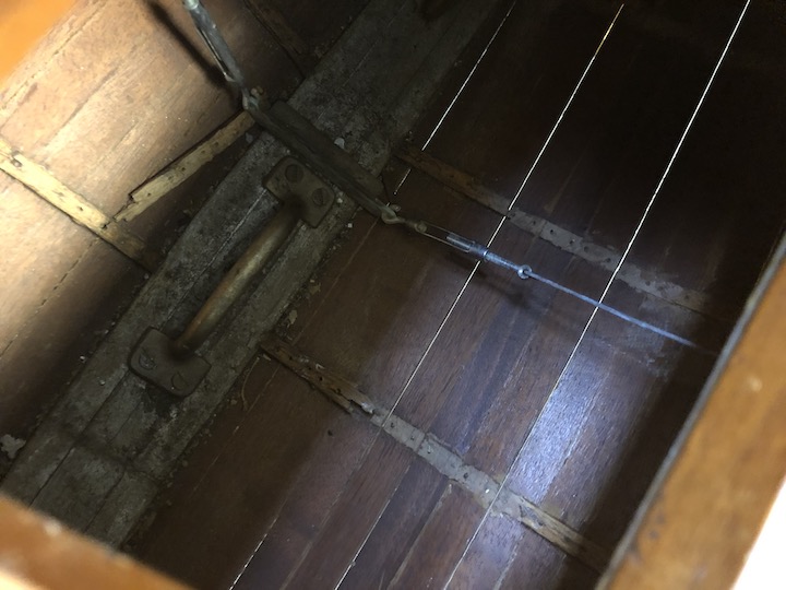
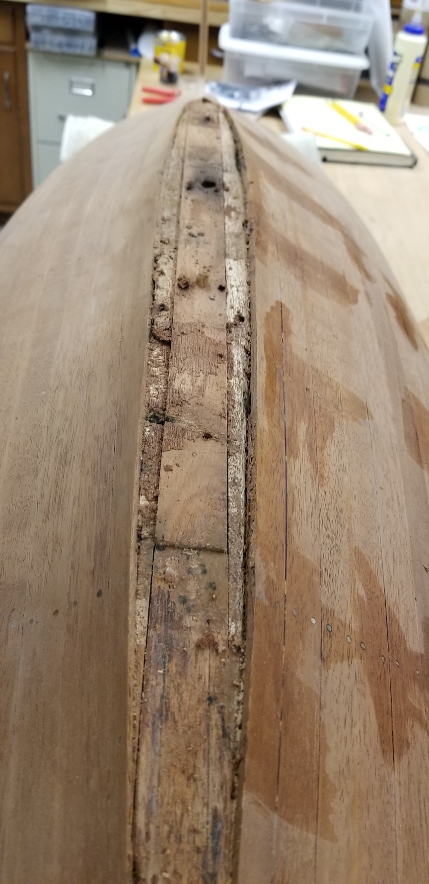
- Two thirds of the inside of the hull was painted silver – one third at the bow and one third at the stern. Interesting and probably later “repair”. See Fig. 5.
Plan of Work and Process
Dealing with the bad glue joints provide challenges and opportunities along the way. This plan was thought out ahead of time, but adjustments were made as work progressed and other options presented themselves.
Remove the deck
The only way the frames could be repaired was to remove the deck. This was done by carefully sliding a putty knife into the seam between the deck and the toe rail. Upward pressure was applied to lift the toe rail from the deck. As the pieces came off, they were labeled in pencil on the back for correct re-assembly. Next the putty knife was inserted between the top of the hull and the outermost deck plank. Upward pressure was applied and as soon as the plank could be grabbed by hand, additional pressure was applied as the putty knife was slid along the edge to release the plank. As the pressure was applied, the glue joints came apart, and the planks lifted away easily. The work had to be done around all of the toothpicks used as fasteners. Most of them were ultimately removed.
Restore and Augment the Damaged Frames
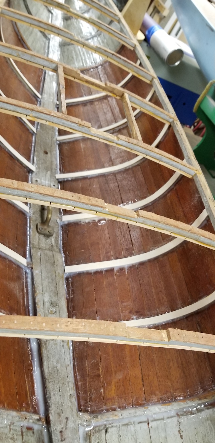
These frames were typical in many of these early boats. They were bent oak 1⁄8 by 3⁄8 in and were very dry and brittle. Their pieces (20 or so) were pulled out of the hull, sorted like puzzle pieces, and placed in the correct locations at each station. Only one 2-in piece was missing. This piece was remade and included in the restoration. The entire inside of the hull was cleaned and sanded lightly to provide a surface for the epoxy to adhere. Each piece was epoxied back in place. The pieces were held in place with clamps and props. An epoxy fillet was formed along each side of each frame. At the same time the planks were forced back into place with props. While this
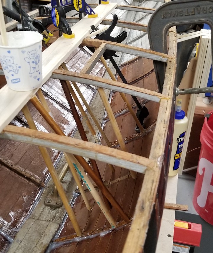
work was progressing, epoxy fillets were placed under the sheer strakes along the inside of the hull to reinforce the joint that I was unable to get apart. Roughly 40 frames were repaired or reinforced. The middle five frames on each side of the hull had plywood pieces sistered onto them to strengthen them. These frames were under the most stress from the over 50-lb ballast.
Hull Planking
Many of the twisted and misaligned planks went back into position with the uploading pressure applied by the mobile stand straps, countering the keel weight, and the props during the frame re-gluing procedure.
Skeg Construction
A piece of 3⁄8- by 4- by 7-in mahogany was used to make the skeg. There was a rabbet in the hull in front of the rudder shaft hole. This was cleaned out using a chisel, and the skeg was dry fitted into it. The skeg was cut and sanded into shape. It was then epoxied into the slot, and a small radius of epoxy formed between it and the hull.
Rudder Repairs
At the same time the rudder crack was repaired. The rudder shaft was removed from the rudder and cleaned up. The rudder was epoxied back together and sanded smooth when dry. Now that both the rudder and skeg were able to be installed in the boat temporally, the skeg and rudder were fitted with a brass rudder shoe.
Deck Repairs
As the deck was taken apart, as noted above, the planks were labeled with a “P” or “S” for port and starboard and with an “F” and “A” for fore and aft (in front of and behind the hatch opening). The planks were also numbered. So, you would see an S4 indicating the plank was the 4th plank from the starboard gunnel. At the time of deck plank removal, the hatch opening frame was also removed and labeled. The one joint that could not be gotten apart was that of the center deck plank and the king plank. This worked out fine because there was substantial re-gluing around this assembly as the deck was replaced and glued down. So even if this joint failed, the re-gluing would keep it together.
A hole had been punched into the deck near the pintle for the vane gear—no pieces fell out. As the deck planks were removed, I realized that I could repair the damage by gluing and clamping the compromised planks. As I flexed each damaged plank in the area where the damage was, I was able to get the pieces to realign. So, I flexed the plank, applied glue, and clamped the pieces together. They went back together so well I was able to sand out the unevenness. As I reassembled the deck and sanded out the irregularities it was evident, I could float clear epoxy into the small void that remained and finish right over it.
The Toe Rail
The toe rail came off in very nice pieces. It was all labeled and put aside. The nose pieces at the fore and aft end of the toe rail did break but glued back together very easily.
The Hatch Cover
I removed that last existing piece of veneer trim. After acquiring self-adhesive veneer, I cut and fit pieces into place. The whole hatch cover was sanded to fair in all the pieces and multiple coats of finish were applied.
Deck Beams
The deck beams and hatch opening beams were cleaned up, scraping off all the old glue and removing the loose toothpicks. The slots they fit into were also cleaned up. The beams were then glued back into place using TiteBond II. A couple of clamps were applied to the exterior of the boat to pull the beam back into its original dimensions against the ends of the beams.
The deck beams flexed and had too small of a cross-sectional area, especially at the king plank notch. Sisters were made of 3/16- by 3⁄8-incedar with band saw kerfs placed every 1⁄2 in. These were then glued to the beams. The kerfs were made to reduce the amount of flattening of the deck beams when the sisters were glued in place. The ample amount of glue that was applied to the joint flowed into the kerfs and strengthened the assembly.
The Ballast
The finish was removed from the ballast. I found some areas of the ballast where the lead had not flowed completely into the mold when it was cast. These were filled and sanded smooth in readiness for finishing.
Glue Joints
The glue used on this boat failed over time. Whether this boat was built in the early 1930s (as noted by the seller) or the mid-1940s which align with the time when Bill Bithell was building these boats, it is an old boat, and the glue just failed. The glue was probably a formaldehyde resin-based adhesive.
The Vane Steering Gear
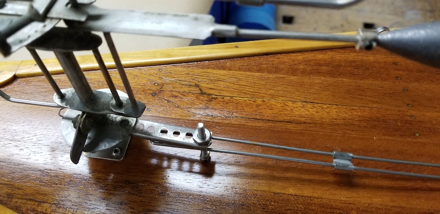
The vane gear was missing; however, the pintle was in place. A vane was acquired from a friend, cleaned up and installed on the boat. Slight modifications were made to enable this vane to engage the rudder control arm.
The Rig
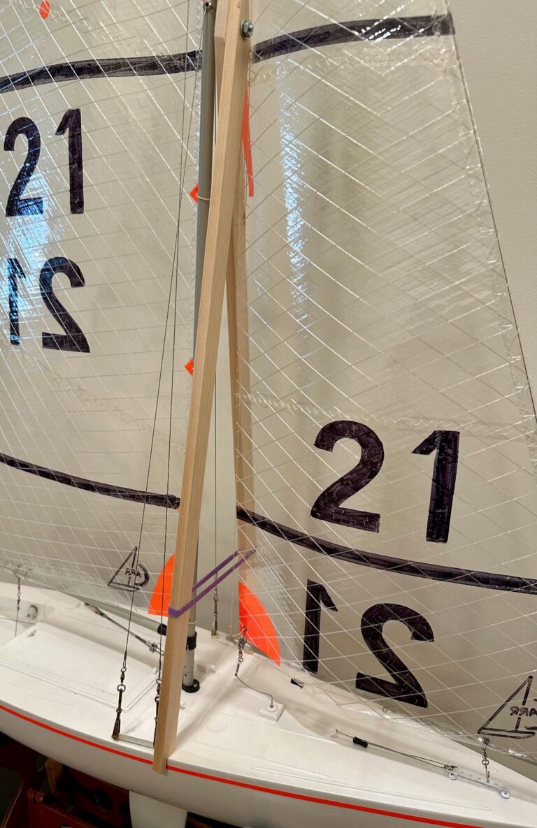
The rig was in very nice shape. There were a couple of tears in the sails, which have been repaired. After consulting with Rod Carr and the owner, it was decided not to replace these fine old Egyptian, William G. Bithell (WGB) sails with new sails.
The Fittings
This became a Murphy’s Law issue. The turnbuckle vibrated loose, and the body of the turnbuckle fell into a nook in the car while it was being transported. The part eventually turned up. Remember to tape these turnbuckles to keep them from vibrating apart when you travel with a boat like this.
An “Oh No” Moment
While I was rolling the boat from one side to the other, I was holding it by the keel (ballast), the heavy end of the boat. Next thing I knew the whole keel had separated from the keelson. Yikes, now what do I do? I do what I had been contemplating all along; remove the ballast from the boat (now a smaller piece of attached keelson). This involved removing two exceptionally large wood screws and the attachment bolt. When this was done, I was able to clean up the keel and repair it. It is not unusual on a casting this large to have cavities form while the lead is cooling – shrinking. If you do not have large feeder sprues to keep the molten metal feeding into the casting, the large mass of metal shrinks too quickly, thus the cavities.
Fairing in the Planking
The deck and hull planking went back together nicely, but they were still irregular and did not line up completely. So some sanding was necessary. I sanded the deck prior to reinstalling the hatch cowling and toe rail. I used a random orbit sander with a 150-grit sanding disk. I then went to 220-grit paper. This is tricky because you must keep the sander moving rapidly to avoid sanding holes in the surface. The hull was a different story. It needed more work with both the random orbit sander and sanding (fairing) board.
Finishing
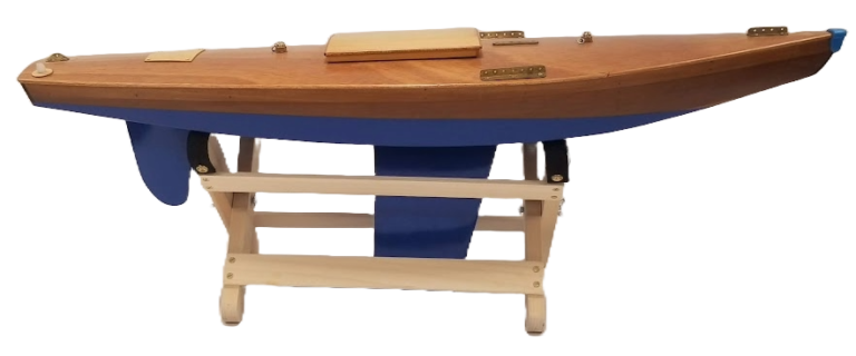
I decided to finish the boat using WaterLox. This finish provides a wonderful, amber hew and is totally waterproof and durable. The first area I worked on was the deck applying 12 coats of finish first by brush and then by wiping. Sanding or steelwooling was done between all the coats of finish. The last coat was applied with a rag and rubbed out vigorously to develop a matt finish. I allowed the finish to dry for a couple of days.
I flipped the boat and applied finish to the hull. A similar process was used to develop a nice finish on the hull, applying multiple coats of finish with sanding and cleaning between coats.
The ballast had been painted and not finished naturally. As I work to clean up the ballast, I discovered that there were voids that needed to be filled necessitating the need to repaint the ballast. I used acrylic paints to paint the ballast to look like aged lead as the ballast was lead.
The Bill Bithell Argument
The seller of this boat sold it as a William G. Bithell (WGB) boat and dated it as early 1930s. There is one thing WGB did when he built a boat: he signed it in pencil in the bilge. There is no evidence of the signature in the usual location or anywhere inside the hull. Evidence suggests that this boat had been worked on at least once, probably more than that, before. Therefore, there are four possible scenarios:
- Maybe WGB forgot to sign this boat.
- Maybe this boat was built before he started signing his work (the rig notations do not support this).
- The signature was inadvertently removed during a prior restoration.
- It is not a Bithell built boat.
The rig is, without a doubt, a WGB rig for the following reasons:
- The sails are made from high thread count Egyptian cotton which WGB always used.
- The sails have the Wm G Bithell labels on their lead edges.
- The main sail is fixed-footed, a characteristic of WGB sails.
- The fittings are chrome plated, which is very typical of WGB fittings.
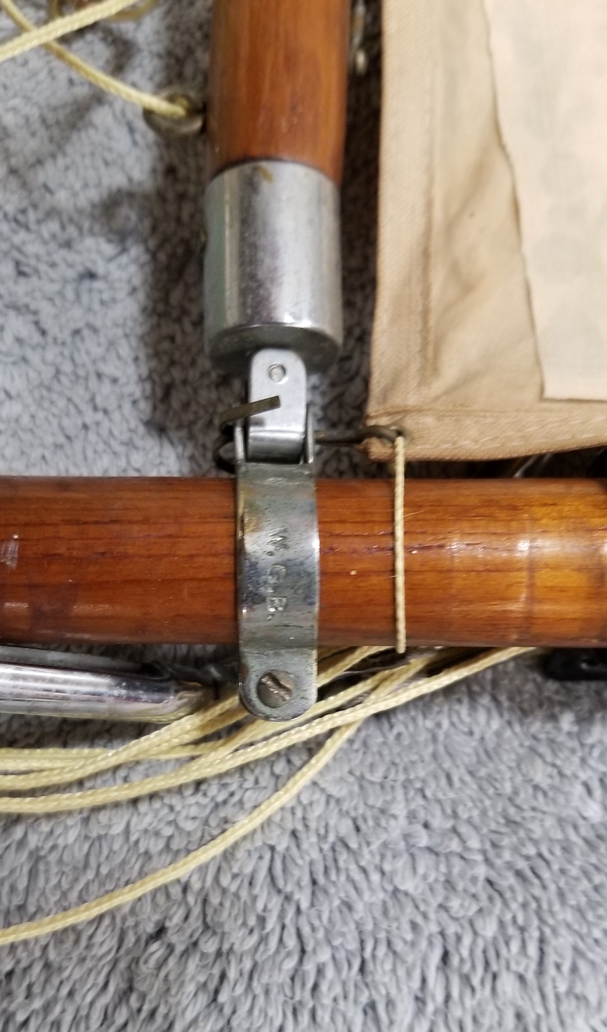
- One fitting has the WGB stamp on it.
- The lines are not original, and the rig is incorrectly done and not identifiable as WGB work.
Note: I have an M Class WGB rig including sails, and the similarities are striking. I would say they are made by the same person.
Dating the Boat
This boat was thought to have been built in the early 1930s. If this is a WGB boat we must remember he graduated from MIT in 1932. His national championship A boats were 1935, 1936, and 1937. When did WGB start to make fittings for sale (quite an extensive assortment) and when did the plating of his fittings begin? Did he have time to do this in the mid to late 1930s when he was competing on an international level? So, the question is when was this boat built? I invited Mike Denest, the former AMYA International A Boat class secretary, to take a look. He came to the house to see the boat in person. His estimate, based on the size and shape of the boat, places it in the mid to late 1940s. There was a hiatus during World War II in building and racing which further suggests this boat’s origin is better placed in the mid to late 1940s.