Article and Photographs by Gudmund Thompson
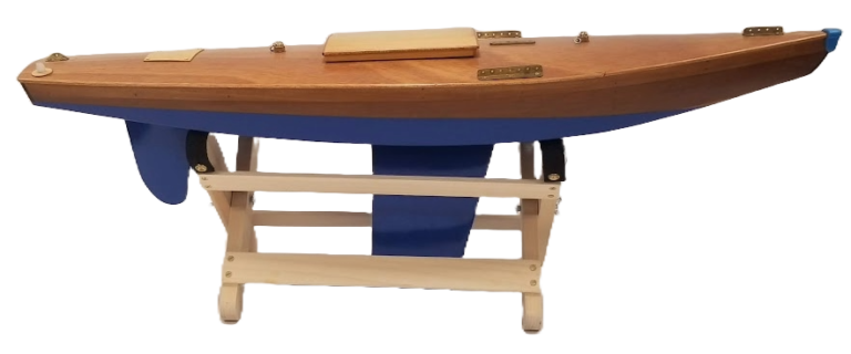
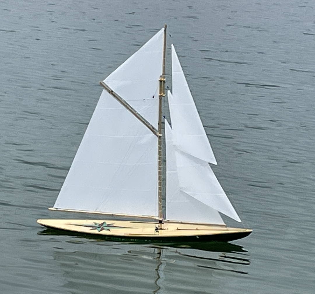
My winter project this past year started with Alan Horne’s beautiful Nottingham 60 hull, and, as I want the boat to be a test bed for a number of sail rigs, included the installation of running backstays.
Here is what I have done in the process of setting up the runners.
Throw Calculation
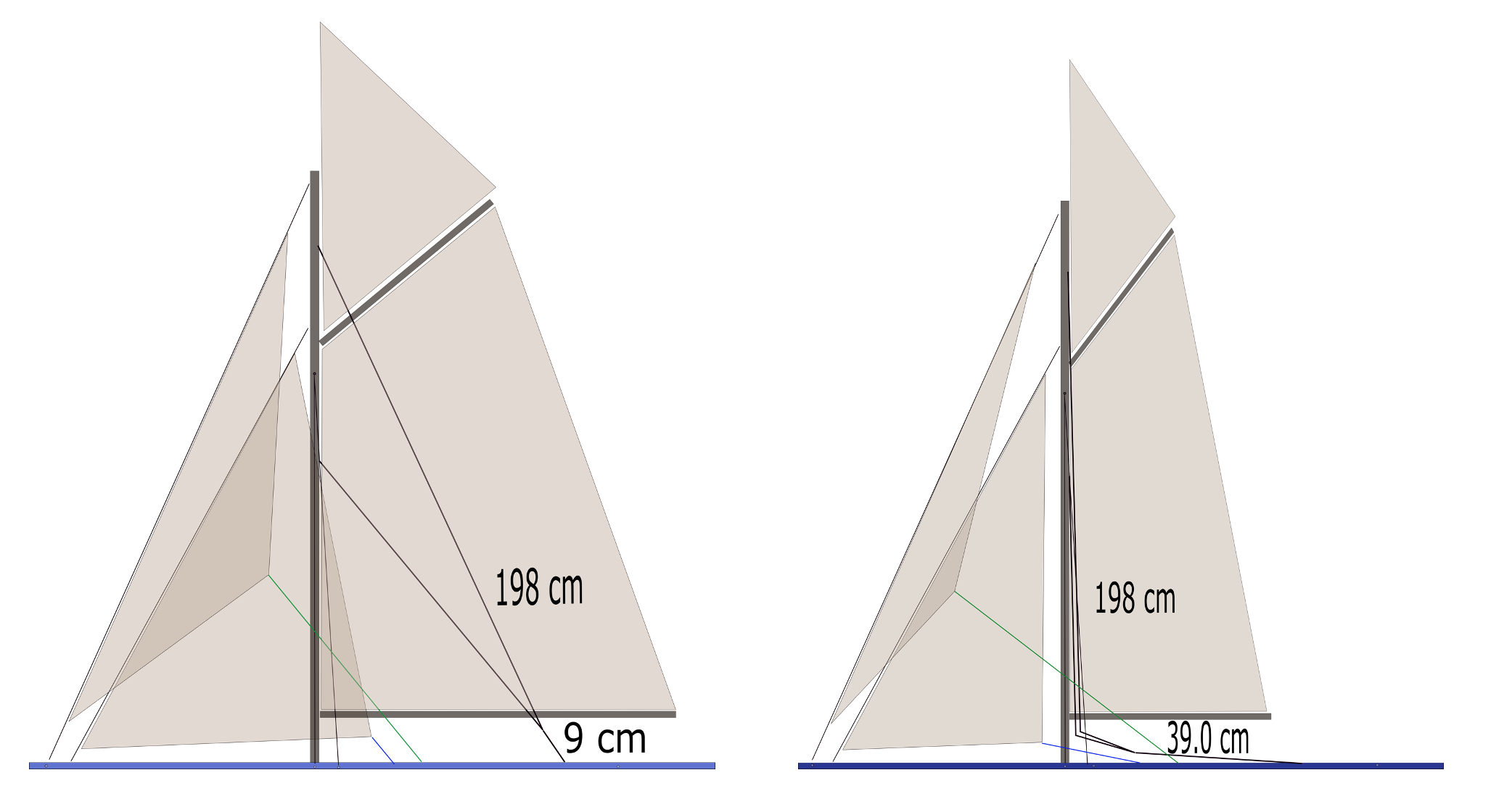
Because one of the rigs I wanted to mount will have numerous headsails and gaff mainsail, I sketched the setup in INKSCAPE (a free CAD program) using the dimensions of the hull and my projected dimensions of a reasonably balanced set of sails. This allowed me to calculate (among other things) the amount of line throw that would be required to make running backstays operational. That number, as shown in the sketch, was 30 cm (about 12 in).
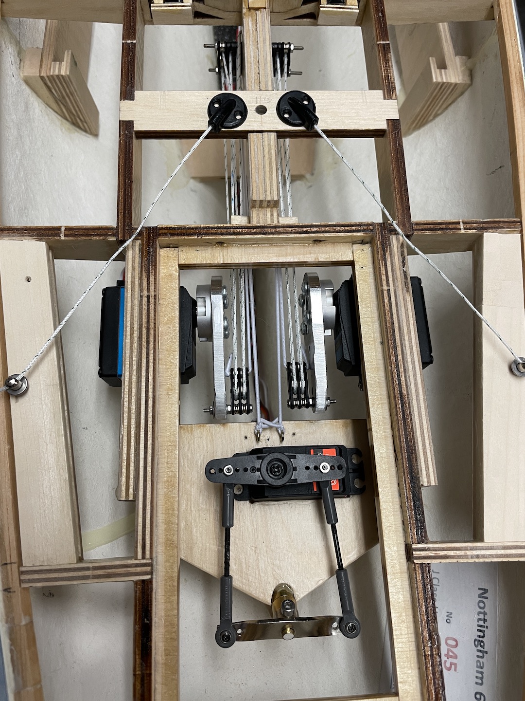
Next, I considered the servos that I wanted to use and chose a location in the hull that allowed access to them and their lines. This required a little modification to Alan’s building instructions, but by moving the rudder servo back and down a bit, I was able to get the 35 kg-cm servos that I had on hand mounted directly below the aft hatch. My assumption was that the success of the runners would depend on them being securely incorporated into the deck substructure – not on the size of the servo itself.
The next calculation was the size of the servo arm that could be used in this location. This turned out to be about 4.5 cm—any longer and the end of the arm touched the rudder servo tray as it was rotating into the overlock position.
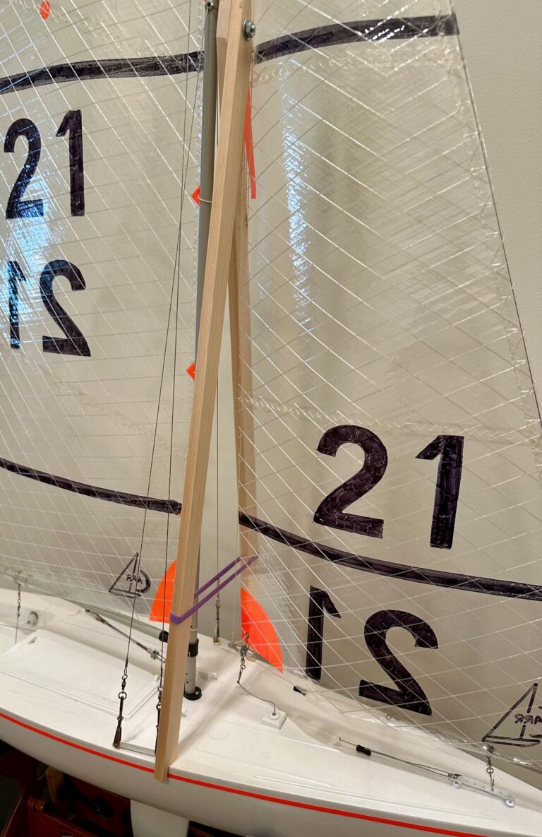
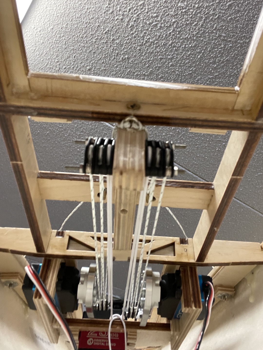
Finally, in order to get the required 30 cm of throw, I determined that the servo arms would need to be augmented by a 4:1 block and tackle system. This was accomplished by mounting a rotating two-sheave block to the servo arm and a three-sheave block to a beefed-up deck support that runs between the two hatches. (This setup also includes an elastic line to maintain the correct orientation of the blocks during the movement of the servo arms.)
Programming
My normal programming scheme for a yacht with an overlapping foresail (controlled by separate port and starboard sheet servos), is to use a pair of modes (which are simply a clever way of managing mixes in my high-end computer radio) to deal with the port and starboard points of sail. I did the same thing with the Nottingham 60.
It is worth noting, however, that while my high-end radio is a lot of fun to work with and provides an astounding level of flexibility and some really cool telemetry, it is not really necessary. A regular, eight-channel, digital transmitter capable of managing a large number of mixes would work fine. Indeed the new, quite inexpensive, transmitters that are based on the Open TX software will do the same thing as my fancy radio, at a fraction of the cost.
Starboard Tack Mode
In this mode, with the apparent wind coming over the right side of the boat and the main boom and foresail(s) swung out to the left, the running backstay on the right side of the boat will be in the overlock tensioned position while the runner on the left will be completely un-tensioned and will pay in and out with the movement of the main boom. (Any tension in this runner will at best cause a crease in the mainsail and at worst, interfere with its movement.)
Port Tack Mode
Here, the opposite is the case. The left-hand runner will be in the overlock tensioned position while the right will be un-tensioned.
Overlock—Needed?
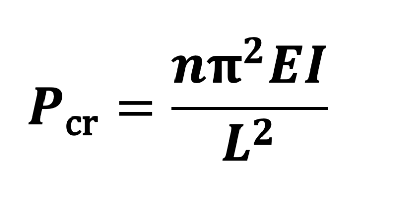
If anyone has wondered why the servos need to be in the overlocked position when they are being called upon to support the mast, let me quickly run some numbers. The servos are rated at 35 kg-cm, but with the servo arms being 4.5 cm long, the actual output at the end of the servo arm is only 7.78 kg. This 7.78 kg when it comes out of the 4:1 block and tackle, drops to 1.95 kg, or about 4.3 pounds of tension when the servo is rotating, and this assumes zero loss to friction. If, however, the servo arm has moved into the overlock position before the mast needs the full support of the runner, the required tension can be provided by the static positioning of the idling servo in the deck’s superstructure.
Sailing
While my computer-based transmitter has many subroutines engaged at any given time, only four inputs are needed to manage the yacht. The “throttle stick” controls not only the main sheet, but also the port and starboard foresheets and the running backstays through all points of sail. A two-position switch selects the port and starboard tack modes, the “elevator stick” facilitates a safe gybing maneuver, and the “aileron” stick controls the rudder.
Close hauled tacking from port to starboard is achieved by using the rudder to maneuver the boat through the wind and flipping the port-starboard switch to change modes. If this is done correctly, and without moving the throttle stick, the starboard foresail sheets slacken while the port-side sheets tighten, the wind pushes the main boom across the boat, and the port-side runner loosens while the starboard-side runner tightens. If all this happens, the boat falls off onto roughly the same point of sail, but on the opposite tack.
Unfortunately, while the process above may be appropriate for going from close hauled to close hauled, I am seriously concerned about gybing. Here, it could be possible for the tensioned runner to be released before the needs-to-be tensioned runner is firmly in the overlock tensioned position. The consequence could be a stalled servo (using lots of electricity) and a poorly supported mast—probably not an ideal situation.
My solution has been to program my radio such that gybing includes a moment when the main boom is being tightly held at the center-of-boat position by the mainsail sheet. By doing this, the mainsheet will support the mast while the runners swap overlock position—the boom needs to pass through this position during any gybing maneuver anyway, so this is just a matter of timing.
The gybing process only uses the rudder and elevator stick (not the throttle stick). The former turns the boat out of the wind, while the latter pulls the main boom to the center of the boat and tightens both runners–a sensor on the mainsail’s closed loop line signals when this has been achieved. Then, with the boat passing through the wind, the port-starboard switch is flipped and the elevator stick is eased back to the center position. When done correctly, as when tacking, the boat falls off onto roughly the same point of sail, but on the opposite tack, and the gybe is very smooth with little drama. I should point out that in moderate to heavy winds, the process depends greatly on the very powerful Australian mainsail servo that I am using.
This has been a very interesting project, and my hopes have been greatly surpassed. The boat both sails and maneuvers extremely well, and I have never worried about the running backstays or their ability to do their job.