by H.M. Savage and J. Case (1906)
Model yachting, like all other sports and pastimes, has been infused with the spirit of the age. Both in the building and sailing of model yachts, skill and science have raised this pastime from what formerly used to be considered as one most suitable for juveniles to what is now acknowledged to be one of the most clever branches of model-making, requiring to be followed with success, a certain knowledge of nautical matters, some acquaintance with mechanics, the laws of motion, opposing forces — as wind and water resistance, which play an important part in yacht designing — some idea of marine work, and a considerable amount of patience and technical skill. Of course, it is clear that the man who simply goes into a shop or gives an order to a professional builder, pays his money, and goes out with the model under his arm, belongs to quite a different category of enthusiasts to those who build their own models, and follow the sport with a thoroughness that almost elevates it to a science.
The coming into existence of The Model Engineer — the recognized official organ of the model yachting fraternity — and the sympathy which its Editor has always extended through its columns to any who are minded to contribute articles of general interest or merit, have done much to elevate the tone of the sport; and it is certain that if it were not for The Model Engineer the most valuable series of articles which have ever been written on the subject — those of the late Mr. Wilson Theobald — would never have seen the light of day. It is much to be regretted, in the interests of the sport, that the early death of this clever and gifted contributor has deprived the readers of this Journal of the advantage of his technical skill and thorough knowledge of model construction and designing.
The season of 1905 has been remarkable in one feature, namely, the tendency to increase the displacement and measurements of models now being sailed, and to build them more and more on the lines of their large sisters. Thus we see that there are many models now being sailed having load waterlines of 3, 4, and 5 ft; whilst some have made their appearance this season with load waterlines of 5 and 6 ft, having displacements exceeding 200 lb, and carrying from 4000 to 8000 in2. of canvas. These latter are, of course, powerful sea-going models; and it is with this class that this article proposes to deal.
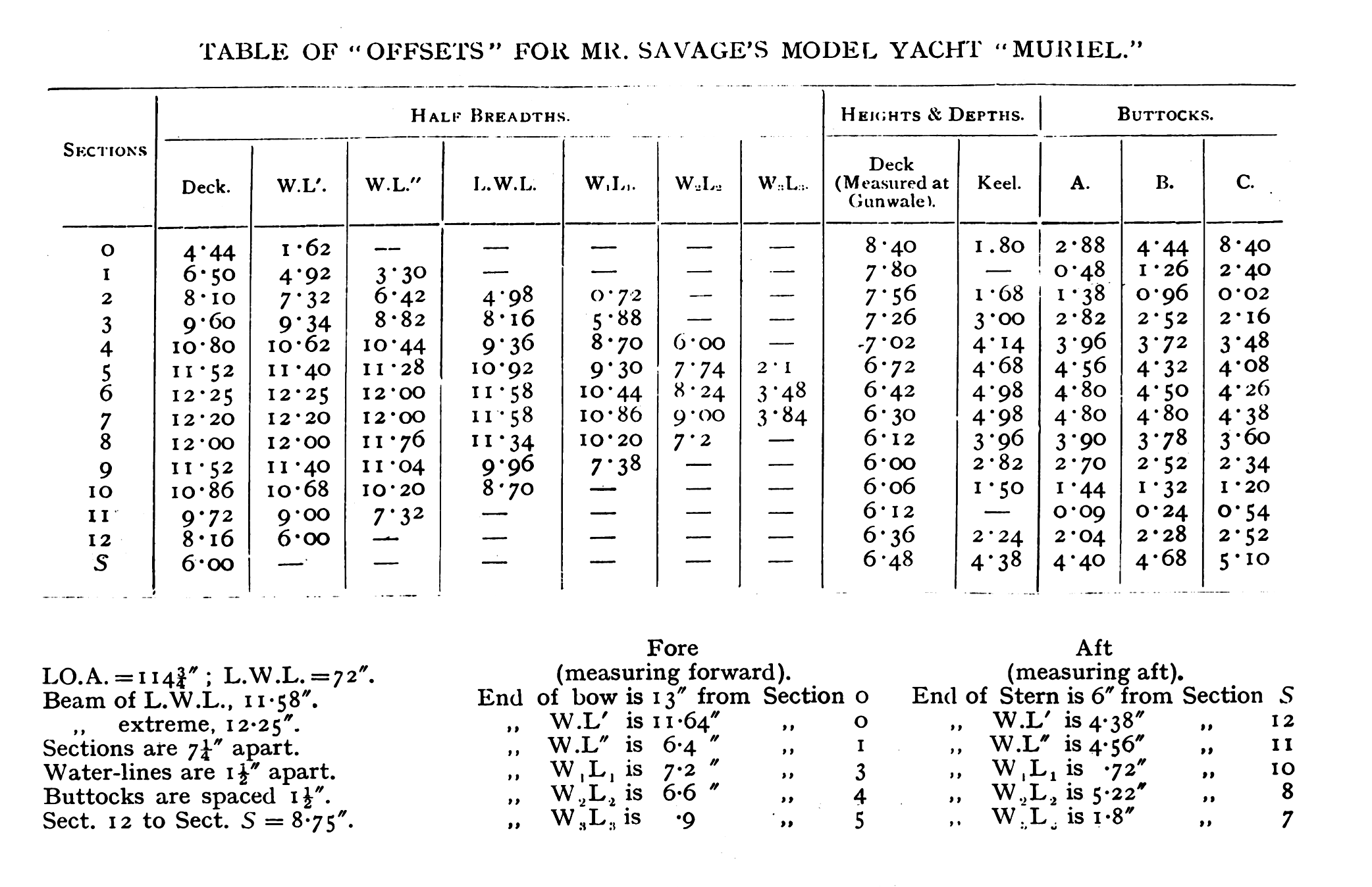
Model Yacht Muriel (Overall Length 120 inches, Sail Area 8,784 square inches) Designed by the Late W. H. Wilson Theobaud, M.A., Built by Mr. H. M. Savage.
Visitors to last year’s Conversazione [The Society of Model Engineers adopted this scholarly term for their annual conference. — Ed] of the Society of Model Engineers, at the Holborn Town Hall, no doubt remember the large model cutter yacht Muriel exhibited by one of the writers of this article, who was also its builder. The model had just been completed, but had not been sailed, so that its sailing capabilities were still unknown factors. During this summer the model was sailed in all kinds of wind and weather in Weymouth Bay, and as her performances exceeded the anticipations of her builder, it is proposed to enter fully into the details of her construction, in the hope that some other readers of The Model Engineer may be tempted to try their hands at a similar craft, with a view to comparing results. We should like to invite skilled model builders, such as Mr. Bishop, of Bristol, and some of his friends in that district, to try their hands at such a model, and if others could be found to follow suit, a new impetus would be given to this sport, and it would be most interesting to follow the results of their labors. Of course, the building of a model 10 ft long is a piece of work which requires some courage to undertake, and as there were no plans or designs to aid the builder of the Muriel, he discussed the proposal with the late Mr. Wilson Theobald, who entered at once into the idea with that thoroughness and zeal which was characteristic of everything he undertook. Mr. Theobald first suggested the building of a craft even 12 ft long, to carry no less than 13,000 in2 of canvas, and to have an estimated displacement of about 250 to 275 lb The writer, however, found that his workshop would not allow of such dimensions to be followed, so it was decided to reduce the over-all length of the craft to 10 ft, with a proportionate reduction of the displacement to about 230 lb and, previous to commencing on the plans, Mr. Theobald inspected several of the smallest yachts afloat to guide him in the choice of his designs. The results of his investigations are shown in the drawings and plans given herewith; but as this design was purposely not followed in all particulars by the builder, for reasons which will be given hereafter, the modifications introduced by the latter will also be described, so that anyone proposing to build such a craft may have alternative plans to work from.
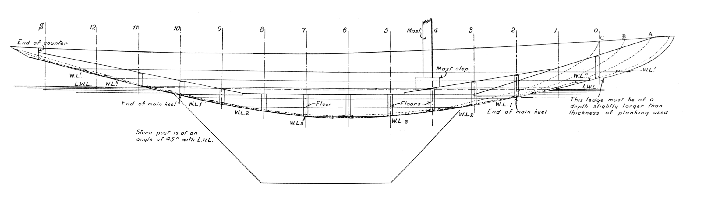
The main points on which the builder and Mr. Theobald held different opinions were the adoption of a light inside keel, to be strengthened by floors (as shown in his plan) and two very thin decks of 3/16-in wood each, to be covered with canvas and painted white. The builder’s objections to these items were: Firstly, that, seeing the enormous weight of lead ballast that would have to be carried in the bulbs on the fin, extra provision would have to be made to support such a weight from the inside, as the leverage on the fin when the model is sailing at a heavy inclination would most likely strain some portion of her internal structure; secondly, the building in of “floors” would have proved a very tedious and tiresome job; thirdly, two thin decks of 3/16-in wood would never stand the upward tension exerted by the cleats and screw eyelets necessary for the shrouds, stays, and running tackle; fourthly, such a deck would certainly have warped with the exposure to water; and fifthly, a painted canvas deck would have always looked dirty, and spoilt the general appearance of the yacht.
The following modifications were therefore made in the drawings and carried out in the construction:
- Instead of a keel, as shown, 1 in broad and 3 in deep at the midship section, one was substituted 2 in broad and 4 in deep at the midship section of solid oak, scarped at the stem portion, as per plan, thus dispensing with the floors entirely. The wisdom of this was proved eventually, as, in order to fix the fin clips to the under water body, four bolts (1/2 in diameter) had to be put through to the inside, and this would have been rather risky with a keel only 1 in broad.
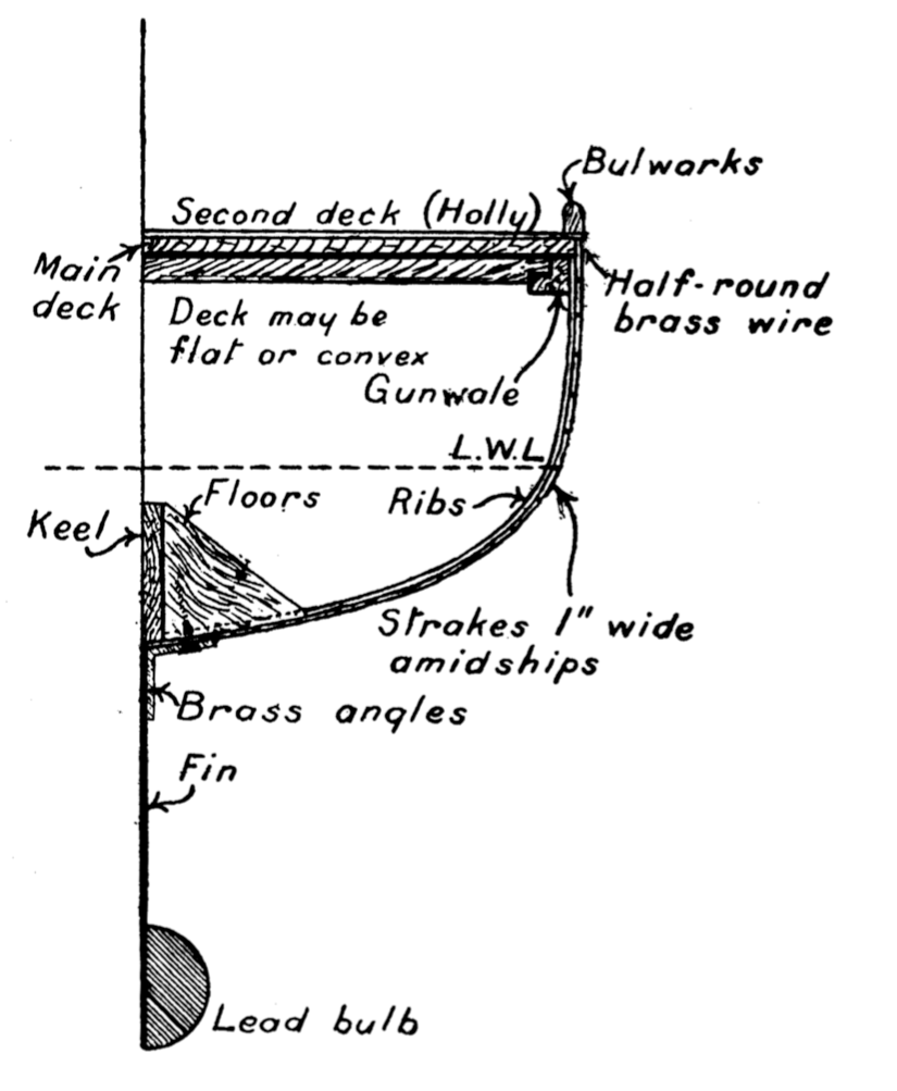
- The freeboard was increased 3/4 in by putting on, firstly, a solid deck of American whitewood 1/2 in thick, which was again overlaid with a second deck 3/16 in thick, of white holly, thus making a very strong tie to the gunwales, stem and stern pieces, and considerably stiffening the whole craft.
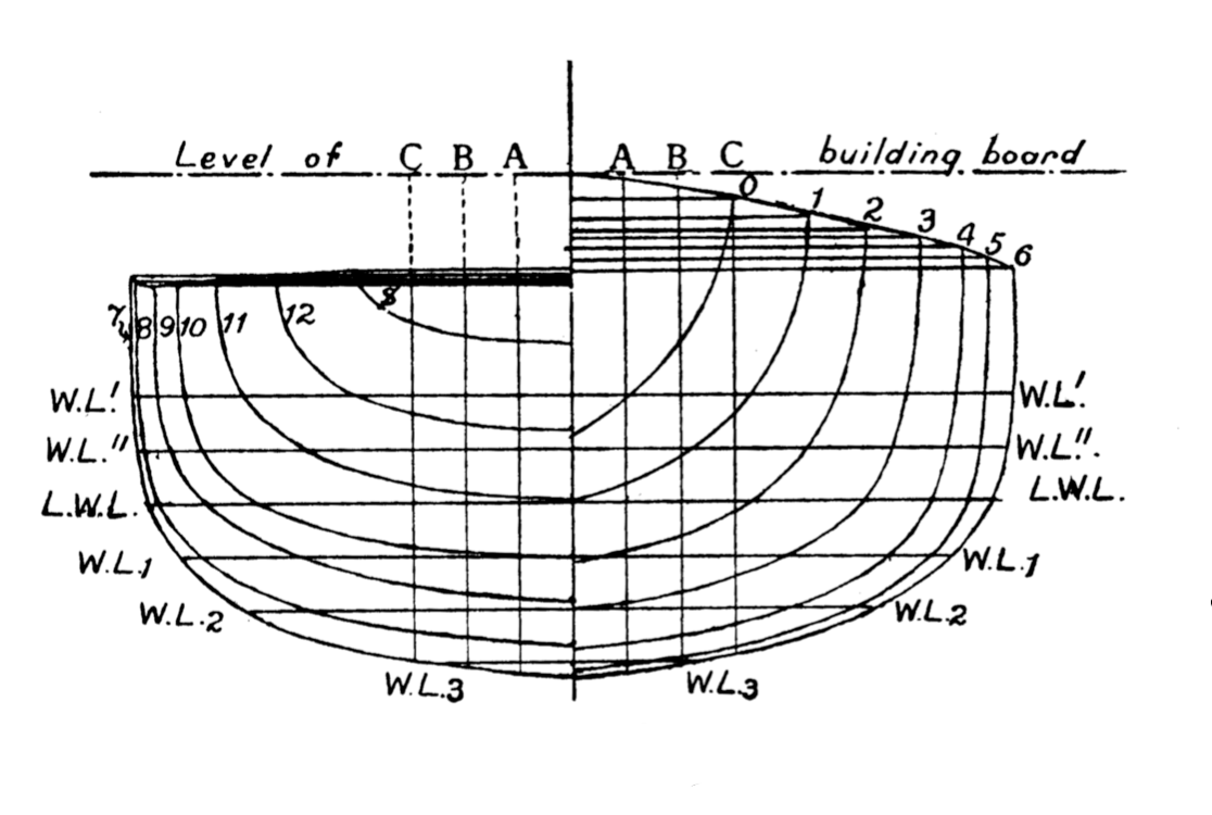
- The suggested building frames, as shown on plans, were discarded entirely, as it would have been very difficult to make them and attach them firmly to the building board. Instead, therefore, the ordinary temporary solid frames were used, cut out of 1/2-in boarding, and these proved amply sufficient for all purposes.
The net result of departing from the plans of Mr. Theobald was an increase of the total displacement of the yacht by 33 lb, bringing it up to 233 lbs; on the other hand, it made her very much more powerful, although perhaps slower in point of speed. This was considered advisable, seeing that she was destined to be sailed in all weathers and in rough water.
Sail Plan
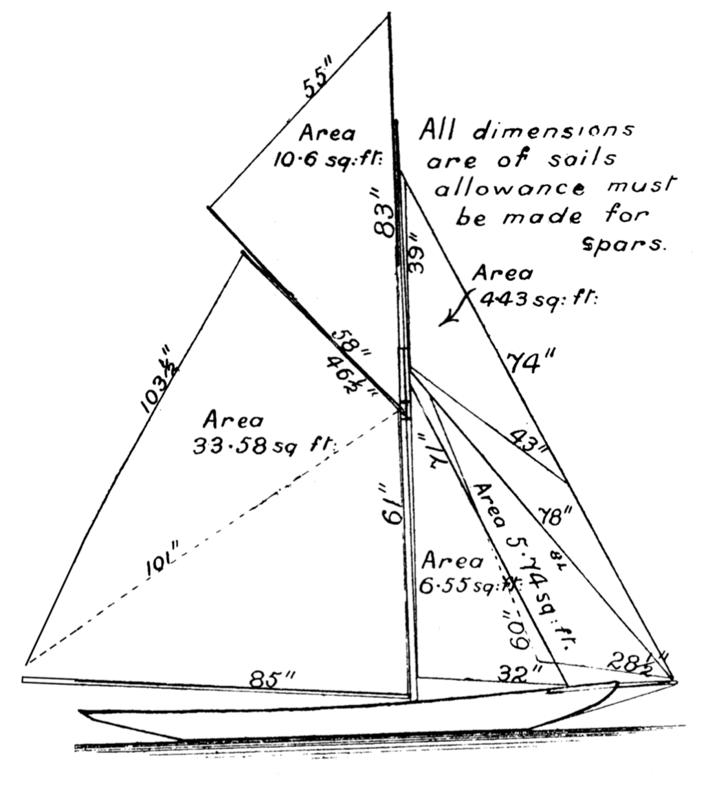
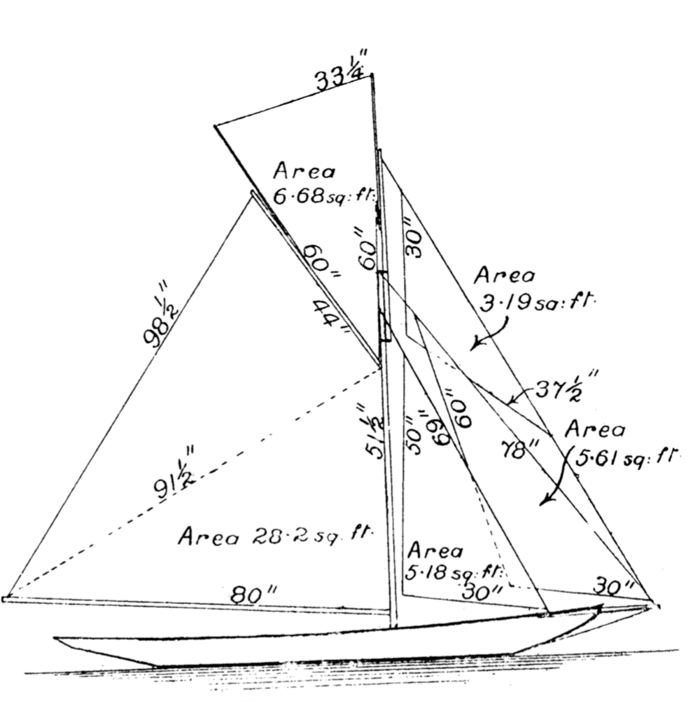
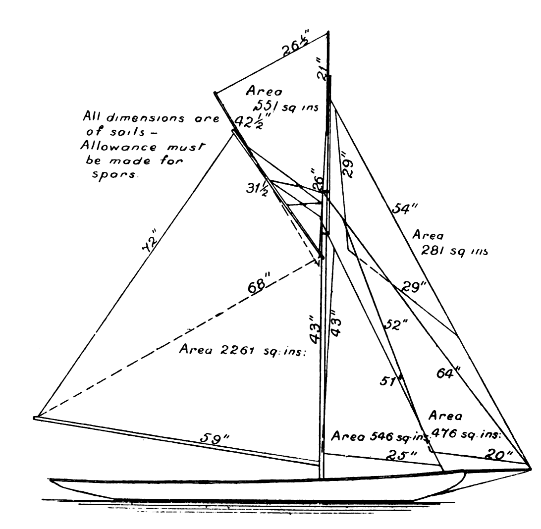
Two sail plans are shown, Fig. 6 being the one originally designed, and enables shorter spars and masts to be used. It seemed, however, to have the appearance of being top-heavy, and consequently the plan (Fig. 5) was designed by the builder and substituted as being more graceful, and less liable to cause excessive inclination. It entailed, certainly, the use of longer and heavier spars, and as there proved to be a good margin of stability, there was no disadvantage. Even when sailing in the strongest winds with all sails set, including the large jackyard [A “jackyard” is an extension to the gaff of a gaff topsail. — Ed] topsail, she went through the water with scarcely the bulwarks awash, and stood up grandly to all her canvas.
Her actual sail area worked out as follows:
Mainsail: 33.58 ft2
Jib: 5.74 ft2
Jib topsail: 4.43 ft2
Foresail: 6.55 ft2
Topsail: 10.70 ft2
Total: 61 ft2, or 8,784 in2 of canvas.
Construction
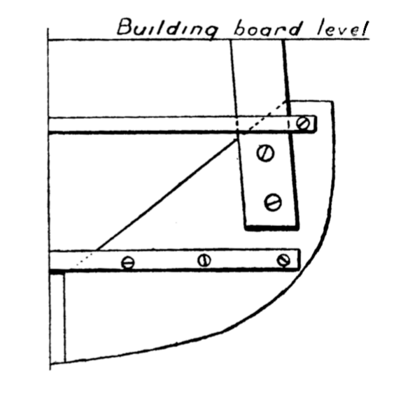
The usual method of construction was followed, the boat being built upside down on a building board, each temporary mould being secured to it from underneath; and in order to secure the keel firmly in the mould slots, and brace the whole to the building board, holes were made transversely through the keel fore and aft, and through these, strong galvanised wires were passed, the ends of the wires being again passed through holes in the building board, and twisted together underneath under strong tension. The usual longitudinal battens were used to fair the moulds; the timbers were steamed in a similar apparatus to that described in the article in The Model Engineer of April, 1903, for the building of the Hilda, and, after having been steamed, were passed, whilst hot, from gunwale to gunwale, except a few at the bow, which were divided at the keel, and held in position to temporary strakes 1/2 in wide by ordinary clothes pegs—a simple, cheap, and effectual method, which can be thoroughly recommended. The permanent strakes (mahogany), 1 in wide amidships, were fixed throughout to the timbers by brass screws, some 15 gross being used in the strakes alone, the screws being 3/8 in long (No. 2). All heads were countersunk, which was only possible by using one of the ratchet screwdrivers with countersink attachment and the screws were driven home by simple pressure of the same tool, no turning movement of the wrist being necessary.
The fin is made from sheet zinc, No. 12 S.W.G., and is detachable, being held between the brass clips by brass bolts and nuts. The brass clips were cast from the builder’s patterns, and, as already mentioned, are fixed to the keel by long 1/2-in bolts, passing through to the inside, and fixed with hexagon nuts. To complete the appearance of the model, a strip of half-round brass is run from stem to stern, thus also covering the juncture of the bulwark to the deck. These bulwarks are 1/2 in thick and 1 in deep, of walnut moulding. After completion of the hull, she was painted outside and inside with several coats of white paint, the decks also being painted underneath to prevent the rotting action of the sea water. Two final coats of paint were “Velure,” which cannot be too highly recommended for this work, as it is absolutely unaffected by sea water, and retains its lustre and brilliancy for a long time.
Rigging
The topmast and other spars are of lancewood [This is a strong wood imported from either Australia or New Zealand. — Ed] and ash respectively, all fittings being brass, including the cross-tree, which is 1/4 in square. The standing rigging is of galvanised steel (7-strand), except the port and starboard runners and topmast, runners which are of hemp. The main and bowsprit shrouds, forestays and bobstay are 14 gauge, and the topmast stays and backstays are 15 gauge. All these steel stays are fitted with brass tightening screws with right-handed thread one end and left-handed the other, and the back stays are attached to the hull by snaphooks, so as to be readily undone at sea. The running gear is of hemp, except the main and jib-sheets, which are cotton. The method of attaching the halyards to the topsail yards and jackyard is worthy of note, and to be recommended. It is shown clearly in the drawings. On the ends of
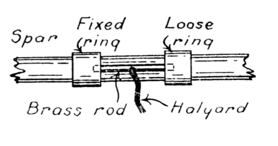
the halyards are fixed small pieces of brass wire 1/8 in. diameter by 3/4 in. long, having a small hole in the centre, through which the rope is passed and knotted at the end to prevent coming out. These pieces of rod fit into corresponding slots on their respective spars. At one end of the slot, overlapping it by about 1/8 in. is a fixed brass ring, and on the other end a sliding one. In order to secure the halyards to the spars, the piece of wire is placed in the slot with one end under the fixed ring, and then the loose ring slid over the opposite end to keep it in position. There are two halyards for the jackyard, and three for the topsail yard, the latter running through a treble block, as described for the Hilda. The easiest way of attaching the steel rope to hooks, etc, is to bend it round, whip it firmly, and then varnish, as the splicing 7-strand steel rope is very difficult indeed.
The running tackle is almost identical with that of the Hilda, but the new improved method of making fast the topsail boom and jackyard to their respective halyards, as already described, enabled the large jackyard topsail to be taken down with ease whilst the model was under sail, which is, perhaps, the most difficult manoeuvre to carry out in this class of boat.
Steering Gear
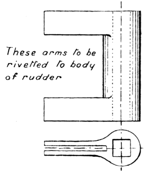
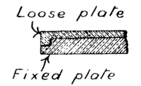
The steering gear used is that devised by Mr. Rhodes, and used on the Hilda [This was described in our previous issue. — Ed], but with two modifications. The first consists in having an annular recess round the edge of the lower or fixed disc, and a corresponding flange on the upper revolving disc, so that the one fits in the other. By this means the two discs are kept concentric with the axis of the rudder and with each other, and the oscillation of the loose one is more free. The second improvement lies in the connection between the rudder and rudder-post. The lower end of the rudder-stock is filed square, and fits into the square hole which is cut in the piece of brass on the top of the rudder, as shown in the drawing. This piece may be made as follows:
Select from the scrap heap a piece of brass or gun-metal, and cut a piece of it 1 3/4 in by 1 1/2 in by 5/8 in thick; from one edge saw out a piece 1 in long by 5/8 in wide. We have then a piece thus ∪. the arms of which are again slotted longitudinally to receive the rudder, so that the edge of the latter fits close to the body of the ∪-piece. The latter is now drilled 1/4 in through, and then the centre portion may be turned up between the centres, after which the hole is filed square, which is rather a tedious operation.
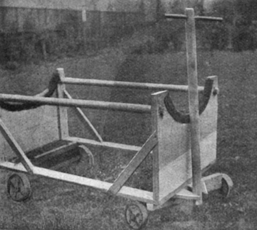
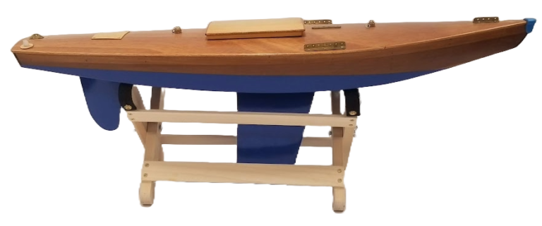
 Now, with a model of such dimensions and displacement, the launching and getting her out of the water was a problem of no little difficulty; and, seeing that it required three men to lift her, it was necessary to construct a special carriage for moving her about, which could at the same time be used for taking her into the water. Accompanying photograph will show the description of carriage which was made. The model was simply wheeled into the sea, and when in sufficiently deep water was lifted out and set on her course. Her draught at full load was 18 in. The wheels of such a carriage should be made of elm, 10 in diameter, 2 1/2 in thick with zinc tires, so as not to sink in the sand. All portions of the carriage should be well bolted together, and the wheels removable, thus enabling the carriage to be converted into a permanent stand, in which she can be placed for convenience and safety, whilst being conveyed in a case by rail, with no fear of damage. Needless to say that when conveying such a craft by rail, the fin, bulb, and rudder should be unshipped.
It may be interesting to know that if Mr. Theobald’s design and plan had been carried out, the displacement he estimated would have worked out at about 200 lb, whilst the actual displacement was 233 lb, including all tackle and gear, although the L.W.L. was increased to 6 ft 6 in.
The following are particulars of the various weights:
Weight of hull: 102 lb
Rudder and fin: 18 lb
Two lead bulbs (48 lb each) 97 lb
Spars, rigging, and tackle 16 lb
Total 233 lb
This model as above described is probably as large as can be sailed with any facility, unless accompanied by a motor launch. The actual speed obtained under the most favourable conditions was about 7.40 miles per hour, although it may be said that it was not deemed advisable to let her go too free, owing to the fear of not being able to overtake her. This speed, when actually estimated, is a very high one for a model, but the great satisfaction of sailing a boat of this kind is that neither wind nor water will stop her if her course be set properly.
The yacht was generally left afloat, anchored with a 5-lb anchor. With about 40 ft of line she rode without any difficulty a spell of nasty rough weather and high seas, which caused the local sailing craft to be hauled upon shore.
When riding at anchor the line should be made fast to the mast and then carried forward, passing through a lead attached to the bowsprit near to the stem.
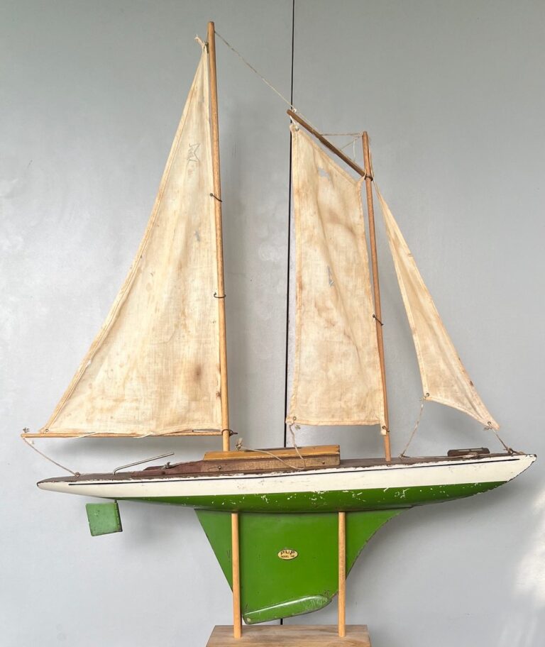
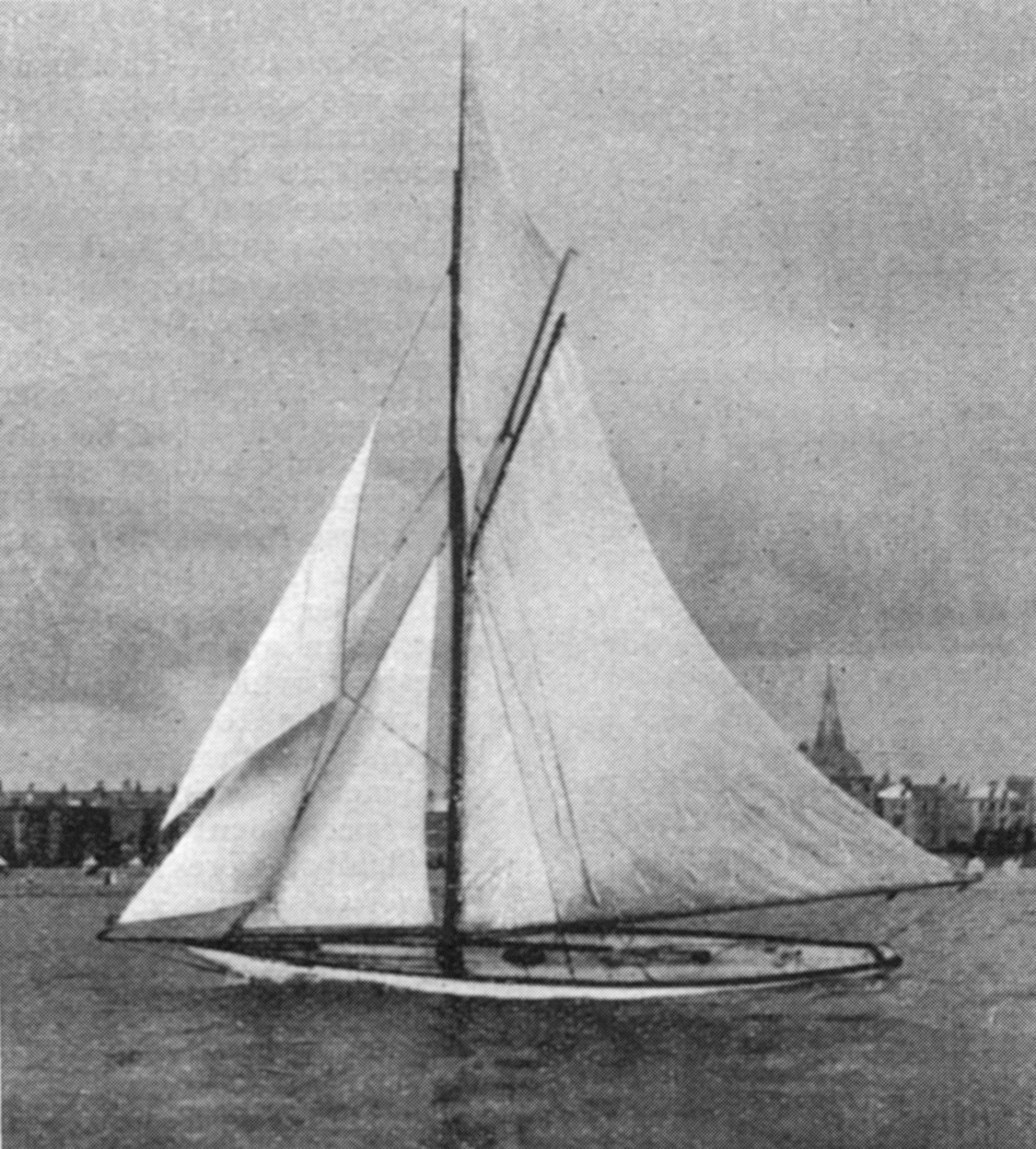
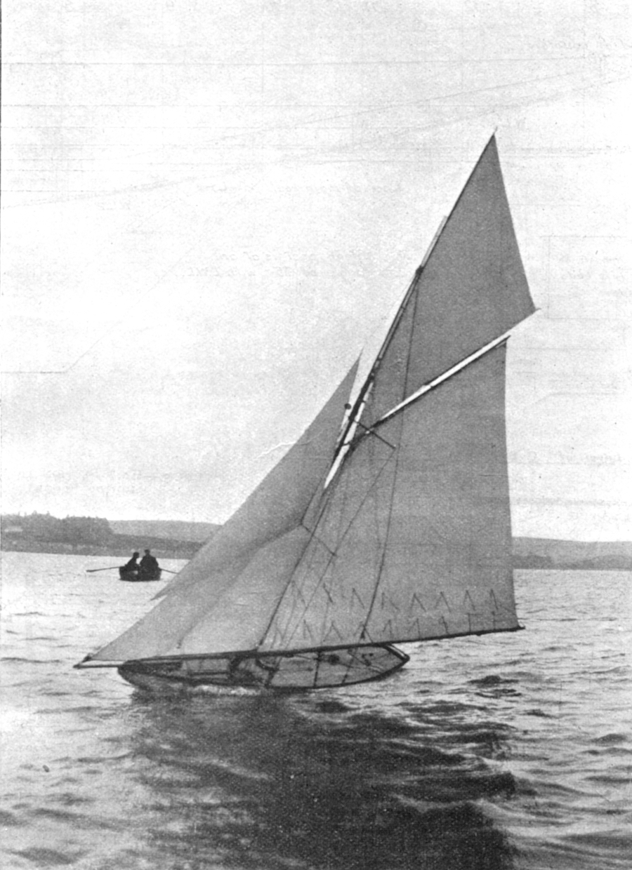
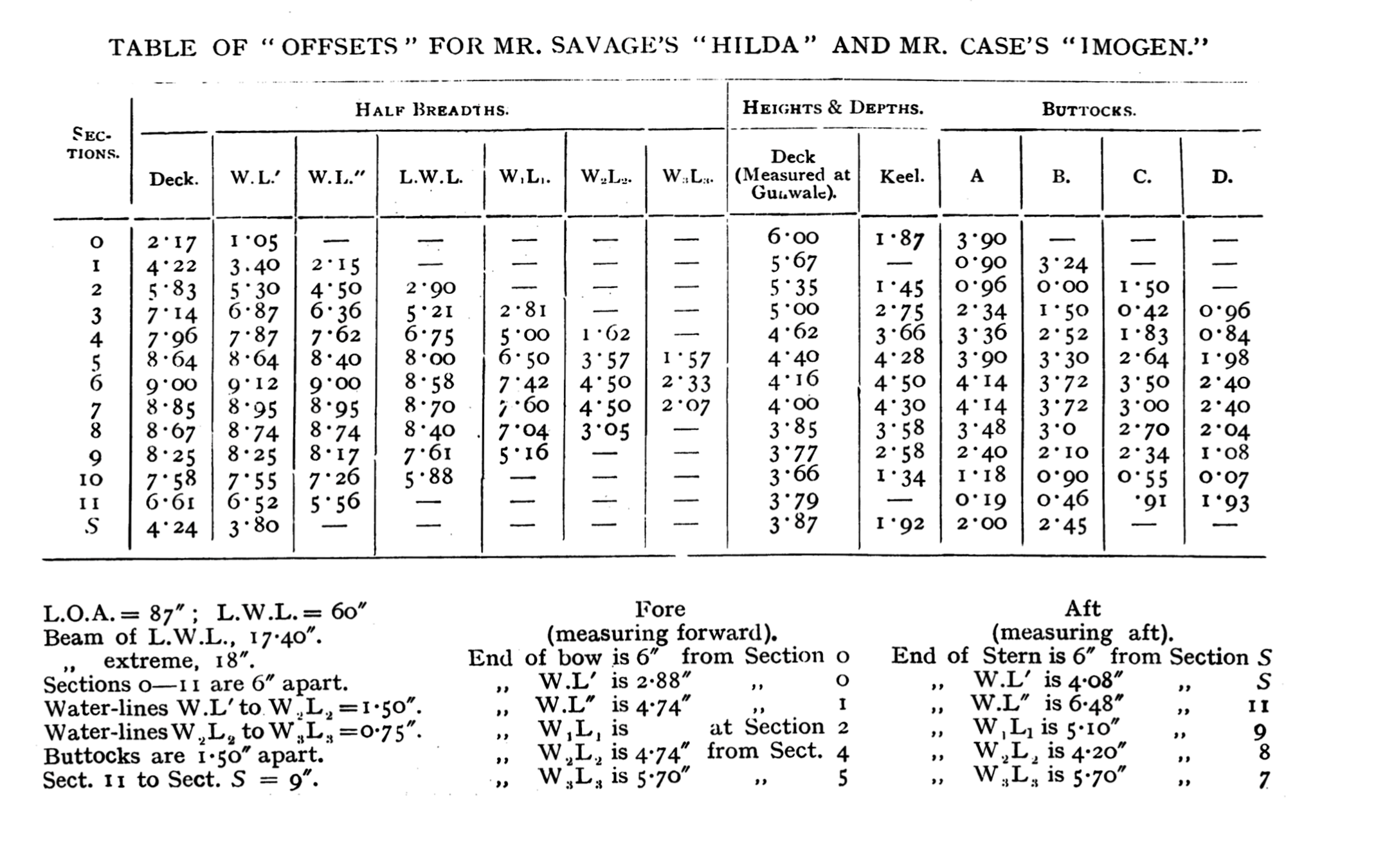
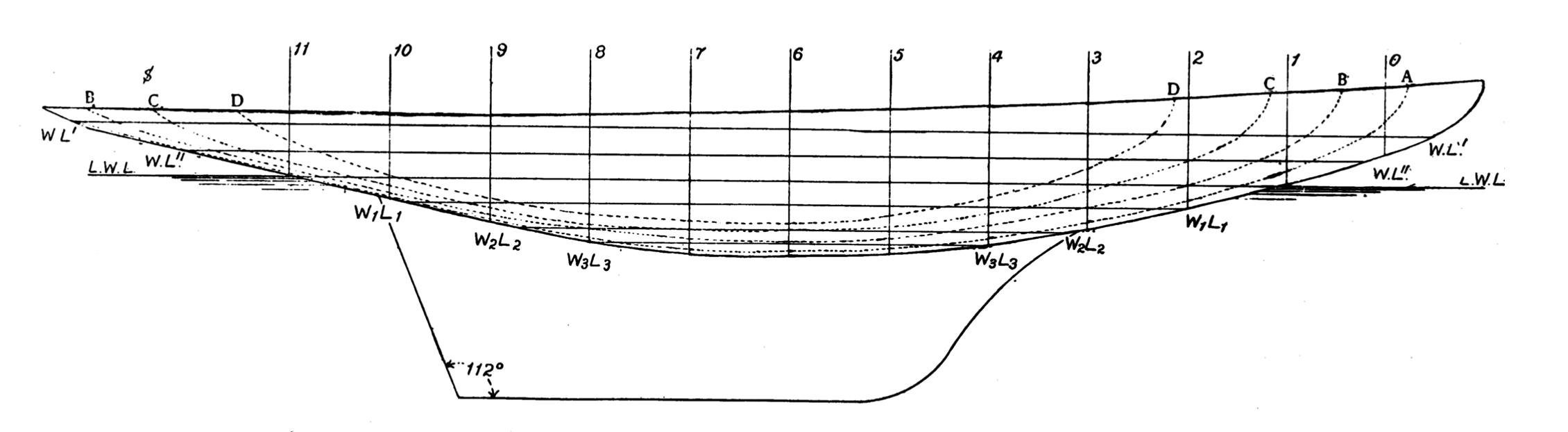
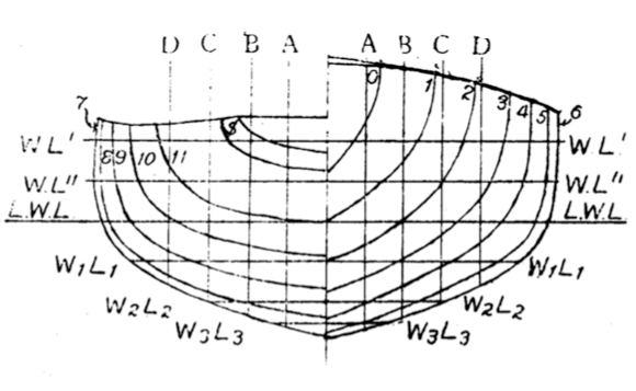
The third model shown—viz., the Imogen — is very similar to the Hilda; in fact, the hull and keel are identical, both in design and construction. The only difference lies in the sail-plan, the Imogen having a larger spread of canvas than the Hilda; in fact, slightly too large, as it is only in light weather she can carry a jackyarder, but her sail-plan is the prettier of the two, and before next year a few alterations will be made to enable her to carry her full suit of sails. At present she is fitted with ash spars, which are rather heavy, but these will be replaced by a set made of spruce, and possibly a hollow spruce mast from Dublin. Moreover, as her thick 9 SWG zinc fin keeps the centre of gravity rather too high, a new fin of aluminum bronze or phosphor-bronze only 15 SWG will be substituted, as being much lighter, offering less resistance, and enabling heavier bulbs to be fitted. Another mistake lay in the brass hatch, as this originally weighed 6 1/2 lb. It has since been reduced to 2 1/2 lb. Some of the fittings of this model are made of aluminum—viz., rigging screws, mast caps, goose neck, and portion of shattering gear. This proved to be a great mistake, as the action of sea-water on this metal causes great corrosion, and in the case of the tightening screws, unless carefully cleansed after every spin, causes them to bind on the brass screws, thus defeating their object. The model is painted outside with White Yacht Japan, which sets with an excellent surface, and the spars varnished with yacht varnish.
A few words in conclusion may not be out of place with reference to the best locality for sailing such models with ease and safety. If possible, a large bay, such as Weymouth or Sandown Bay should be chosen. These possess the advantage of having little currents, and are naturally protected from strong gales by the contour of the land. It is not only impossible, but dangerous to work such models in a seaway by one’s self, and a good oarsman should always be in the boat, who will have his work cut out in keeping up to the model, leaving the yachtsman free to work the sails, alter the sheets, and attend to the sailing.
Three golden rules are worth remembering when working a large model from a rowing boat or launch:
- Approach her from windward when any tackle, gear or sails require alteration, or when tacking.
- After completion of whatever operation is necessary, pass her aft before letting go.
- Follow her to leeward.
Unless these rules are followed a disaster is almost certain, either to the model itself or to the occupants of the rowing boat.
Given that the yachtsman has some idea of sailing there is no difficulty in making models like these keep on almost any course, provided the wind is constant.
It was found that in a fair breeze the Muriel, when close hauled, pointed higher than an 18-ft open sailing boat, and kept a true course within four points of the wind. The photograph of the Imogen shows how very close to the wind the Rhodes’ gear enables these models to be sailed.
Only practice and experience can, however, teach what can be got out of such a craft, but, given a fair breeze, a smooth sea and good muscles, no more enjoyable pastime can be obtained than sailing a sea-going model yacht.