Article, photos and illustration by John Henderson
Everyone who has built an R/C boat has faced the problem of how
to get the sails to trim over their entire wind angle range without stalling the servo at either extreme of its travel. For those who have not already worked out a formal procedure of their liking, I offer in this note a straightforward method that is easy and minimizes trial and error.
The variables under our control are:
- length of the servo arm.
- sheet attachment position on the boom.
- height of the boom above the deck (although this has a much smaller effect than the first two items).
- choice of servo – both the rotation range (the number of degrees through which it rotates) and the torque (which might affect how we use mechanical advantage).
Servo arm length
There are some practical limits. The length is constrained by the beam of the boat. If you want to use opposite-side arms of equal length on a single servo to control the main and jib, then the maximum length of each arm is a bit less than half of the beam after allowing for planking thickness and internal frames. If the arms for the main and jib are of unequal length, the sum of the lengths must be less than the beam. (Always check the swing for interference over its entire range.)
The length is also constrained by the available torque. The longer the arm, the more torque is required. The necessary torque depends on the sail area, wind strength, and friction on the sheet(s). I know of no easy formula for these factors. Look at the servos that have worked for similar boats. For the purposes of this article – which is about determining the lengths of sheet lines and arms – I will assume that a servo of adequate torque is available.
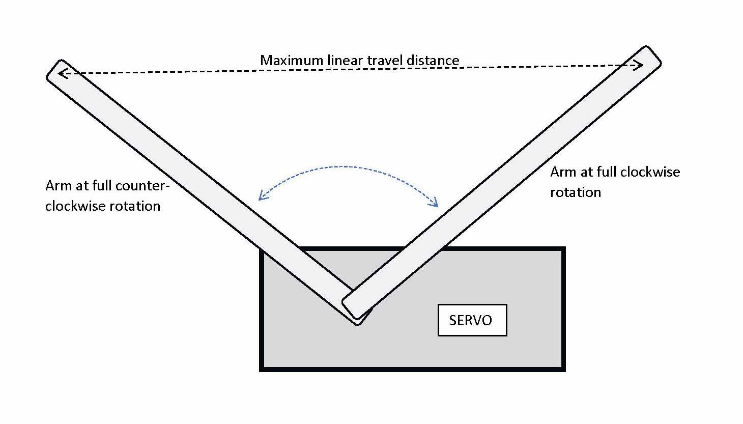
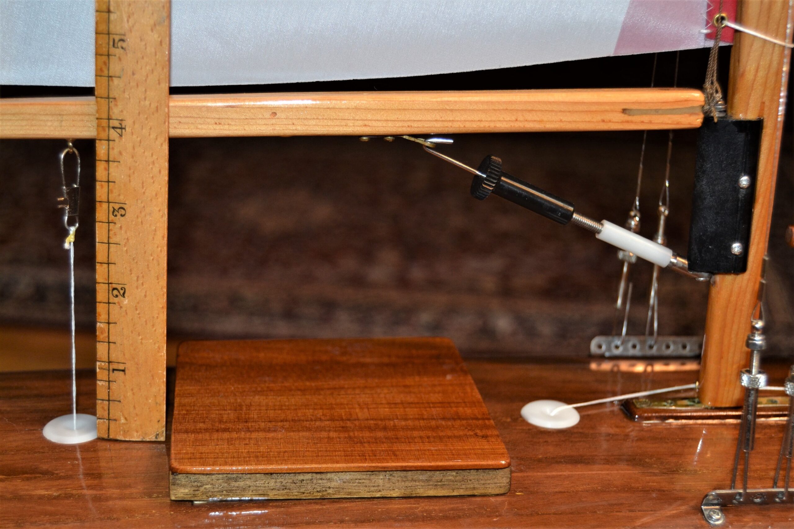
The first step is to measure the linear distance between the locations of the end of the arm at each extreme of its travel range. See Fig. 1 where the “maximum linear travel distance” is shown. The figure shows the swing arm positions for a servo with its (one-sided) arm at each extreme of rotation. The “maximum linear travel distance”, as shown in the figure, is the measurement needed, and it depends on the length of the arm and the rotation range of the particular servo. Note: this must be done using the transmitter to move the arm; it is not unusual for the servo to have greater available range of travel than is achieved using the signal from any particular transmitter. You also must account for how transmitter trim adjustments affect this range.
The amount of sheet line that you can pull in is directly related to the distance you just measured. If you attach the sheet directly to the arm, then the available amount of sheet length change is exactly the distance you measured. If you pass the sheet through the arm and then back to an attachment somewhere in the hull, then you can pull in twice as much sheet line – but this comes with a mechanical disadvantage of 2:1, so more torque is required. This is the “no free lunch” rule of physics.
Position of attachment to the boom
Having determined the maximum length of string that we can move with the selected servo and arm, we now find the boom attachment point that uses this length effectively. The attachment point is measured from the gooseneck “hinge”. Pick a distance (say, 12 in) and mark it with tape. Now, with the mast and boom installed and the boom in position at the height above deck that you expect for sailing, make 2 measurements:
- with the boom trimmed to close-hauled (near or at the boat’s centerline), measure the distance from the deck fairlead to the boom attachment point.
- with the boom all the way out (presumably hitting the shrouds or close to it), again measure the distance from the deck fairlead to the boom attachment point.
The difference between these two distances is the amount of sheet you need to pull in for that particular attachment point. Adjust the assumed attachment point, and repeat these measurements until you match the amount of string that the servo arm can move.
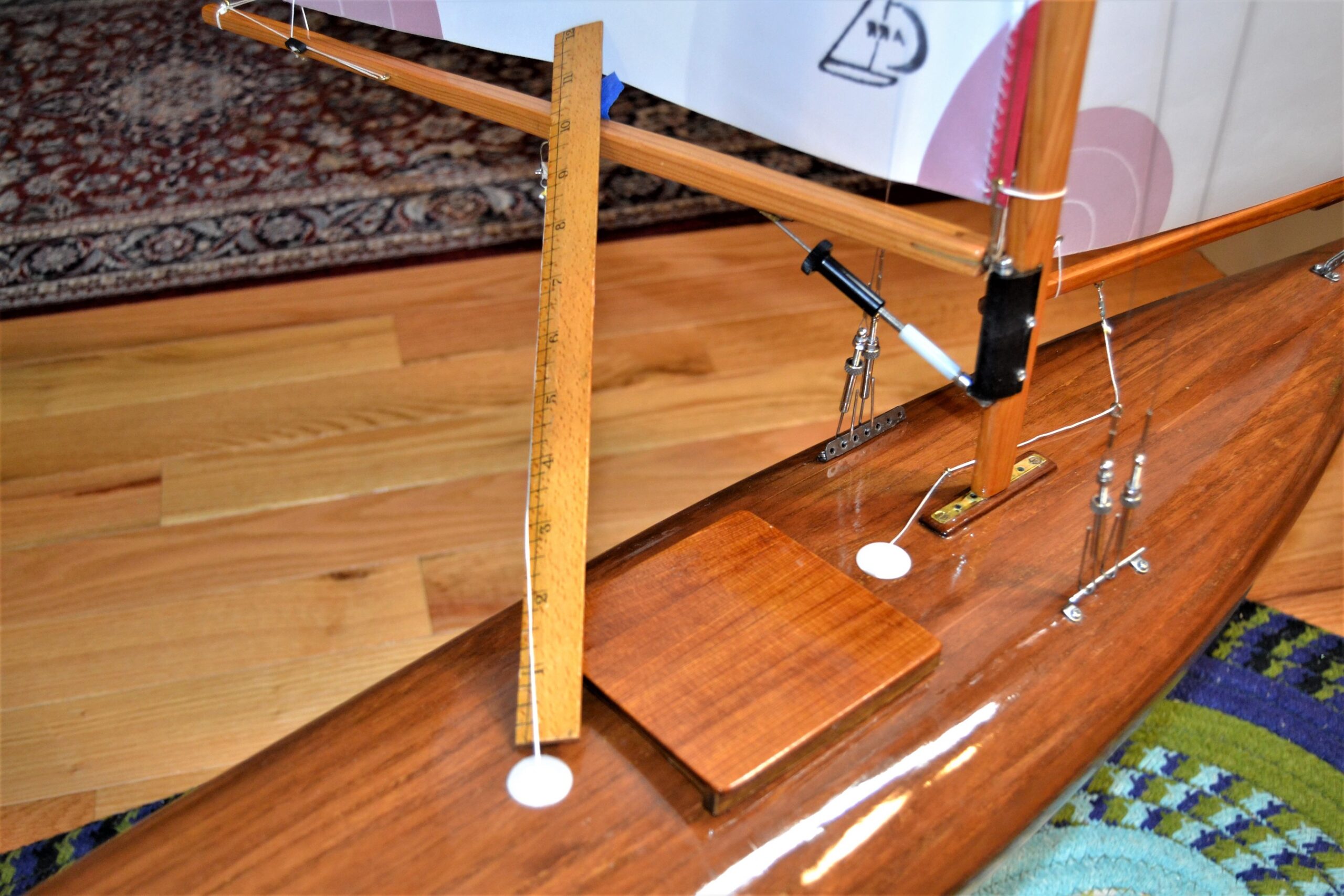
Fig. 2 A and B show the boom in each of these positions with the ruler in place to show the difference in sheet length. In this particular example, the close-hauled (inboard) measurement is about 3 3⁄4 in, and the outboard measurement is about 10 1⁄2 in, which requires the servo to move about 6 3⁄4 in of sheet line. I used a 2:1 arrangement with a wide-rotation sail servo and an arm length of about 2 in, which could move the necessary amount of line. (The boat is a fairly narrow Vintage 36, and I used equal-length opposite-side arms for main and jib, so arm length was a very real constraint.)
Some additional comments
The description above starts with a given servo arm and adjusts the boom attachment. You could just as well start with the desired boom attachment point and then determine the necessary servo arm length. It is often desirable, for example, that the boom attachment point be more or less directly over the deck fairlead and that fairlead’s location may be constrained by (for example) the deck hatch. In this case, you might start with the boom attachment location and work “backwards” to get the arm length.
If the boat is arranged so that the jib and main are controlled by the same sheet, then the attachment on the jib boom should be the same distance from its pivot point as the main is from the gooseneck. If the main and jib sheets are led to opposite sides of a servo arm that sticks out on both sides of the servo, then there is more flexibility because the arm lengths are not required to be equal. As a practical matter, it is often easier to make a symmetrical arm and equal boom attachment point lengths.
If you use the 2:1 arrangement, then you must find a suitable attachment point above or below deck for the “dead end” of the sheet. This point must be at or beyond the maximum travel of the swing arm, or else the full benefit of the 2:1 arrangement will be lost.
Note that if you use opposite sides of the servo for main and jib, then the respective sheets must be led from opposite ends of the servo – typically, the jib sheet through the deck forward of the servo and the main sheet aft.
Double-check your installation to be sure that the main and jib angles track each other over the full range of wind angles.