by Thomas Moore (1928)
The Lines
The lines of a boat are intended to show the outside surface of its form. To accomplish this object on the flat surface of a piece of drawing paper, it is necessary to use a little imagination. It is necessary to imagine that our boat is made of a transparent substance that may be cut in the vertical and horizontal direction and even in a diagonal direction by planes and that wherever these planes cut the outside surface of our boat they are distinctly visible as a continuous curved line. The lines of a boat show one-half of the boat, the other half being exactly similar. There are three views, the profile, the half breadth or plan, and the body plan.
The Profile
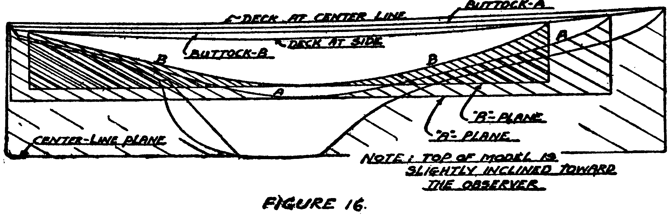
This view is taken looking at the boat as she stands upright on the table before us. We see the edge of the deck at the side, running in a shallow curve from the stem to the stern. This curve is called the sheer. Then we see the outline of the boat at the center line running from the stem down to the keel and up aft to the stern. This outline is called the profile. Now imagine a plane passed vertically down through the boat at the center line, through the keel, and extending from stem to stern. Then imagine several planes parallel to the first one but, let us say, one inch apart. They will cut the surface of our model in a fair, continuous curve indicated by A and B in Fig. 16. These are called buttock lines.
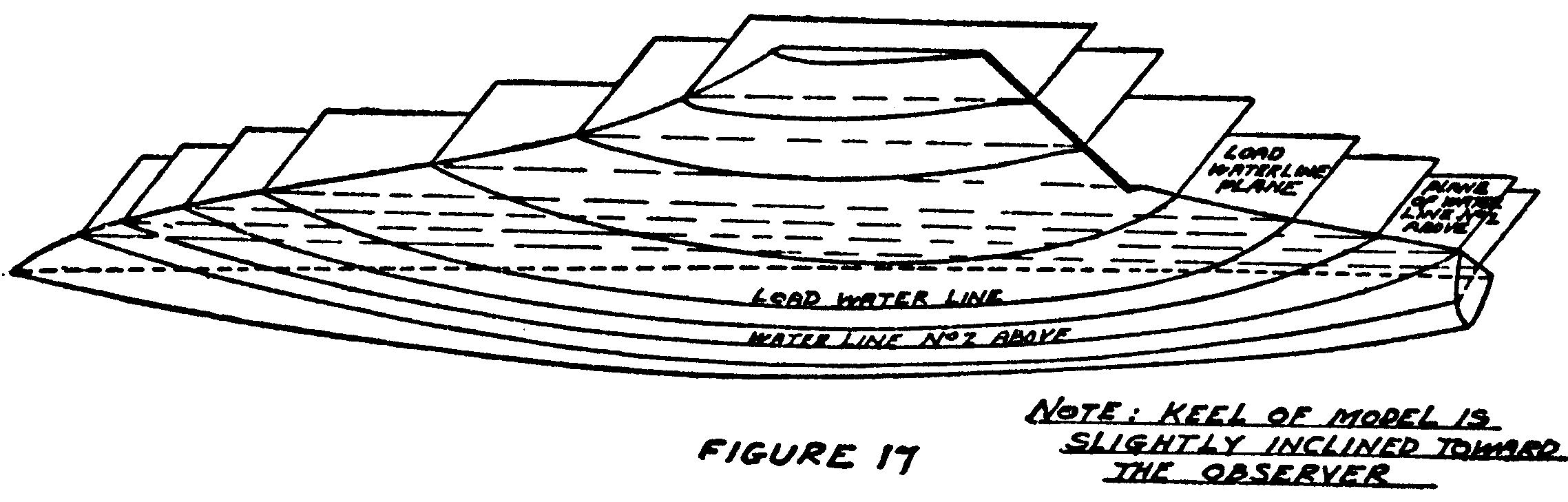
The Half Breadth
This view is taken looking down at the boat as she lies bottom up on the table. The first distinct curve which meets our eye is the deck line sweeping out in a wide curve from stem to amidships and then aft to the stern. Now suppose the boat is painted white above the water line and green below. We then also see a shorter curve extending from a point on the center line below the stem head to a similar point on the center line near the stern. Suppose that where the white and green meet marks the line at which she floats in the water with all sails, spars and gear on board. Then this line will be the load water line (LWL). Pass planes through the boat parallel to the load water line both above it and below it and you have a series of water lines appearing as shown in Fig. 17.
The Body Plan
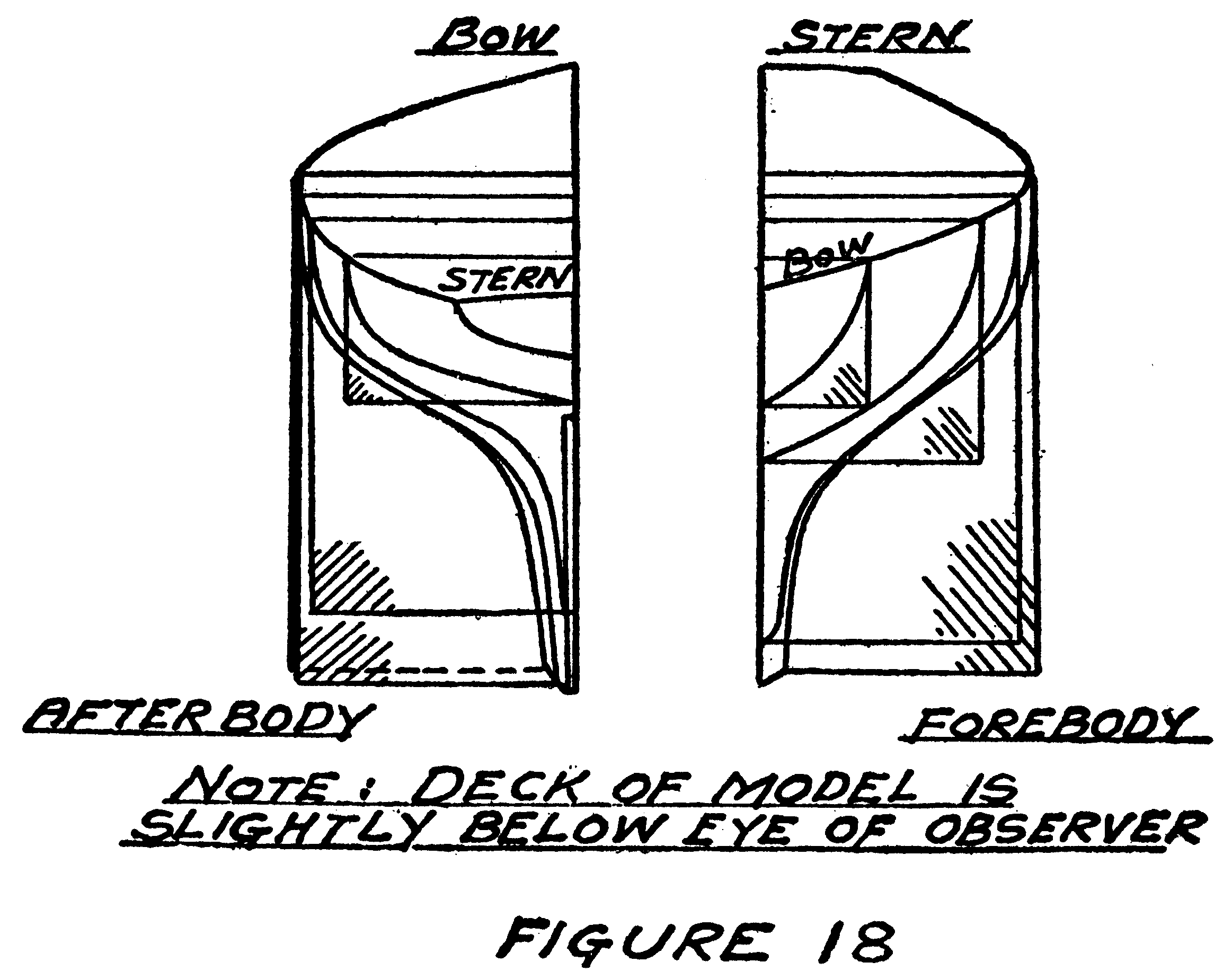
This is a view with the body of the boat standing upright and looking at her dead on end. We see first, the vertical line of the stem extending downward to the keel. Then we see the side of the boat extending from the deck amidships downward and curving in to meet the keel at the bottom. We really see the line formed by the intersection of a vertical plane passed through the boat perpendicular to the base line and to the center line, as in sketch Fig. 18.
The curved lines formed by the intersection of the surface of our boat and the above mentioned planes are called sections.
It will be noted that in the case of water lines, buttocks and sections, lines appearing curved in one of the three views are straight in the other two views.
Laying Off
The prospective model yacht builder must either obtain a suitable set of lines or work out an original design and prepare the lines himself. In either case, it is necessary to study the characteristic hull form of the different types of yachts and to endeavor to acquaint himself with the various elements which, incorporated in the design, contribute the qualities of speed, stability, and balance.
First, let us take the case of the prepared design, which will probably be chosen from one of the well known monthly magazines devoted to the sport of yachting. The design, as printed in the magazine, will no doubt be on a small scale, and the problem is to enlarge it to the size required for the model. There are two ways of doing this. If it is simply desired to enlarge the lines a given number of times-let us say, six-the way to do it is to lay out the framework of water lines, sections and buttock lines with just six times the spacing shown in the original drawing. It is best to use the small bow-spring dividers for making this spacing.
The set of lines in Fig. 19 is given as an example.
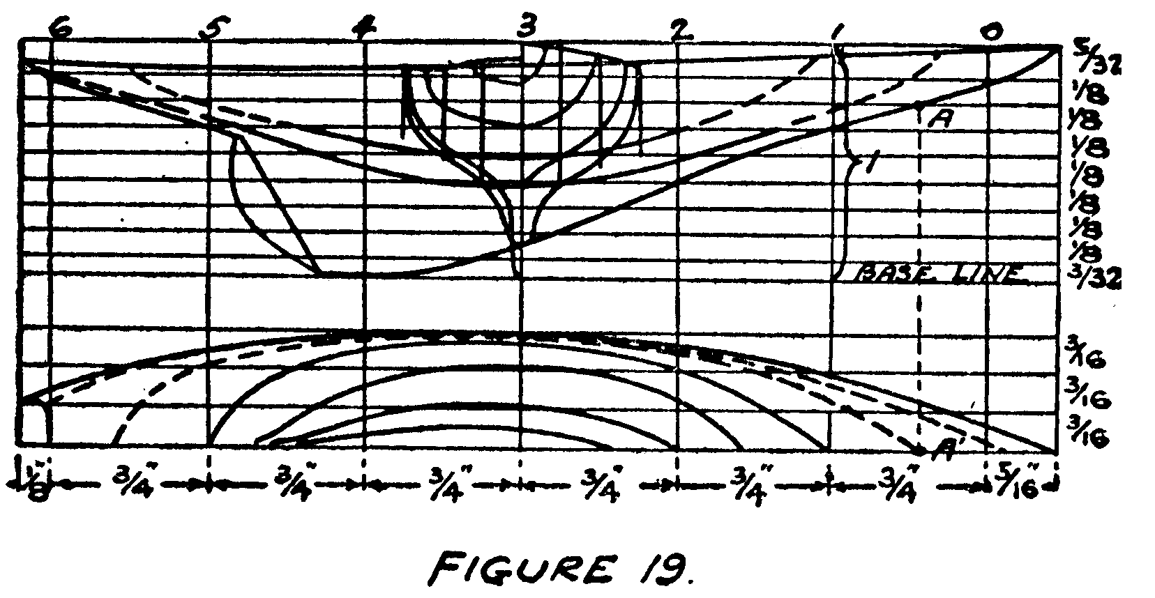
It is now desired to enlarge the above set of lines six times. Fig. 20, printed on a greatly reduced scale, shows how this is done. We first construct our framework of water lines, buttock lines, and sections. As will be readily seen, the water lines in our enlarged drawing are spaced six times the distance apart that they are in the original small drawing. The same with the buttocks and sections. The next problem is to get curved lines of the profile, half-breadth plan and the body plan correctly superimposed on our large scale framework.
[The text that follows is not completely obsoleted by the ability to enlarge drawings using photocopying equipment. You must remember that old drawings and old publications will inevitably have shrunk or otherwise distorted over the years. It is not at all unusual to have an old full-scale blueprint that has shrunk 5% or more horizontally and be exactly to dimension vertically. A typical way of fixing this is to cut the drawing up at the section lines, lay the pieces out at the exact section spacings, and then redraw and refair the lines on tracing paper. Once you begin doing that you are just about where Moore is when he starts his discussion of scaling up. —ED]
We will start by obtaining points for the sheer line. Measure the distance on the small drawing, between the base line and the sheer line on Station No. 1 by means of the dividers. Set this distance up from the base line on No. 1 Station of the large drawing six times, and make a little dot. Repeat this process on the other four stations and at the extreme ends of the boat. We now have a series of dots through which we may draw a fair, continuous curve which forms the sheer line of our enlarged drawing.
It may be well to state here that in drawing these long curves we will need several long, limber strips of wood, of approximately square section, called splines or battens which may be held in place on the plan by means of lead weights called dogs.
[The weights are also called “ducks” or “whales.” They are somewhat hard to find these days. —ED]
These splines and dogs may be made at home or they can be purchased in a store where draughtsmen´s supplies are sold. Splines may also be obtained made of hard rubber or celluloid in lieu of wood. These are useful on the more abrupt curves. If these regular draughtsman´s materials are not available, very good results may be obtained by ordinary home-made pine battens held in place by flat irons, pins, or willing hands. It is obvious that several battens, ranging in thickness from 1/4 inch to 1/16 inch will be useful, the thicker battens to be used on the flatter curves and the thin battens on the more abrupt ones.
[Masking tape also works well as a way of holding down splines or battens. —ED]
Now to tackle the profile. We measure up on each section on the small plan the distance above the base that the profile crosses the sections, and then transfer this distance six times above the base on our large plan and make a dot. A curve drawn through the dots gives us the profile on our large plan and we begin to see how big our boat is going to be. Now let us turn to the half-breadth plan and get our water lines drawn by measuring up on the sections in just the same way as we did for the sheer and profile. The actual terminations of the water lines may be obtained directly from the profile by dropping perpendiculars down to the center line of the half-breadth from the point where the profile crosses the particular water line with which we are dealing. Take the water line just above the load water line (Fig. 20). A A´ is the forward perpendicular and A´ is the forward termination of this water line. The after termination is found in the same manner.
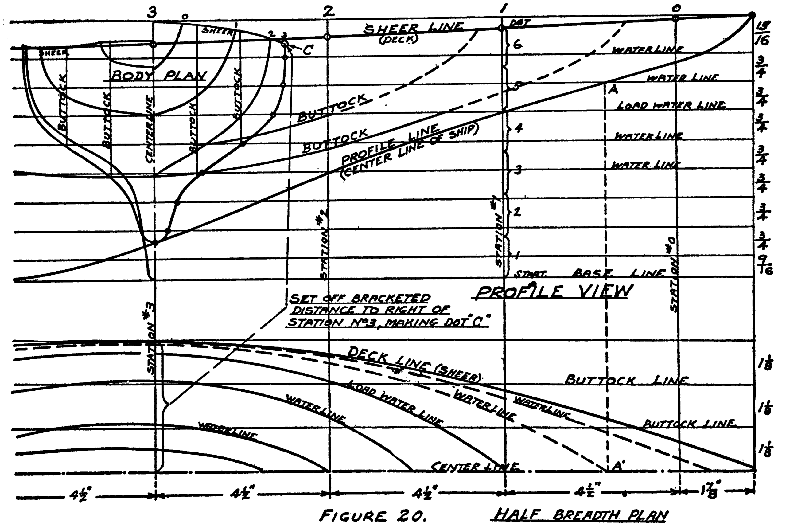
The sections should now be drawn in. It is no longer necessary to refer to our small plan unless we wish to do so as a check. We can take our plain dividers and, using Section No. 3 as a center line, we can set off the sections in the forebody to the right of this line and the sections in the afterbody to the left of the line. Measure directly from the half-breadth in the large plan the width of the deck (from the center line up to the curve) on Section No. 3. Set this distance out to the right from Section No. 3 in the profile. Now, as the height of the sheer above the base varies forward and aft we must also be sure to set this half-breadth measurement at such a height as to have it correspond with the height of the sheer line at Section No. 3. We will get a point at C which fulfills the above requirements. It is now simply necessary to set out on the several water lines in the profile, the widths of the corresponding water lines at Section No. 3 taken from the half breadth. This gives us a series of rather close spaced spots through which we may draw a fair curve freehand. There are, however, ship draughtsmen´s curves for this work and it would help the accuracy and finish of our design if they were employed. It will be necessary to piece these curves together, as it is very rarely possible to find even among a whole set of these ship curves one that will lend itself to drawing an entire section, and have the line go through all spots. The other sections may now be drawn as described for Section No. 3, and we have then the body plan complete. Our drawing is apparently sufficiently complete to allow us to proceed with the construction of the model, but can we be sure of its accuracy! It is inevitable, in the process just described, that small errors will be made in transferring measurements, and these enlarged six times have made a few of our spots appear uneven We have endeavored, in drawing our lines through these spots, to strike a general average, or to adhere to the most spots which gave us a fair curve. It is now necessary, to insure the symmetry and accuracy of our model, to obtain complete agreement between the sections in the body plan and the water lines in the half-breadth plan. Any disagreements of this nature are best shown up by introducing a few buttock lines and three or four diagonals. The purpose of these lines is principally for fairing our hull, and their general nature has been previously discussed. By study of a set of published lines shown in Fig. 4 and from the above description of transference of “spots” it is believed that the reader can master the use of these lines without further explanation. It will be noted that the buttocks are really very similar to water lines, but are run vertically instead of horizontally. The diagonals are run at varying angles between the vertical buttocks and the horizontal water lines, but the general idea of a diagonal is to have it approximately perpendicular, so far as possible, to the surface it intersects. Beside the property of fairing the outside surface of our hull, the water lines, buttocks and diagonals all combine to tell us about the form of the boat. As soon as we have learned to interpret the form of the boat from these lines we can better understand the relation they have to speed, stability, balance and, last but not least, beauty.
The Offset Table
In the case of large vessels constructed in a ship yard, a full sized set of lines is made on the floor of a large building called the “mold loft.” These full-sized lines are taken from the drawing office set of lines which have been drawn to a scale of, say, 1/4 inch to the foot. A table of offsets of the lines of the vessel on sections, water lines and buttocks with a sketch of the conformation of the profile of stem and stern is furnished the mold loftsmen who now “lay down” the lines of the vessel, full size, on the mold loft floor.
In large vessels the measurements are expressed in feet, inches and eighths of an inch, and an architect´s scale is used in taking these measurements, which are expressed, for example, 31-10-5, which is 31 feet 10 5/8 inches. The following figure (Fig. 24) gives the mold loft offsets of the set of lines shown in Fig. 19.
[This table contains errors. Drop to the bottom of the article to find a corrected table and drawing courtesy of Paul Remke —ED]
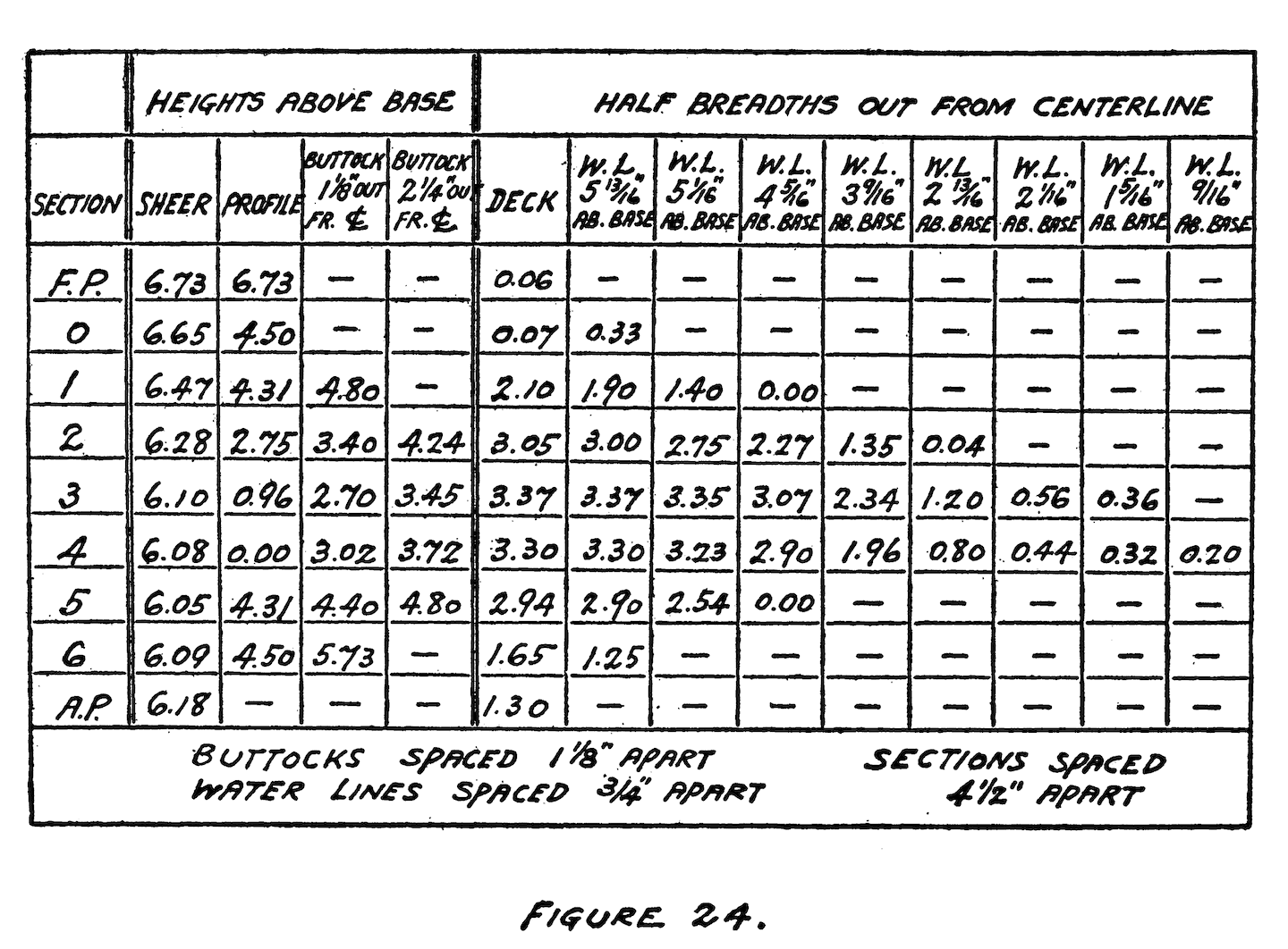
It will be noted that the offset table is in two principal parts: the height above the base of lines appearing in the profile and the half-breadths, or distances out from the center line of lines appearing in the half-breadth plan. Take first the heights above base. Under the heading “Sheer” are given the height of this line at bow or fore perpendicular, at each section, and at stern or after perpendicular, above the base. If we have our framework accurately drawn up we can set these heights on the respective stations, draw a line through the spots and thus we have the sheer line in our new enlarged drawing. Now follow the same procedure with the buttock lines and profile.
Now turn to the half-breadth part of the offset table. Under the heading “Deck” are given the distances out from the center line of the deck at side on each section. Set these distances on their respective stations on our new enlarged drawing, run a line through the spots and we have our deck line. Follow the same procedure with the water lines, each in turn.
The process of fairing up between the lines of the profile and half-breadth plans should now be gone through as previously described while we are drawing in the sections on the body plan, the latter being made from measurements taken directly from the profile and half-breadth of the large plan we have just drawn.
Some Hints in Regard to Design
The model yachtsman will only obtain the greatest amount of enjoyment from the sport when he has learned to design his own model yacht, as well as to build and sail it. Although the first attempts at designing may not, in competition with the products of experienced designers, prove very encouraging, it is very evident that true insight into the art can only be gained in this way. In each successive design the imperfections noted in the sailing of models built to previous designs can be remedied, and at last, very near perfection, so far as pertains to matters of design, can be reached. If at the same time like improvement has been made in construction and rigging details and in handling, proficiency in the sport may be attained and the model yachtsman may feel the confidence in his boat and himself that he should have in competition with other proficient yachtsmen.
Before the urge to create a new design comes to us we generally have had a number of thoughts running through our heads along such lines as these: “If I make my next boat a little longer and narrower, I will get less resistance at high speed, hence she will be better in strong breezes where my present boat is a little weak,” or, “My present boat has such an excessive amount of displacement that she is handicapped when in competition with newer boats. I will design a new boat with less displacement to trim these fellows that have been beating me.” Then we get out a pencil and a piece of paper and make some tentative freehand sketches of the new creation. Eventually we arrive at the time when we are standing before our draughting table on which is a nice clean sheet of cheap but durable detail drawing paper, ready to elaborate upon our little pencil sketch and produce a design which shall be the last word so far as our experience goes.
It will be remembered that in connection with the determination of the form of our hull, the qualities of speed, stability, balance and beauty were mentioned. Of these qualities balance is undoubtedly the prime requisite, for no matter how speedy, or stable, or beautiful our craft is, unless she is able to sail consistently on a given course she will not be able to compete successfully with slower craft that can. And to sail consistently on a given course the boat must have balance in light airs, in moderate breezes and in heavy winds.
Balance
Assuming that both sides are alike, the model will be in balance when upright and at rest, floating at its designed load water line in calm water. The model will then be acted upon by two forces which are equal and, as they are acting in the same line but in opposite directions, no motion results. (Fig. 25.)
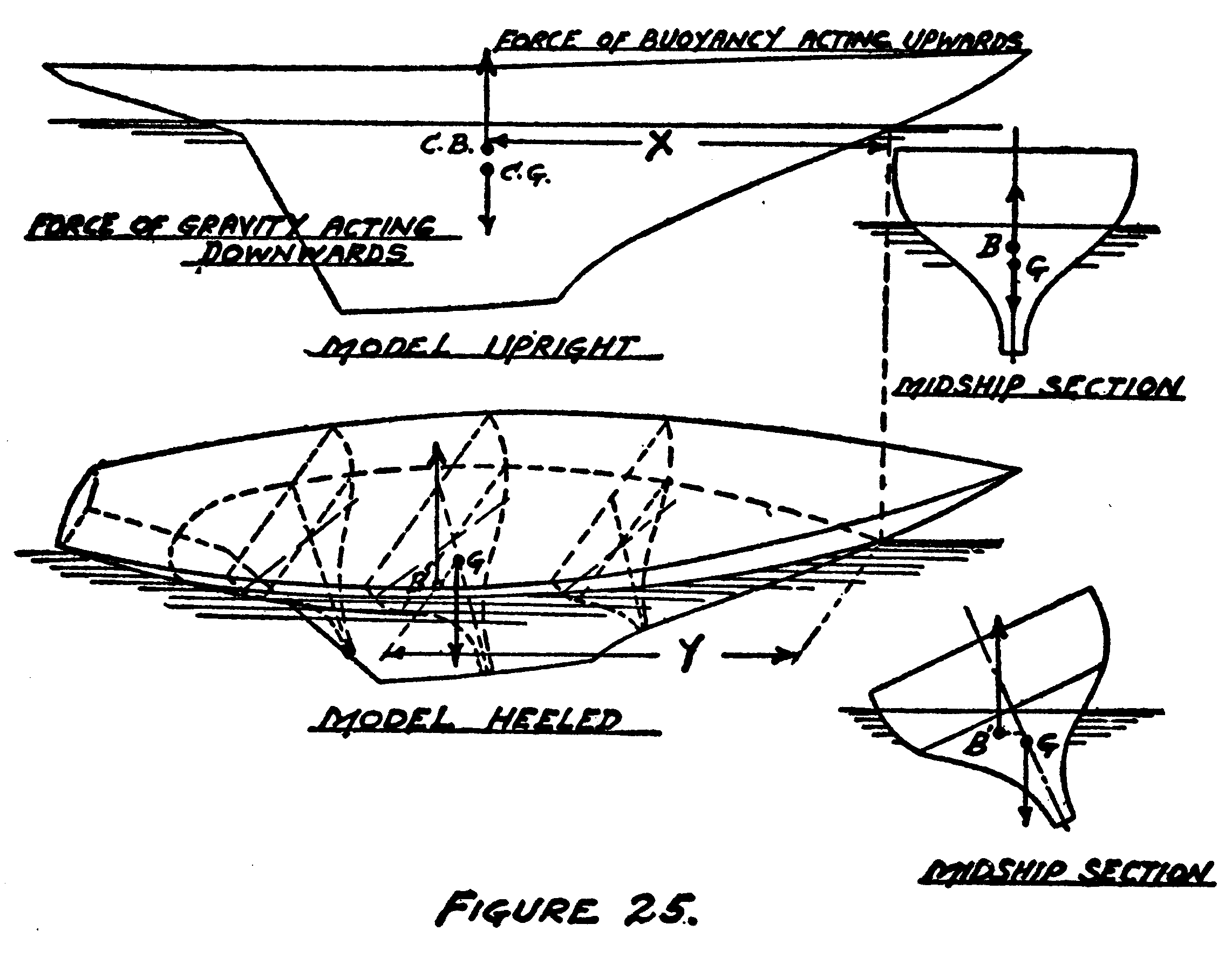
The weight of the boat W acts downward through the center of gravity CG of the model and is balanced by upward force of buoyancy B concentrated at the center of buoyancy CB.
Now suppose the model to be heeled over at an angle of, say, 35 degrees. It is obvious that there has been no change in weight of the hull, nor, with respect to the hull itself, in the position of center of gravity. There has, however, been a considerable change in the form of the immersed portion of the hull and it is entirely possible that the position of the center of buoyancy has moved.
Looking at the lower midship section of Fig. 25, we note that the center of buoyancy has made a lateral movement to B´ which places it in a vertical line with the center of gravity G. The model is at rest in an inclined position, held at the angle by an outside force. The point we now wish to bring out in the present discussion is the change in the fore and aft location of the center of buoyancy. If it has moved forward any considerable amount it means that our model has come up at the bow as she heeled over. If the center of buoyancy has moved aft it means that she has come up by the stern and that the bow has dropped. These changes of trim, as they are called, are very undesirable accompaniments of heeling as the model tends to lie at an angle to the direction of sailing which destroys the quality of balance, so essential in keeping a straight course.
To avoid these changes of trim in the heeling model it is necessary to design the ends of the boat to suit each other. As a general example, sharp V-shaped forward sections should be balanced by deep V-shaped sections aft. Full or U-shaped sections forward permit generally fuller sections aft, and flat sections forward call for flat sections aft.
Design
In all we have said in the foregoing, it is evident that our boat should be well proportioned in a fore and aft direction if she is to do well. In other words, the body of the boat should be developed in fair, flowing curves from stem to stern without local bumps, hollows, or flat places anywhere.
Suppose we have roughly determined upon a boat, of the following general dimensions:
Length Over All: 46 in
Length on LWL: 33 in
Breadth: 9 in
Draught: 9 in
Displacement: ~14 1/6 lb (380 in3)
We may lay down our drawing on a scale of 1/2 inch to the inch, which will be a convenient size for the purpose of study. On the above scale the load water line measures 16 1/2 inches. At the lower part of the drawing, draw a horizontal line AB representing the center line of the boat in the Half-Breadth Plan. On this line lay off the length of the water line, 16 1/2 inches, and divide this distance into eight equal parts, 2 1/16 inches each. At each of the nine points of division thus made, erect perpendiculars to the line AB, and number these perpendiculars, beginning at the right, 1, 2, 3, etc. These perpendiculars represent the sections. Above the line AB, at a distance somewhat greater than half the breadth of the boat, draw the horizontal line CD as a base line at the bottom of the keel. The draught of water is 9 inches which on 1/2-inch scale is 41/2 inches, so draw at this distance above the base line another horizontal line EF for the load water line.
Fairing the Lines
The correction of these discrepancies and the process of making all intersections in one plan agree with those in the other two-I speak now of the profile, half-breadth and body plans- is called fairing. It is not possible to describe this process in detail by means of words, but if we have mastered the preceding text and have observed closely the method of bringing our plan up to its present state, we shall be able to fair the lines and make them accurate. Do not be afraid to introduce new diagonals, buttocks and water lines in any position where they will be an aid to the fairing process. The two main points to be remembered are: first, the lines of the hull must be fair; and second, the sheer, body, half-breadth plans and diagonals must agree in all corresponding measurements.
Calculating Displacement
We should now check over the question of displacement by drawing a new curve of displacement which shall take in the whole underwater portion of our hull and by getting the area of this curve, find our total displacement. We should first find the areas of our underwater sections on the body plan, keel and all, and set them up on the proper ordinates below the line AB. We find, as might be expected, that amidships, where the keel is located, we are running quite far outside our original curve of areas, and this, of course, is due to the added displacement of our keel. The area of the sections can be obtained by means of a machine called the planimeter, obtainable in most engineering offices. Possibly one can be borrowed for a few hours. Failing that, however, we can obtain quite a close figure by the use of cross-section paper, counting the squares enclosed within our section curve and the center line and load water line. When our final curve of displacement is drawn, we proceed to find its area. Using Simpson´s Rule, we first find the length of the ordinates to the curve on Sections 1, 2, 3, 4, 5, etc., and multiply them by a series of multipliers 1, 4, 2, 4, 2, etc. The products we multiply by the number of stations distant from No. 1. The sum of the first series of products multiplied by the station spacing of 2 1/l6 inches and then by 1/3 gives us the volume of one-half of the boat. The sum of the second series of products multiplied by the station spacing and divided by the sum of the first series of products gives us the distance of the center of buoyancy from Station No. 1. The following is an example of the calculations based on our design:
| Sta. | Area | X | Product | X | Moment |
| 1 | 0 | 1 | 0 | 0 | 0 |
| 2 | .25 | 4 | 1.00 | 1 | 1.0 |
| 3 | 1.09 | 2 | 2.18 | 2 | 4.36 |
| 4 | 2.10 | 4 | 8.40 | 3 | 25.20 |
| 5 | 2.93 | 2 | 5.86 | 4 | 23.44 |
| 6 | 2.75 | 4 | 11.00 | 5 | 55.00 |
| 7 | 1.90 | 2 | 3.80 | 6 | 22.80 |
| 8 | .66 | 4 | 2.64 | 7 | 18.48 |
| 9 | 0 | 1 | 0 | 8 | 0 |
| 34.88 | 150.28 |
1/3 × 2 1/16 × 34.88 = 23.98 in3 for one side
23.98 × 2 (for both sides) = 47.96
Now, as the scale is 1/2 inch = 1 inch, the volumes are compared as the cubes of linear dimensions. Accordingly, we must multiply 47.96 by 2 X 2 x2 or 8 to get the volume of our boat:
47.96 × 8 = 383.68 in3
383.68 × 0.037 = 14.19 lb
(1 in3 of sea water = 0.037 lb)
Now to complete our calculation we wish to find the fore and aft position of the center of buoyancy. This information is useful as it enables us to determine where to locate the lead ballast.
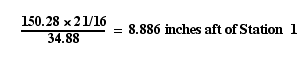
The sum of the moments about the Station No. 1 is 150.28. Dividing the sum of the moments by the sum of the areas and multiplying by the common interval givesMultiply by 2 for our scale and get 17.772. The Center of Buoyancy is therefore 1.272 inches aft of Station 5.
Center of Gravity
In the foregoing we calculated the displacement and found the position of the center of buoyancy. We must now determine the amount and position of the lead ballast that the boat is to carry.
We have a total displacement of 14.19 pounds. This is also the total weight of our boat with rigging, fittings, ballast, etc. It is possible, by careful workmanship, to construct a bare hull of the size of our boat weighing about 3 3/4 pounds. The deck, rigging, fittings, etc., will probably weigh about 1 3/4 pounds. We can assume a line for the top of the lead about as shown on the plan and then figure the volume in the same way we figured the volume of the under-water portion of the hull. The line of the top of the lead can then be shifted to make the volume of the lead and hence the weight (using .41 pounds per cubic inch as the weight of the lead) what we want and to place the center of gravity of the lead in the proper position. We should make a rough calculation for the fore and aft position of the center of gravity of the boat. This will insure that the trim of the boat will be as shown by the plans. We begin by assuming that the position of the center of gravity of the deck and hull is 2 inches aft of Station No. 5, and that the center of gravity of the rig is 1 inch forward of Station No. 5:
|
Part
|
Weight
|
CG from Sta. 5
|
Moment
|
It will be noted from the foregoing that a position of center of gravity of lead has been assumed such that the total of the moments of the weights of the several parts of the boat about Station No. 5 is equal to the moment of the weight of the whole boat acting through the center of buoyancy about Station No. 5. This is done to bring the center of gravity of the complete boat and the center of buoyancy in the same vertical line. As explained previously, this produces equilibrium at the designed trim.
The Sail Plan
We have now completed our design except for the sail plan. It is assumed that the prospective builder will want to adopt a rig which has been found to be the most effective for model racing yachts. This rig is the jib-headed sloop rig with single jib. The next question is area. The present design has been tried out with about 1,030 square inches, and has been found well able to carry this amount in open-water sailing. One should have as much as .25 of the total area in the jib. We must next determine the dimensions of our sail. [This is usually limited by class rules. –EB] The length of the boom is generally between 1/3 and 1/2 the hoist of the mainsail. The mast should rake slightly aft. The boom may be approximately parallel to the water line about 2 1/2 inches above the deck and raking slightly upward at the outboard end. The leech, or outer edge, of the mainsail should have a slight convex curve. The jib should be about the proportions shown. If it is any higher and narrower it is often difficult to make it set flat, and if it is shorter and broader it is not so effective. The jib should set quite flat with only a slight fullness near the jib stay. The leech, or aft edge, must be flat without any curl in it. This result is obtained by the use of battens in the leech and by proper rigging the jib.
Sail Plan and Center of Effort
We must now calculate the area of our two sails as shown in Fig. 15. They are triangles and the area is found by multiplying 1/2 of the height by the base. We must also find the center of effort of each sail and the position of the combined center of effort of the two sails. The center of effort is the point about which the pressure of the wind on the sail may be supposed to concentrate. It may be readily imagined that this supposition is largely theoretical, as with the wind meeting the sail at different angles when the boat is beating, reaching and running, the center of effort moves forward or backward in a manner yet to be determined. However, as a relative means of obtaining sail balance the use of these centers is justified. To obtain the center of effort of a triangular sail, bisect the two sides and draw lines from the corners opposite to the points of bisection. Where these lines cross will give the position of the center of effort.
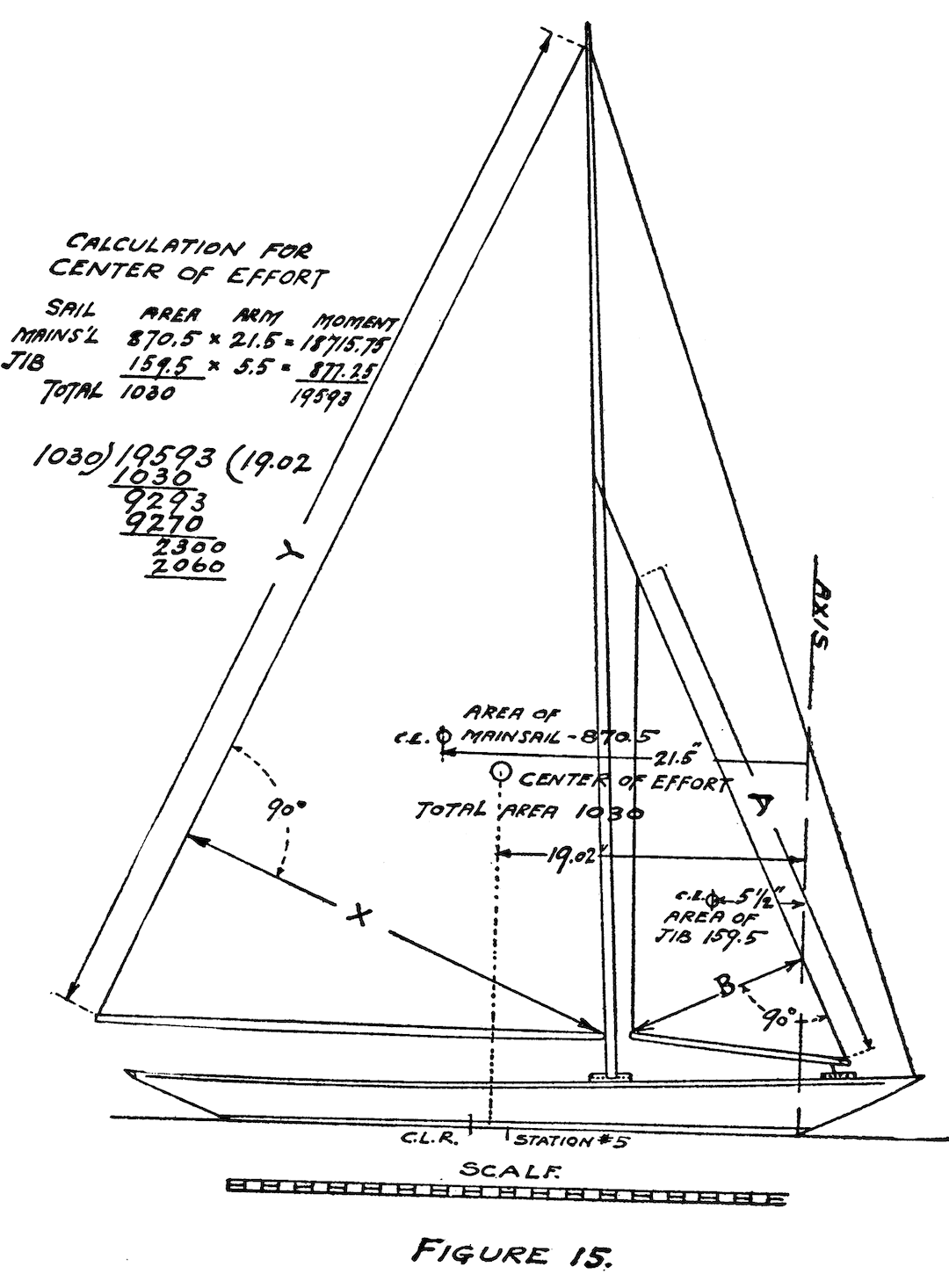
If the mast is raked aft, it is best to take an axis perpendicular to the water line. The sail plan of Fig. 15 will give the method employed which, with the foregoing text, will enable the prospective builder to readily follow the several steps. There is a point to remember. If an axis or reference line is chosen which lies between the jib and the mainsail, the arm and consequently the moment of one sail or the other will be minus, while the other is plus.
[A more detailed set of instructions for finding the geometric center of effort can be found here. –EB]
Center of Lateral Resistance of Hull
When the position of the center of effort of the sails has been determined, we now return to the hull design, and taking the profile or outline of the under-water portion, we figure the fore and aft position of the center of this area considered as a plane figure. To do this we measure on each station, beginning with the one at the for. ward end of the load water line, the depth of the hull below the load water line and set it down; put the results through Simpson´s multipliers, which gives us the position of the point desired. This point is called the “center of lateral resistance” and is so located that if a tack were driven in the edge of the deck in the same vertical line with the center of lateral resistance, a string attached to the tack and the boat dragged sidewise through the water, it would balance at this point-that is, there would be no tendency for the bow or stern to swing around from the position assumed at the start. (See Fig. 28.)
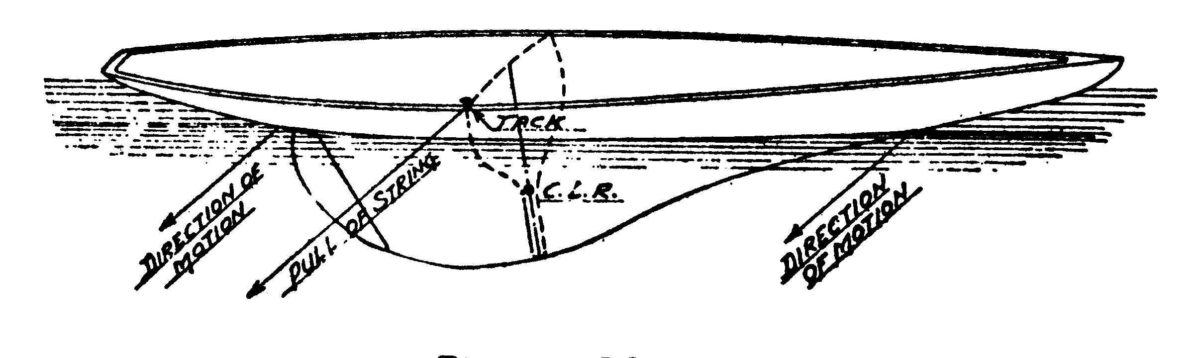
The calculation for the center of lateral resistance for our boat is given in the following:
|
|

The distance from Station No. 1 to Station No. 5 is 16.50, so that CLR (center of lateral resistance) is 1.82 inches aft of Station No. 5.
[A simpler method for finding the CLR is to use a piece of thick cardboard or thin ply in the shape of the underwater profile of the boat. Lay this horizontally on a knife edge vertical to the LWL, and slide it back and forth until it balances. That point of balance is the location of the CLR. —ED).
Now go back to the sail plan and draw in the hull definitely so that the CLR is slightly aft of the CE (center of effort). The amount of the horizontal distance between these two centers is determined by experience. Generally speaking, the distance should be greater on broad, full-bodied boats than on keen, sharp-lined craft. As our boat is distinctly in the latter category, it is believed that a “lead”-as it is called-of 1 1/4 inches of CE forward of CLR is about right. The general practice is to make this distance from 2 1/2 per cent to 5 per cent of the water-line length with an average say, of 4 percent.
We can show a spinnaker on our sail plan, which should be proportioned as follows:
The hoist of the spinnaker is the distance measured from the deck on the foreside of the mast where the line of the luff of the jib when extended cuts the mast. The base of the spinnaker shall be from the forward side of the mast to the bowsprit end or point where the forestay meets the deck.
We have now performed all the ordinary operations of designing a model sailing yacht, such as lie within the scope of this work. A great deal of additional work may be performed, such as investigating the balance of the hull when heeled and investigating the conditions of stability.