“Until You Get it Right, Part The Second”
In Which We Finally Get it Close Enough To Right To Move On
by Earl Boebert
A Note on Craftsmanship and Time
A model racing yacht is a hybrid beast in that it is at once a manifestation of your skill as a builder and also a piece of sporting equipment. This leads to some interesting tradeoffs with regard to the time you devote to your hobby/sport. Bluntly said, every hour spent constructing a work of art is an hour you are not spending on the water, tuning your boat and sharpening your skill. Some folks solve this problem very simply — they buy their boats, and spend all their time on the water. Others are on the other end of the spectrum — they build works of art, but don’t sail much. I’m someplace in the middle. I admire and aspire to the level of craftsmanship of the experts, but freely admit to “moving on” when I get something that is good enough. Hull 6 isn’t going to knock anybody’s socks off, but it’s about the right shape, plenty strong, and light. So it’s the one I campaigned in the free sailing regatta at San Francisco and the free sailing and R/C regatta at Marblehead. [Aug. 2001. It was light, all right, but not as strong as it could have been.]
Hull 6
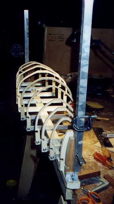
Aligning the frames for Hull 6. I went back to the plans and discovered that there was a pretty severe distortion based on the paper shrinkage (we’re working off of copies of copies of copies.) I redrew the sections and refaired the plans, and things went a lot better this time.
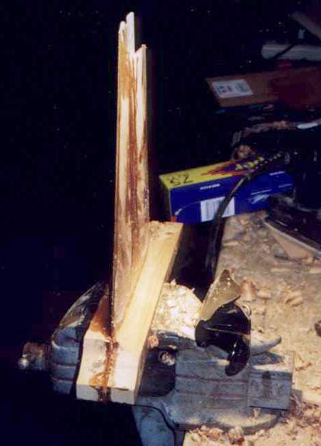
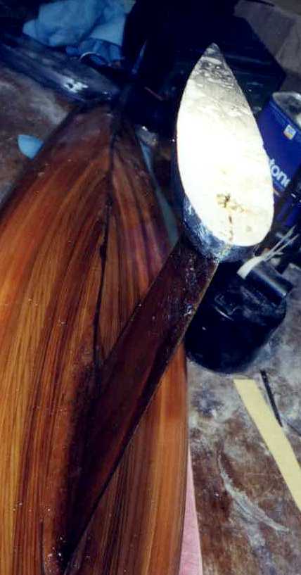
The fin, laminated as in Hull 5. The big difference is the solid mahogany fairings for where the fin joins the hull. The gizmo sitting on the vise is a Stanley 100 1/2 plane, designed by the great model yachtsman John Black for cutting such convex curves. [Aug. 2001: that block looks plenty solid, but when it’s carved away to form the garboard radius there just isn’t enough left to hold the fin to the hull.]
Laying the built-up rabbet, looking forward. I doubled the width of the underlying piece at the bow, which largely (but not completely) eliminated the problems I had with Hull 5 at that point. The one-piece fin plus fairing was aligned as with Hull 5.
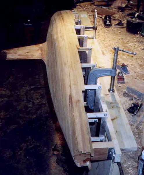
Fairing, with planes as before. One advantage of the narrow building board is that you can clamp it horizontally on the edge of the bench, as shown. This makes it much easier to see what you are doing.
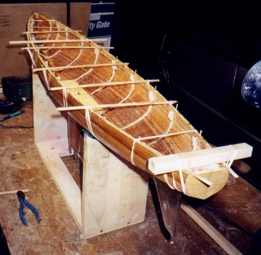
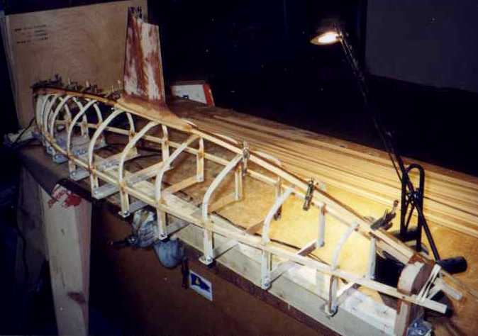
Laying the stopwater along the sheer. 1/4″ spruce, later planed down to deck level. Sheer line, skeg alignment, etc. as with Hull 5. This picture shows the horizontal planking method to good advantage. For this hull I started at the LWL and worked both ways. Very successful, except that “cheaters” were needed at the stern.
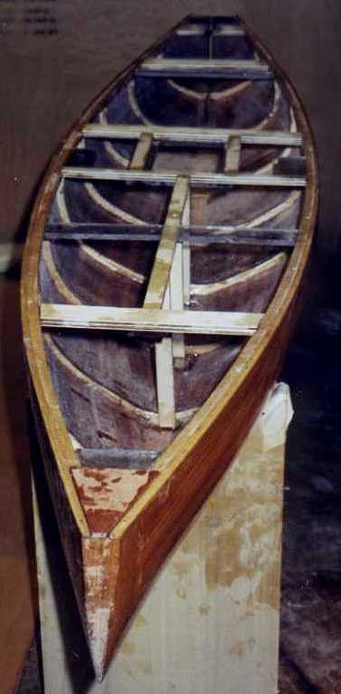
The interior bracing. Everywhere a stress fitting is placed on the deck, I put a 3/16″ Lexan (plastic) “hard point” underneath. The fittings are attached with #4 stainless self-tapping screws down into the Lexan. Besides being strong, this enables the fittings to be removed and replaced many times — a real advantage to someone like me, who seldom gets things right on first attempt.
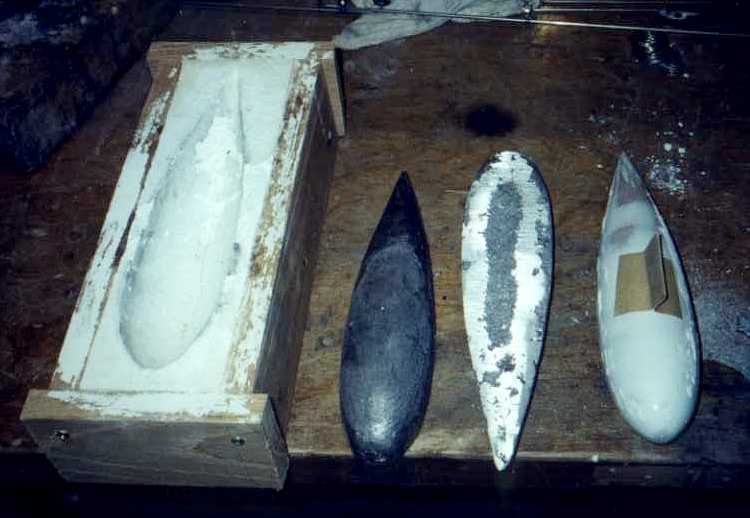
The bulb pattern on the right, the simple “puddle mold” made from Hydrocal (the stuff model railroaders use for scenery) on the left, and the two bulb halves in the middle. The bulb is split horizontally, not vertically, a technique developed by Bob Sterne. Makes for easier alignment and a much stronger fixture.
The bulb is attached last, so you don’t have to heave all that weight around when you’re doing stuff on the hull. The aft stainless strip has a 1/8″ diameter hole drilled in it just above the horizontal centerline of the bulb. The top half of the bulb is slit to accept the two stainless strips in the fin, and a slot routed in it where the hole is. A 1/8″ stainless safety rod is slipped transversly into the slot and through the hole. The whole thing is checked for alignment and potted together with epoxy. Then the bottom half is epoxied on, with a #6 stainless self-tapping screw for safety. The resultant assembly could be used to kill a horse without the bulb coming off the fin. [Aug. 2001: Right, but as I learned, the fin can come off the boat!]
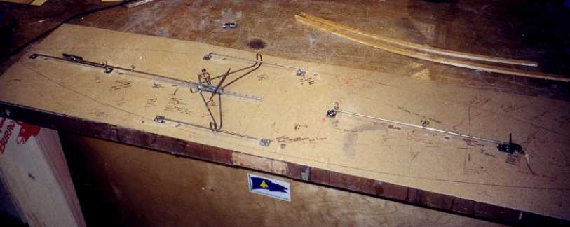
“Iron Bird” test fixture for the rig. The boat is designed to sail either under vane or radio. The rig can be slid over a 7″ range to place the mast in optimal position for the conditions of the day. Since free sail rigs are pretty simple, this poses no particular problem. I wanted to be able to slide the rig under radio, so I could tune the boat that way. This is much more complicated, hence all the scribbling on the baseboard.
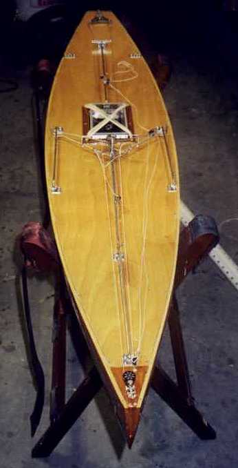
Decked and with the running rigging in place. The final weights: hull with deck and bracing, 2 lbs even. Fin, 10 oz. (counts toward ballast). Rig, 1 lb. 6 oz. Lead, 14 1/2 lbs. The modern version carries 1 lb. more lead than the 1949 original.
The running rigging shown here was not a success. What I neglected to take into account was the fact that a free sailing boat sails almost all the time with the running rigging taut — you don’t start until the wind fills your sails. A R/C boat has slack lines laying on the deck all the time. There are a bunch of fittings required for free sailing that just love to catch and foul slack rigging. Back to the drawing boards. The solution seems to work, but I’m not describing anything until I’m sure.
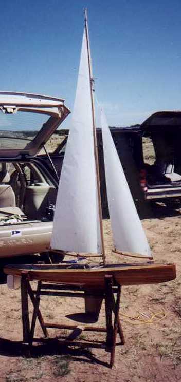
Rigged and ready to launch, at the undisclosed New Mexico test site. The car gives an idea of the size of an M boat. Butterflies …. naaah ….. well, maybe.
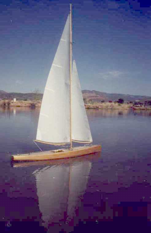
Ghosting along on the sigh of relief I emitted when it turned out she trimmed out just about exactly on the design waterline … just kidding. Seriously, with the fixed ballast, an out of trim boat takes major surgery, and we would be on the way to Hull 7. Now, if the Mark II running rigging works, I just intend to sail her, and sail her, and …. you get the picture.
Click Here to see how things went at San Francisco and Marblehead, and here if you want to go directly to the saga of Hull 7.