Computer Radio Use in R/C Yachting
by Gudmund Thompson
My foray into radio-controlled sailboats began only a couple of years ago, but my background includes a good deal of experience in designing, building, and flying radio-controlled sailplanes, where a model can reasonably be expected to have 12–18 servos and computer radios are the norm. I even managed to produce an effective stall sensor, based on an Arduino microcomputer and a pair of sensors, that used my transmitter’s sound and haptic capabilities to warn of impending disasters. As a result, I have both the radio equipment and the skill to experiment with elegant and sometimes needlessly complicated sail management systems.
Purpose
The objective of this article is to explore the capabilities of a modern computer-based radio using several increasingly complicated scenarios. I will start simple, and hopefully show how a series of relatively straightforward mixes can be combined into a functional, elegant, and reliable boat-management system. I will not provide a “how-to” that will be applicable to all radio systems, but hopefully the fundamentals that I describe will put you in a position where—with the help of an appropriate operating manual—you can use an appropriate computer radio1On the question of which computer radios cannot do what this article will describe and which can, I think that the dividing line is between radios that follow the unchangeable airplane-centric Throttle–Aileron–Elevator–Rudder-style channel assignment and the radios that allow any channel to host any function. The former, provided they have a mixing capability, can certainly do the things I will refer to, but getting them to do it all would be a bit of a struggle. With the latter group, however, the challenge is simply a matter of figuring out “how” to do it. to control your own sailboat’s functions.
General Information
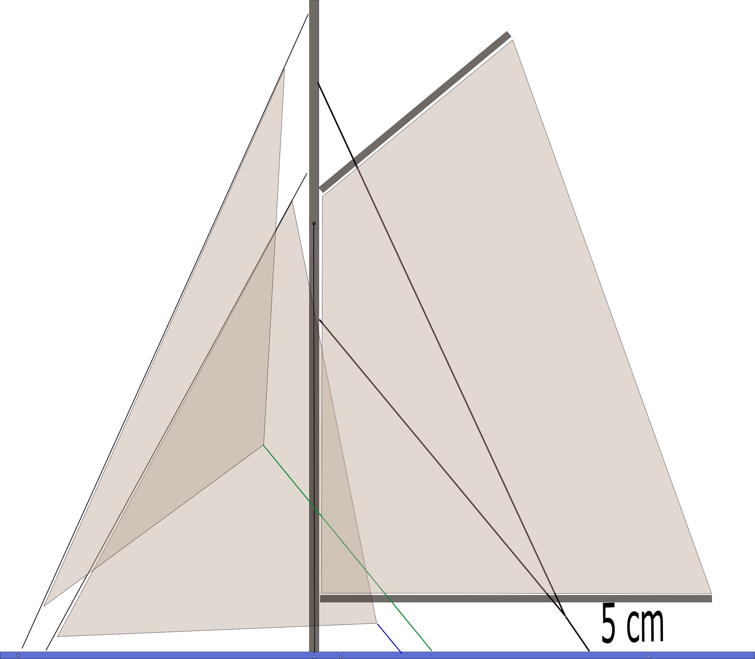
There are a bewildering number of terms that manufacturers use to describe how to use their radios. To avoid confusion, I am going to be consistent with the use of the following terms:
- sail management assembly – the servo-based group of components that interprets the signals from the radio and produces the actions needed to control the sails;
- range (of movement) – the distance that each component of the rig (rudder, sheet, running backstay, etc.) needs to move to control the sailboat;
- throw – the distance that a servo can move a line or rod using a servo horn (arm) or drum;
- input – a stick, lever, button, slider, etc. located on the transmitter, and may even include an audio input (shouting) or a physical manipulation of the radio (such as rotating it though one of its axes or shaking it!);
- control – this is also a stick, lever, button, slider, audio, or shaking, etc. that is used to modify an input;
- virtual switch – when two or more sticks, levers, buttons, sliders, audio, or shaking, etc. are used in combination to produce an input or control;
- mix – when a control is used to modify an input, the mix identifies the input, the control, and the percentage of the throw needed to achieve range required; and
- output – the receiver channel that is associated with the servo in the model.
The temptation to use audio or transmitter shaking inputs is strong, but my preference is to use only:
- the left–right axis of the transmitter’s right stick as the rudder input;
- the up–down axis of the left stick as the sheets input;
- the left–right axis of the left stick as the jib trim input;
- the forward and back movement of a two-position switch located at the top right of the transmitter to select between high- and low-rate control for the rudder;
- the forward and back movement of a two-position switch located at the top left of the transmitter to select between the port and starboard tack control;
- the downward movement of the rudder stick to select the safe jibing control; and
- the up-down movement of a two-position switch in the lower center of the transmitter to select between the setup control and the normal sailing mode.
Scenario 1
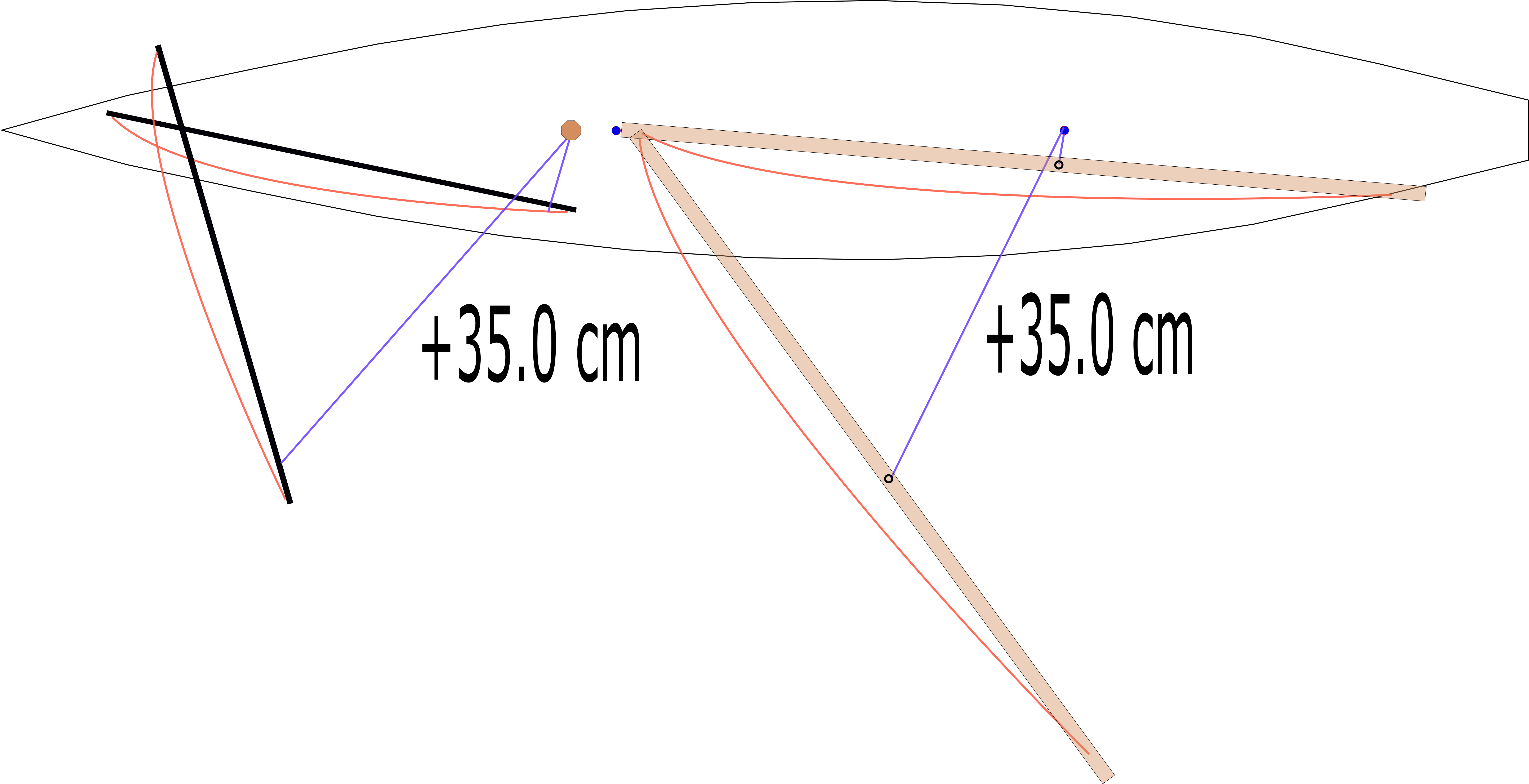
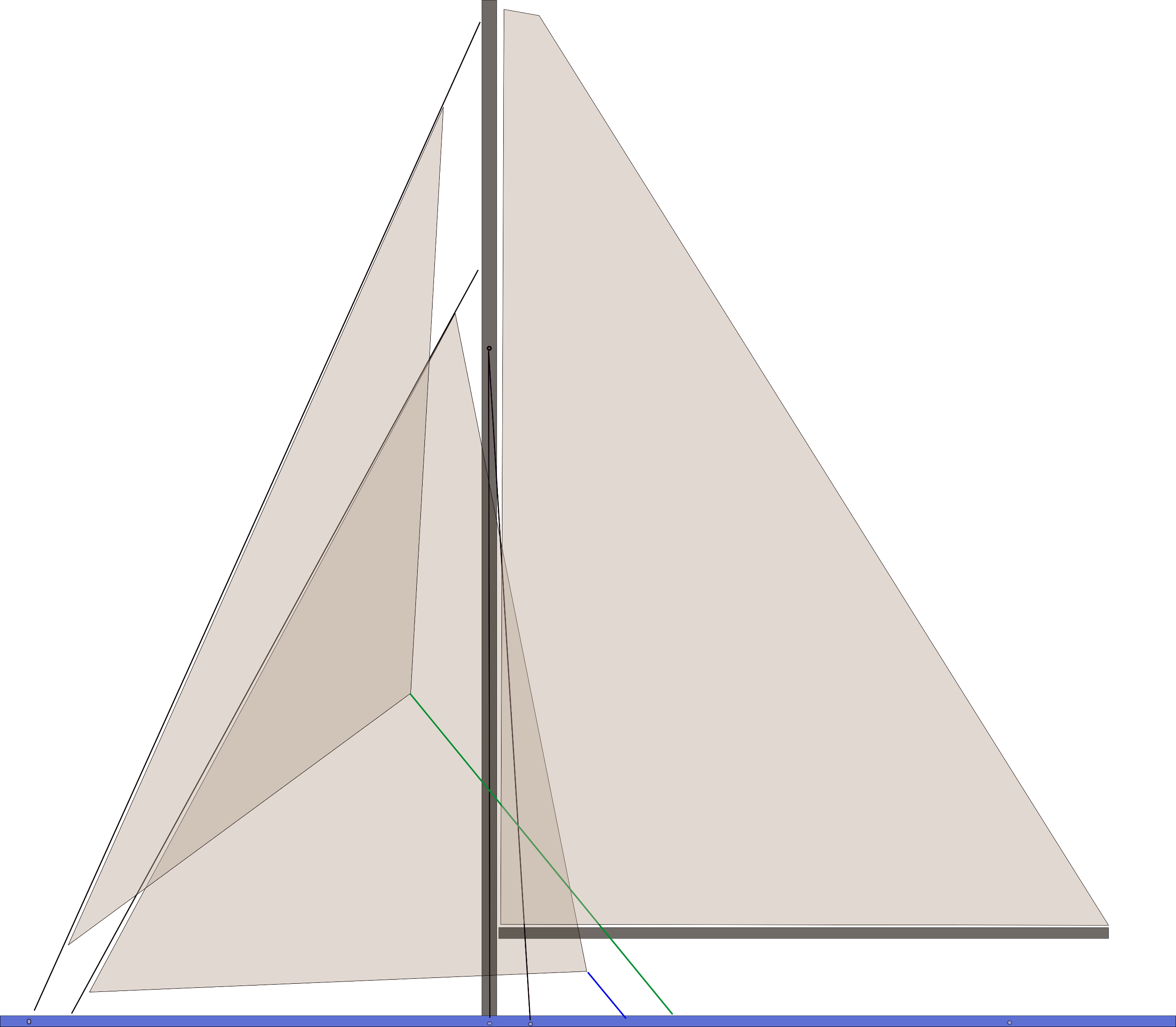
On this sloop, both the main and jib sheets need 35 cm of sheet travel to move the sails from close-hauled to running.
Let me start with something simple: a sloop, whose sail management system consists of a single winch servo controlling two sheets, the jib and main; a second servo to trim the jib; and a rudder servo. Experimentation and calculation have determined that for this model to sail correctly:
- the rudder servo will need to rotate through 45% of its maximum throw to provide the range of movement needed to move the rudder through the arc required;
-
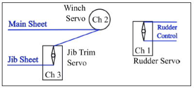
Here are the three servos. The winch servo controls both the main sheet and the jib sheet, but the latter can be adjusted by the jib trim servo.
the winch servo will need to rotate through 70% of its throw to provide the 35 cm of sheet movement needed to adjust the main and jib sails from close-hauled to running; and
- the jib trim servo will need to rotate through 100% of its throw to provide the needed jib sheet adjustment.

With this data, we can then program the radio by:
- identifying the inputs:
- the left–right axis of the right stick is the rudder input (rudder stick),
- the up–down axis of the left stick is the main and jib sail input (sail stick), and
- the left–right axis of the left stick is the jib trim input (jib trim stick);
- setting the throws (because there is no mixing involved, this can be done in the transmitter’s servo setup menu):
- the rudder throw is -45% to +45%,2Limiting the throw of the rudder servo to 45% of its maximum is achieved by using 45% of the servo’s negative capability and 45% of its positive capability.
- the sail throw is -70% to +70%, and
- the jib trim throw is -100% to +100%; and
- assigning the outputs:
- the rudder output is channel 1,
- the sail output is channel 2, and
- the jib trim output is channel 3.
Here is a nice little table showing what we have done.
| Servo | Input | Throw | Output |
|---|---|---|---|
| Rudder | Rudder Stick | -45% to +45% | Channel 1 |
| Sail | Sail Stick | -70% to +70% | Channel 2 |
| Jib Trim | Jib Trim Stick | -100% to +100% | Channel 3 |
However, many sailors like to have dual rates on their rudder to reduce its sensitivity while going downwind in a strong breeze. This is easy to achieve by adding two mixes, but first, you will need to go back to the servo setup menu and reset the throw of the rudder servo to -100% to +100%.3If you do not reset the rudder output in the servo setup menu, the mixes created below will only result in 30% and 45% of 45% of the servo’s maximum throw.
With the left-right axis of the right stick set as the rudder input (rudder stick), create two mixes4There are many ways of achieving the goal here, and the one I am going to demonstrate is probably the most complicated. It assumes that the transmitter being used needs to have both sides of the two-position switch defined in order to work properly. The result will be an either/or situation where only one of the values (high rate or low rate) is possible. In other circumstances, we will want the control to adjust an input, not replace it.:
Mix 1
- identify the away position of the two-position switch at the top right of the transmitter as the high range control (high range switch);
- set the throw at -45% to +45%; and
- assign the output to channel 1.
Mix 2
- identify the toward position of the two-position switch at the top right of the transmitter as the low range control (low range switch);
- set the throw at -30% to +30%; and
- assign the output to channel 1.
Now the table looks like this.
| Servo | Input | Control | Throw | Output |
|---|---|---|---|---|
| Rudder | Rudder Stick | High Range Switch | -45% to +45% | Channel 1 |
| Low Range Switch | -30% to +30% | |||
| Sail | Sail Stick | -70% to +70% | Channel 2 | |
| Jib Trim | Jib Trim Stick | -100% to +100% | Channel 3 |
Scenario 2
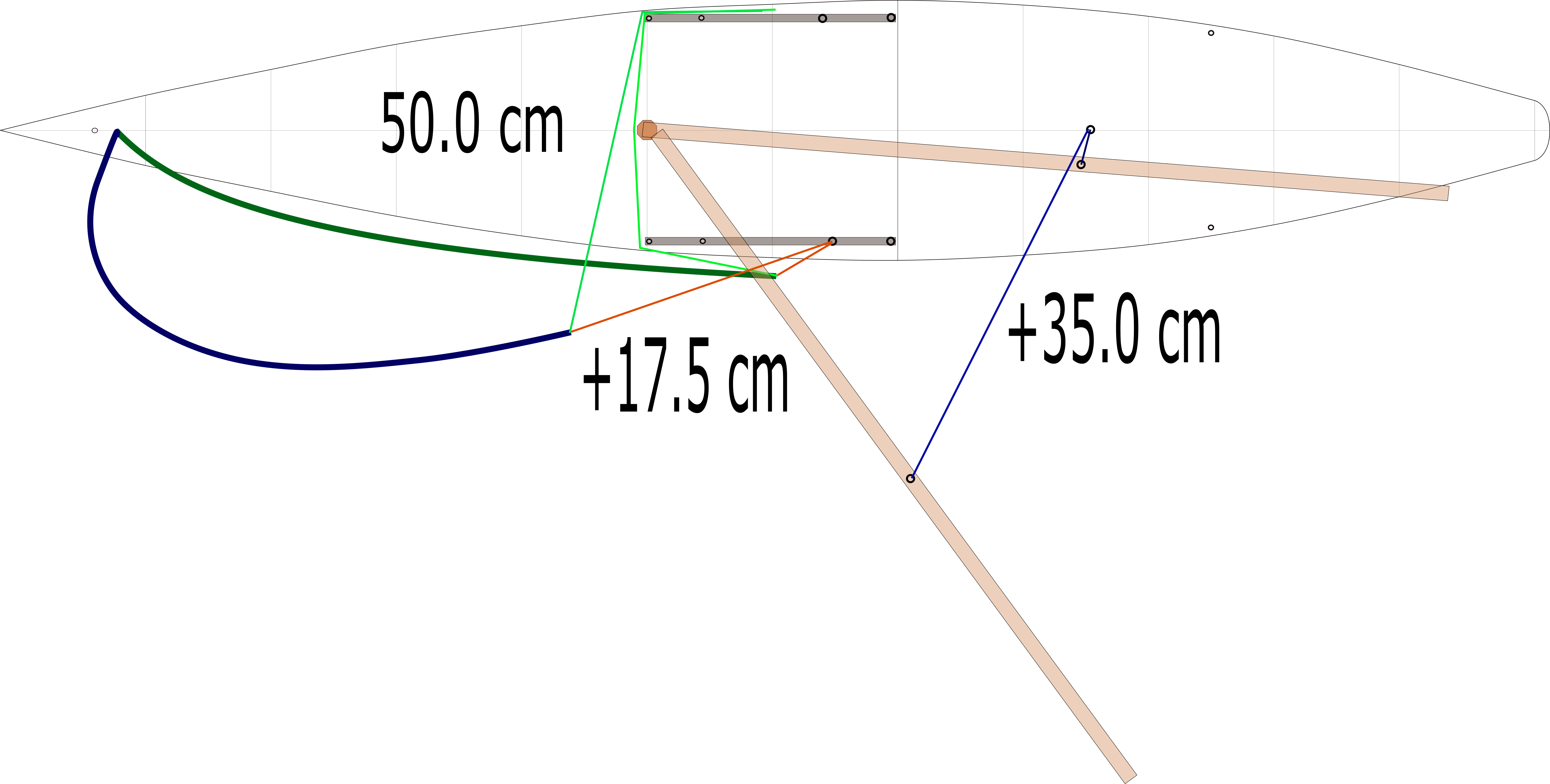
With this sloop, when on starboard tack, the genoa sheet on the port side (the red line) needs 17.5 cm of travel to go from close-hauled to running. The starboard sheet (the green line), however, can remain stationary throughout the starboard tack maneuvering.
To shift from port tack to starboard tack, the sheets both need to travel 50 cm to get to close-hauled on the new tack.
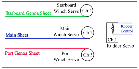
What if we get a little more adventurous and look at a sloop-rigged boat that has a genoa as a headsail. In this case, we will use three sail winch servos: one for the main sheet and two for the genoa – one on the port side and the other on starboard. While we still want to trim the genoa, we do not need a jib trim servo to do so, and we will want to keep the rudder servo.
For this boat, experimentation and calculation has determined that:
- on high-rate, the rudder servo will need to rotate through 45% of its throw to provide the movement needed to move the rudder through the arc required, on low-rate, 30%;
- the winch servo controlling the main will need to rotate through 70% of its throw to provide the 35 cm of sheet movement needed to move the sail from close-hauled to running;
 the winch servo controlling the genoa on the port side will need to rotate through:
- 35% of its throw to provide the 17.5 cm of sheet movement needed to move the sail from close-hauled to running while it is on starboard tack,
- 0% of its throw to provide the sheet movement needed to move the sail from close-hauled to running while it is on port tack, and
- 100% of its throw to move from close-hauled on starboard tack to close-hauled on port tack, or vice-versa;
- the winch servo controlling the genoa on the starboard side will need to rotate through:
- 35% of its throw to provide the 17.5 cm of sheet movement needed to move the sail from close-hauled to running while it is on port tack,
- 0% of its throw to provide the sheet movement needed to move the sail from close-hauled to running while it is on starboard tack, and
- 100% of its throw to move from close-hauled on port tack to close-hauled on starboard tack, or vice-versa; and
- both the starboard and port genoa servo will need to rotate through 5% of its throw to provide the genoa sheet adjustment needed to trim the jib.
We can then program the radio as follows.
Rudder – use mix 1 and 2 from Scenario 1.
Mainsail – use the setup from Scenario 1
Port-side genoa
- with the up–down axis of the left-hand stick set as the genoa sail input (sail stick), create two mixes5As was the case with the dual rate mixes, only mix 3 or mix 4 can be active at any given time.
- Mix 3
- identify the away position of the two-position switch at the top left of the transmitter as the port tack control (port tack switch);
- set the range as +100% to +100%6While the sail stick can be at any point on its axis, mix 3 restricts the port-side genoa servo’s range to 0 cm (+100% to +100%).; and
- assign the output to channel 3.
- Mix 4
- identify the toward position of the two-position switch at the top left of the transmitter as the starboard tack control (starboard tack switch);
- set the range as -100% to -30%7 -100% to -30% is 35% of the servo’s range, which provides 17.5 cm of sheet movement.; and
- assign the output to channel 3.
- Mix 3
- with the left–right axis of the left stick set as the genoa trim input (genoa trim stick), create the following mix,
- Mix 5
- identify the toward position of the two-position switch at the top left of the transmitter as the starboard tack control control (starboard tack switch);
- Set the range as -5% to +5%; and
- Assign the output to channel 3.8Unlike mix 3 and 4, which replace each other, here you want the mix to modify, not replace. Depending on the transmitter, you may need to identify this mix as an “addition to mix 4.” You want the +5% to -5% jib trim to modify the -100% to -30% positioning established by the sail control after it has been positioned by the port-starboard control.
- Mix 5
Starboard-side genoa9My assumption is that the two jib servos are sitting in the same orientation but turn in opposite directions in response to changes in the sail input. The port genoa servo, when close-hauled on starboard tack, is at -100%, while the starboard genoa servo, when close-hauled on port tack, is at +100%.
- with the up–down axis of the left-hand stick set as the genoa input (sail stick), create two mixes,
- Mix 6
- identify the toward position of the two-position switch at the top left of the transmitter as the starboard tack control (starboard tack switch);
- set the range as -100% to -100%; and
- assign the output to channel 4.
- Mix 7
- identify the away position of the two-position switch at the top left of the transmitter as the port tack control (port tack switch);
- set the range as +100% to +30%; and
- assign the output to channel 4.
- Mix 6
- with the left–right axis of the left stick set as the genoa trim input (genoa trim stick), create the following mix,
The table should look like this.
| Servo | Input | Control | Throw | Output |
|---|---|---|---|---|
| Rudder | Rudder Stick | High Range Switch | -45% go +45% | Channel 1 |
| Low Range Switch | -30% to +30% | |||
| Main Sail | Sail Stick | -70% to +70% | Channel 2 | |
| Port-Side Genoa | Sail Stick | Port Tack Switch | +100% to +100% | Channel 3 |
| Starboard Tack Switch | -100% to -30% | |||
| Genoa Trim Stick | Starboard Tack Switch | -5% to +5% | ||
| Starboard-Side Genoa | Sail Stick | Starboard Tack Switch | -100% to -100% | Channel 4 |
| Port Tack Switch | +100% to +30% | |||
| Genoa Trim Stick | Port Tack Switch | +5% to -5% |
Imagine, you are cruising along, close-hauled, on a port tack (the port-starboard switch is in the port position, the sail stick is at the bottom of its run, and the rudder is in the center of its run). Suddenly (actually, it should never be suddenly, but a little drama cannot hurt here), you notice a boat on starboard tack approaching on a collision course. Cool as a cucumber, you use the rudder to initiate a turn into the wind, and as the bow of the boat passes through the wind, you flip the port-starboard switch to starboard. If your timing is just right, the genoa will be pulled into the starboard tack, close-hauled position by the genoa servos, the mainsail will be pushed onto starboard tack by the breeze, both sails will fill, and you will sail away out of danger. Is not sailing fun!!
Scenario 3
On this boat, the foremost headsail has more overlap than does the rearmost, and consequently will need more sheet travel.
What if we put two foresails on the boat, both overlapping? What then? Again, we can use three sail servos, one for the main sheet, and two for the headsails, but this time each headsail servo will drive two sheets – one for each of the foresails. If we are clever and design the rigging so that the two headsails can be managed with the same amount of sheet throw, we will not need trim servos. But, as is often the case, if the two headsails have different sheet travel requirements, we will need to add a trim servo to each side as well. Of course, we will need to keep the rudder servo.
Let us say our calculations determine that the foremost headsail requires more sheet travel than does the rearmost, and that this difference can be made up by using 80% of the travel that we got from the jib trim servo setup in Scenario 1.
 With this in mind, we run the sheets for the foremost headsail through the headsail trim servos and the sheets for the rearmost foresail directly from the servos. This will shorten the port sheet of the foremost foresail when the sails are on port tack (while lengthening the starboard sheet) and shorten the starboard sheet of the foremost foresail when the sails are on starboard tack (while lengthening the port sheet).
As this boat is essentially the same as the one in Scenario 2, the table looks like this.
| Servo | Input | Control | Throw | Output |
|---|---|---|---|---|
| Rudder | Rudder Stick | High Range Switch | -45% go +45% | Channel 1 |
| Low Range Switch | -30% to +30% | |||
| Main Sail | Sail Stick | -70% to +70% | Channel 2 | |
| Port-Side Genoa | Sail Stick | Port Tack Switch | +100% to +100% | Channel 3 |
| Starboard Tack Switch | -100% to -30% | |||
| Genoa Trim Stick | Starboard Tack Switch | -5% to +5% | ||
| Starboard-Side Genoa | Sail Stick | Starboard Tack Switch | -100% to -100% | Channel 4 |
| Port Tack Switch | +100% to +30% | |||
| Genoa Trim Stick | Port Tack Switch | +5% to -5% | ||
| Port-Side Headsail Trim | Sail Stick | Port Tack Switch | -80% to -80%. | Channel 5 |
| Starboard Tack Switch | +80% to +80%. | |||
| Starboard-Side Headsail Trim | Port Tack Switch | +80% to +80%. | Channel 6 | |
| Starboard Tack Switch | -80% to -80%. |
Scenario 4
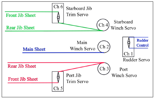
The running backstay on the leeward side of the boat needs to have 5 cm of slack when close-hauled,
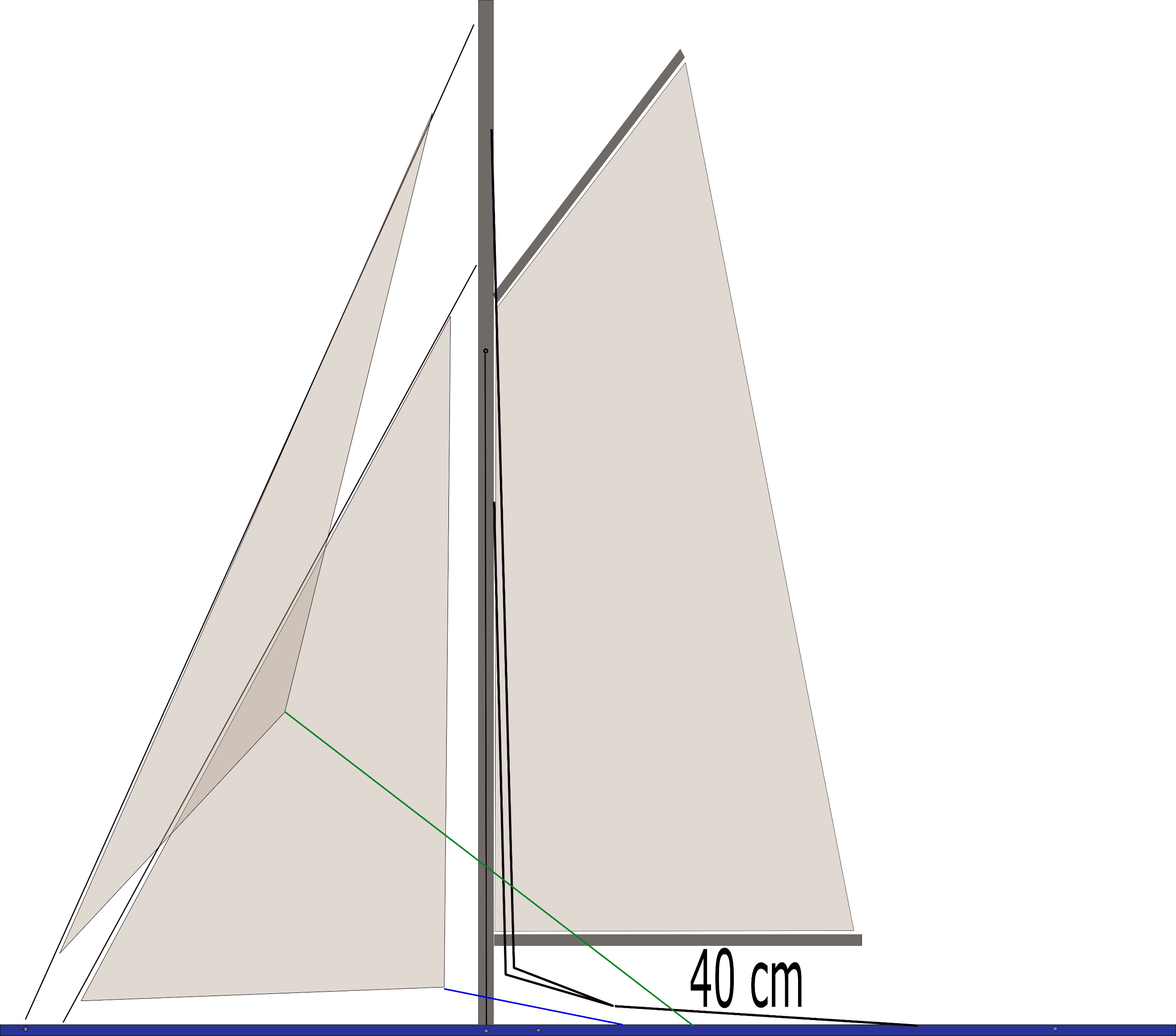
and needs to be loosened a further 35 cm to keep it from interfering with the mainsail when running.
What if we were interested in adding the controls for a pair of running backstay to this boat?
Running backstays replace the backstay on some boats and are required because the boom is longer than the distance from the mast to the back of the boat, leaving no place to attach the backstay without interfering with the boom’s travel when tacking or jibing. Generally only one of the runners is tight at any given time. On a starboard tack, with the boom on the port side of the boat, the starboard runner should be tight while the port one should be loose enough that it does not interfere with the set of the mainsail. The opposite is true on the port tack. The fun part of runners is getting them to swap tightness at the right time.
Let us say our calculations and experiments determine that the runner control line needs to move 40 cm to go from the tight and locked position to the completely loose position, and let us assume that servo setup that we are envisaging can produce this amount of throw.11Unlike with the port and starboard genoa servos – which I assumed were both upright and turning the same direction – it is more reasonable to assume that the running backstay servos are mounted facing each other. Also, our experiments suggest that the on starboard tack, the port runner needs to start with 5 cm of slack to clear the boom at close-hauled.
Using the input from the Sail stick in conjunction with the Port and Starboard Tack controls to coordinate the running backstays, the chart now looks like this:
| Servo | Input | Control | Throw | Output |
|---|---|---|---|---|
| Rudder | Rudder Stick | High Range Switch | -45% to +45% | Channel 1 |
| Low Range Switch | -30% to +30% | |||
| Main Sail | Sail Stick | -70% to +70% | Channel 2 | |
| Port-Side Genoa | Sail Stick | Port Tack Switch | +100% to +100% | Channel 3 |
| Starboard Tack Switch | -100% to -30% | |||
| Genoa Trim Stick | Starboard Tack Switch | -5% to +5% | ||
| Starboard-Side Genoa | Sail Stick | Starboard Tack Switch | -100% to -100% | Channel 4 |
| Port Tack Switch | +100% to +30% | |||
| Genoa Trim Stick | Port Tack Switch | +5% to -5% | ||
| Port-Side Headsail Trim | Sail Stick | Port Tack Switch | -80% to -80%. | Channel 5 |
| Starboard Tack Switch | +80% to +80%. | |||
| Starboard-Side Headsail Trim | Port Tack Switch | +80% to +80%. | Channel 6 | |
| Starboard Tack Switch | -80% to -80%. | |||
| Port-Side Runner | Sail Stick | Port Tack Switch | -100% to -100%. | Channel 7 |
| Starboard Tack Switch | -75% to +100%. | |||
| Starboard-Side Runner | Port Tack Switch | +75% to -100%. | Channel 8 | |
| Starboard Tack Switch | +100% to +100%. |
Close-hauled tacking from port to starboard is achieved by using the rudder to maneuver the boat through the wind and flipping the port–starboard switch to change tacks. If this is done correctly, and without moving the sail stick, the starboard foresail sheets slacken while the port-side sheets tighten, the wind pushes the main boom across the boat, and the port-side runner loosens while the starboard-side runner tightens. If all of this happens in a timely manner, the boat will fall off onto roughly the same point of sail, but on the opposite tack.

The servo on the left is in the overlocked and tight position while the one on the right may require unacceptable current draws to remain in this position.
If the close-hauled tack takes place on the far side of the pond because of a wind shift while the boat is being obscured by another boat, the fact that you have not flipped the port-starboard switch in a timely manner is not going to be catastrophic. The foresails will be leaning against the forestay and mast, and the mainsail will be resting on the tight runner. Flipping the port-starboard switch at this point will likely get things sorted out without a lot of drama—though it may be ugly —as the loose runner does not have far to go to get into the overlocked12The overlocked position of the backstay servo essentially reduces the amperage draw of the servo to zero, while providing a pull whose strength is dependent of the physical capabilities of the line, the mechanical construction of the servo, and physical strength of the mounting structure. Essentially, the runner using this setup should stay tight until the line breaks, or the servo breaks, or it is wrenched out of its mount. and tight position.
Unfortunately, an unintended jibe—or even just a poorly executed one—could result in significant drama. Here, it is possible for the tensioned runner to be released before the needs-to-be tensioned runner is firmly in the overlock and tight position. The consequence could be a stalled servo (using lots of electricity) and a very poorly supported mast. Almost certainly not an ideal situation.
My solution has been to program my radio such that a safe jibing mix can include an instant—or longer—when the main boom is being held tightly at the center-of-boat-position by the mainsail sheet. This means that the mainsheet will support the mast while the runners are swapping positions—the boom needs to pass through this position during any jibing maneuver anyway, so this is just a matter of timing.
To program this I needed to establish a “safe jibe control,” and ensure that the mix assigned to it supersedes any other mixes that may cause problems. This can be done in a few ways, the easiest of which is to replace the two-position port–starboard switch with a three-position one. If the away and toward positions of the three-position switch are identified as the port and starboard controls, the center position can be the safe jibe control. In this setup, there can only be one of the three controls active at any given time, and any potential mix issues are eliminated. But I do not like this approach. Maybe it is just not elegant enough?
My preference is to use the up–down axis of the right-hand stick to provide the safe jibe control, leaving the port–starboard controls on a two-position switch.
- the safe jibe control will be activated when the right-hand stick is lowered until it is within the bottom third of its run;
To eliminate any issues, I will use “virtual switches” to define the port, and starboard controls as follows:
- the starboard tack virtual switch control will be activated when the top left two-position switch is in the toward position, AND the right-hand stick is NOT in the safe jibe position; and
- the port tack virtual switch control will be activated when the top left two-position switch is in the away position, AND the right-hand stick is NOT in the safe jibe position.
With the safe jibe control established, I can create mixes in which I set the range for the main sail at +75% to +75% and the ranges for the two runners at -100% to -100% and +100% to +100% respectively.
The mainsail and runner portions of the table would look like this:
| Servo | Input | Control | Throw | Output |
|---|---|---|---|---|
| Main Sail | Sail Stick | -70% to +70% | Channel 2 | |
| Safe Jibe Switch | +75% to +75% | |||
| Port-Side Runner | Sail Stick | Port Tack V-Switch | -100% to -100%. | Channel 7 |
| Stbd Tack V-Switch | -75% to +100%. | |||
| Safe Jibe Switch | -100% to -100% | |||
| Starboard-Side Runner | Sail Stick | Port Tack V-Switch | +75% to -100%. | Channel 8 |
| Stbd Tack V-Switch | +100% to +100%. | |||
| Safe Jibe Switch | +100% to +100% |
This jibing process only uses the two axes of the right-hand stick. The left–right axis activates the rudder and turns the boat out of the wind, while moving the stick to the lower third of the up–down axis both pulls the main boom to the center of the boat and tightens both runners. Then, with the boat passing through the wind, the port–starboard switch is flipped, and the safe jibe stick is returned to the center position allowing the sails to fill on their proper sides and the appropriate runner to loosen. When done correctly, the boat falls off onto roughly the same point of sail, but on the opposite tack, and the maneuver is very smooth with little drama. I should point out that in moderate to heavy winds, the process depends greatly on a very powerful mainsail servo.
With these mixes added to the programming, whenever the positioning of the runners is in doubt, safe jibe control can be activated and held until things are sorted out.
Scenario 5
The final issue I want to cover is the programming that I use during the assembly and setup of my Nottingham.
At 60 inches in length, the possibility of leaving the boat rigged between sailing sessions is nonexistent. Furthermore, attempting to rig the boat without power means that runner servos are either in the overlocked position—making the runner attachments impossible, or free to move—where no support for the mast is provided. This, and other inconveniences, caused me to create a “setup.”
To do this, I identified the away position of the switch in the lower center of the transmitter as setup control, and, when it is selected, the mixing causes:
- the mainsail servo to go to the close reach position—allowing easy attachment of the main sheet to the boom;
- the runner servos to both go to a slightly loose position—allowing the runner’s lines to be connected to the mast, but with enough tension to loosely support the mast;
- the foresail servos to go to a center position (halfway between port and starboard tacks) —allowing easy connection of the foresheets to clew of the sails; and
- the foresail trim servos to go to a center position—this does not accomplish much, but feels good.
The rudder servo is left to obey the input from the rudder stick.
When assembly is complete and I move the switch in the lower center of the transmitter to the toward position—essentially deselecting the setup control—the servos all move to whatever positions are being commanded by their inputs and controls, and I can go sailing.
Conclusion
If I have made your head ache and your nose bleed, I am sorry.
But, if I have prompted you to give a computer radio a try, I hope you can enjoy the experience.
I would, however, be remiss if I did not make note that I have only touched the surface of what a computer radio can do, especially when you add the capabilities of sensors and telemetry.