Article by TMY Editorial Staff. Photos by John Stoudt.
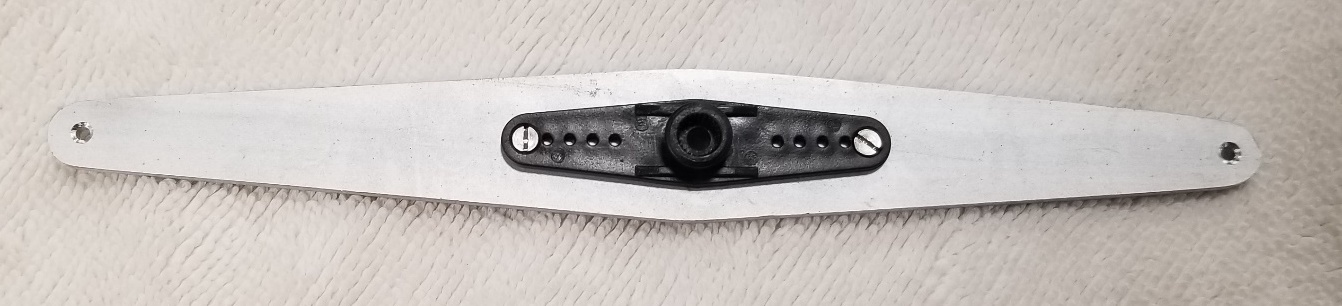
This is an efficient, strong sail control arm for R/C sailboats. It is an assembly of an aluminum arm and a servo horn that comes with the servo you intend to use as your sail control servo. There are many usable servos available today. Make sure the one you select to use has sufficient torque for the size of the boat.
Tools
- Band saw (metal cutting)
- Ruler
- Electric drill: hand drill or drill press
- 1-in band sander or metal cutting file
- Drill bits: 5/64-in, 3/32-in, and 3/8-in
- Countersink
- Center punch
- Circle template
- Sanding board, foam sanding block, and Scotch Brite sanding pad
Materials
- 1/8-in aluminum bar stock long enough for your sail arm. The width depends on the width of your sail control arm.
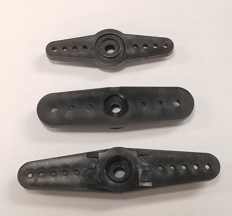
- Double-sided servo horn (comes with the servo. See Photo 1)
- The shaft diameter and the spline count are different on every manufacturer’s servos so make sure you choose the correct servo horn.
- Two 2-56 ½-in stainless steel flat head machine screws
- Two 2-56 stainless steel nuts
You must first calculate the length of your sail arm. See John Henderson’s article Setting Up Swing-Arm Sail
Controls that can be found at: https://usvmyg.org/setting-up-swing-arm-sail-controls/.
Making the sail control arm
- Cut a piece of aluminum about one inch longer than the lengths you have calculated using John’s article.
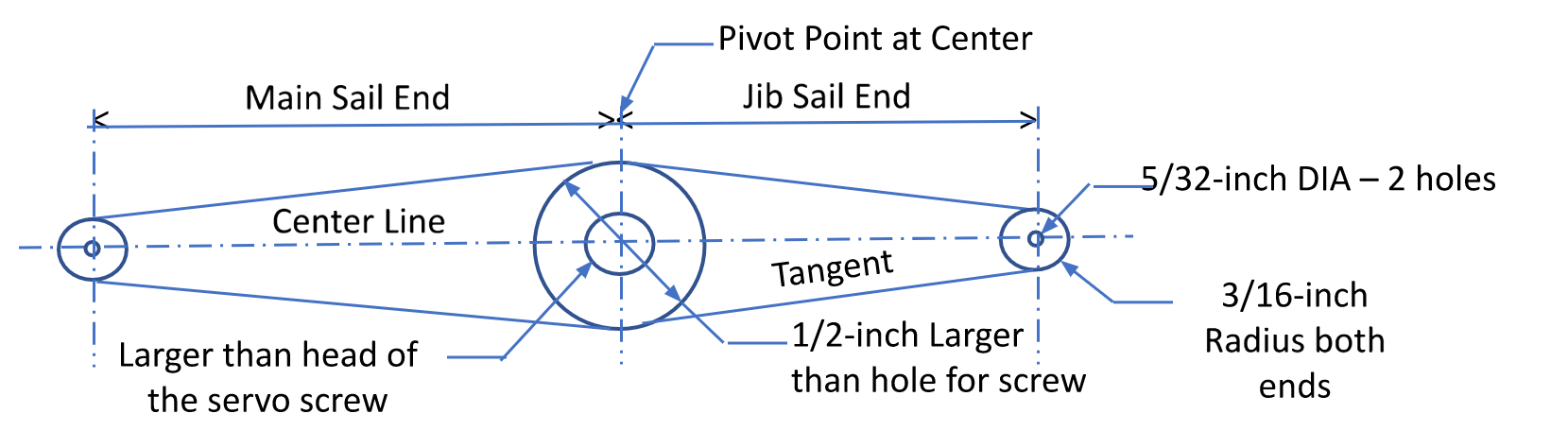
- Lay out the arm similar to the one in the illustration using the arm lengths you calculated and the servo screw head diameter.
- Begin the layout by drawing the centerline.
- Mark the location of the pivot point with a center punch (servo shaft center). This will be somewhere near the center of the arm on the centerline.
- Measure out in each direction for the mainsail arm side and the jib arm side.
- Mark each of those locations with a center punch.
- Using a circle template, draw a 3/8-in diameter circle at each end with the center point as the center of the circle.
- Measure the diameter of the head of the servo screw that holds the horn unto the servo. (If the screw head diameter is ¼ in, then the hole should be ⅜ in to allow 1/16 in of clearance around the screw head.)
- Using a circle template, draw a circle ½ in larger than the hole necessary for the servo screw to clear the hole. (If the servo screw hole is ⅜ in, then draw the circle ⅞ inch in diameter.)
- Draw tangents (four) with a straight edge from the outside edges of the small circles to the outside edges of the large inner circle.
- You now have your sail control arm ready to cut out.
- Carefully cut it out on a band saw just outside of the perimeter lines.
- Using a 1-in band sander or file, sand the edges straight.
- Sand the long edges on a sanding board to get them smooth and straight.
- Smooth the edges and round the corners with a foam sanding block.
- Drill a 5/32-in hole in each end of the arm.
- Put a very slight chamfer on these holes using a small countersink or drill bit. This helps to reduce fraying of the sheet lines.
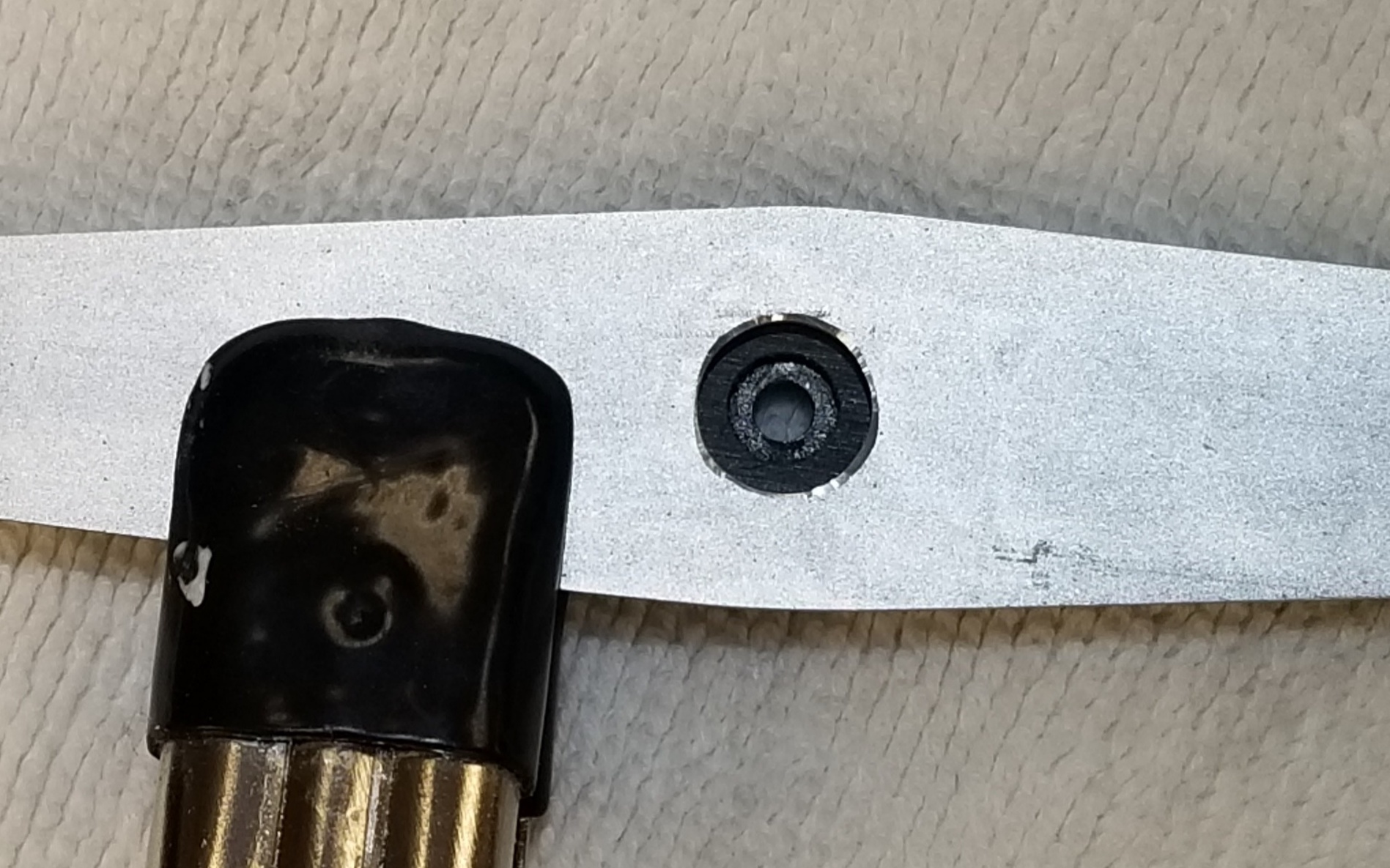
- Drill the servo screw hole that you determined in Step 8 in the pivot location. Debur the edges of the hole with a larger drill bit.
- Now clamp the servo horn in place over the large hole so the servo horn aligns with the centerline of the sail control arm. Make sure that the two holes are concentric. (See Photo 2).
- Drill a 3/32-inch hole at each end hole of the servo horn through the aluminum arm.
- Debur these holes.
- Countersink the bottom side of each drilled hole on the servo horn to receive the head of the 2-56 machine screw.
- Clean up the faces of the arm using the Scotch Brite pad.
- Bolt the servo horn to the aluminum arm by passing the 2-56 x ½-inch machine screws up from the bottom and attaching the nuts from the top. If there is too much screw sticking up, you can cut off the excess and dress the ends.
aligned prior to drilling.
Servo Horns
The servo horns come in various sizes and are shown in Photo 1. Note that the large servo horn has protrusions that stick up and will need to be removed. Do this by filing or sanding. We have found that a sanding board works the best. This is necessary for the aluminum arm to sit flat on the servo horn.
1/16-in versus 1/8-in Aluminum
Aluminum sail arms have been made with 1/16-in and 1/8-inch stock. The 1/16-in arms flex during normal use. A 1/8-in aluminum arm will be twice as heavy but will not flex. The weight differential is insignificant; the thicker aluminum is a better option and resists flexing even with larger servos.
Reducing Wear on the Sheets
If you would like a sail control arm with less friction on the sheets, make the holes in the end of the aluminum arm 1/8-inch. Then follow the process explained in Steven LaBrenz’s article, “Addressing Sail Arm Friction“, in this issue. The porcelain paint applied to the ends of the sail arm significantly reduces the wear on the sheets.