Curve of Areas, Versed Sines, Trochoids, and the Wave Theory
by Earl Boebert
In 1877, Colin Archer proposed his “Wave Theory” of displacement (non-planing) hull design. This theory was based on an important concept called the curve of areas.
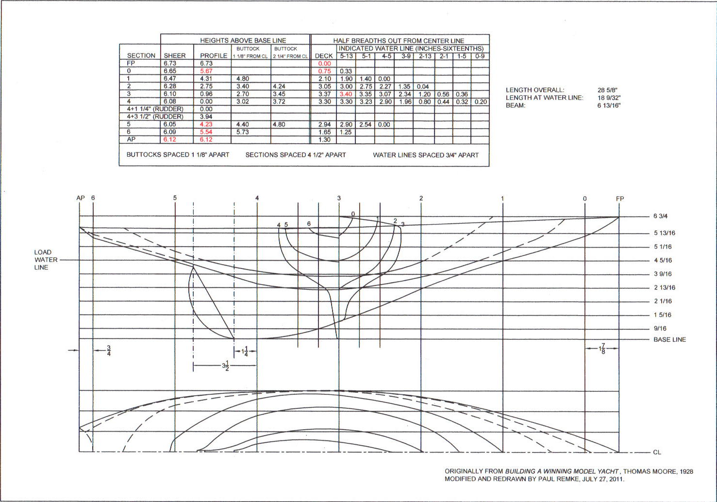
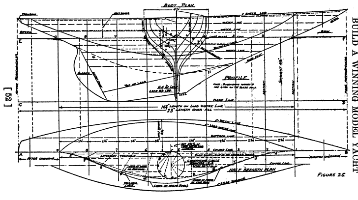
The curve of areas for a hull is a graph that displays how the displacement, or underwater volume, of the hull is distributed along its length. The horizontal axis of the plot represents the load water line. The vertical axis represents the area of an underwater section of the hull at that particular point. The areas are taken off the section plans. In actual practice, the areas are sampled at fixed intervals (e.g., the stations), and a smooth curve is fitted to the points. In the drawing by Thomas Moore (Fig. 26 from Traditional Model Yacht Design), the curve of areas is (as is common) overlaid on the half breadth plan.
The curve of areas clearly has a strong relationship to the wave making and resistance of a hull. If the curve rises too sharply at the bow, the hull will be “bluff bowed” and push water before it. Likewise, if it drops too sharply at the stern, there will be significant turbulence aft, as when a square-sterned boat “squats” over the limit of its design speed. Conversely, a curve of areas that rises too slowly at the bow will lead to “plunging” and excessive pitching.
Archer asserted (based on some fairly imaginative mathematical reasoning) that the curve of areas should itself resemble a wave line. It had already been learned by trial and error that the section of a yacht with the greatest area (the midbody) should be at about 6/10 of its length. Archer further argued that the curve of areas ahead of the midbody should follow the mathematical curve called a curve of versed sines and that after it should be what mathematicians call a trochoid.
These curves are generated geometrically, as shown in the diagrams. They are both constructed from a circle and a line. The line is the length of the load water line and the circle is placed at the location of the midbody. The line is divided into equal parts (usually corresponding to the position of the stations; a′, b′, and c′ in the diagrams) and the circumference of the circle is divided equally into the same number of parts (a, b, and c) as the line was. The upper diagram shows how to develop the curve of versed sines. A series of rectangles is drawn (e.g., a to a′′ to a′) and the upper corners are connected as shown. The trochoid in the lower diagram is a little more complicated. Lines are drawn from the point A where the circle touches the line, such as A to a. A second line, of the same length and parallel to it (a′ to a′′) is constructed. As before, the corners are connected with a smooth curve.
The wave theory was attractive to Victorian naval architects because it was fundamentally geometric and therefore could be implemented using the drafting instruments of the time. It also had a nice mystical ring to it, and, most importantly, produced fast, steady, and good-looking boats. It fell out of favor in the early 20th century as more scientific evidence was gathered from towing model hulls in test tanks.