Article, photo, and illustrations by John Henderson
One of the very first steps in setting up a new boat is getting the helm to “balance.” Balance refers to how the boat tracks without constant adjustments to the rudder. Balance preferences may be subtly different for different skippers. Some folks like a boat to track in a straight line when left to itself. Others prefer a slight tendency to “head up” (turn toward the wind) in response to a puff. No one likes a boat that tends to head down (turn away from the wind).
The argument for tracking straight
It is often the case that at least part of the race course is far enough away that seeing the model boat’s behavior is difficult. It can be reassuring if you know that the boat will continue in a straight line without rudder input. This is very difficult to achieve, which is why self-steering gear was invented to control models before the days of remote control. The force vectors from the sail and hull change with heel angle, so a puff or lull will alter the course unless the rudder is moved.
The argument for heading up
This is known as “weather helm”, because you move the tiller to weather (toward the wind) to bring the boat back to its course. For dinghies, this behavior can be a safety feature because it turns the boat so that the sails luff in a strong puff, even if the skipper fails to react. For models, the existence of weather helm can be a form of feedback to the skipper, because it gives a visual indication of the forces of wind and water on the model when we lack other kinds of feedback. One can even argue that a small amount of weather helm helps a boat get to windward, because the required small rudder offset to keep the boat on a straight course actually moves the stern a little to weather and it imposes a similar favorable angle of attack to the keel. Note that I said small rudder offset—a large offset just generates drag.
The argument for heading down
There is none. This is called “lee helm” and should be avoided. A boat with lee helm wants to head away from the wind in a puff, which increases the heeling forces at a time when they probably should be decreased. Course corrections require turning the rudder in a direction that moves the stern to leeward, which is the opposite of what you want to do on the upwind leg.
Achieving helm balance depends on establishing the right relationship between the Center of Effort (CE) of the sail plan and the Center of Lateral Resistance (CLR) of the hull. We will discuss first how to locate these Centers and then consider the optimum relative positions.
Finding the Center of Lateral Resistance (CLR) of the hull
I will briefly describe the traditional methods and then introduce a third method that I find superior.
The intuitive approach is to float the hull and push on the side with one finger. Move your finger toward the bow or stern to find the spot that causes the boat to translate sideways without twisting. This is the CLR. The problem with this method is that it depends on having a completed hull, so fixing surprises is difficult.
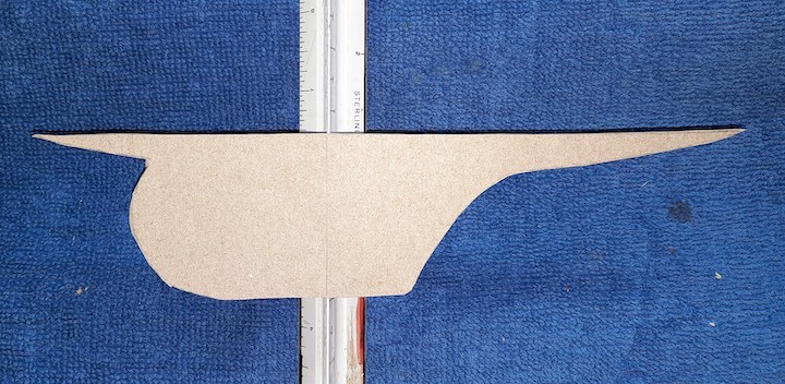
The usual textbook method of finding the CLR is to balance a cut-out of the profile view of the hull’s underbody on a straight-edge (a ruler) that is perpendicular to the waterline. The balance point is the CLR. The underbody shape is traced from the profile lines drawing; the “underbody” is all the parts of the hull from the waterline downward. Do not include the topsides (the hull that is above the waterline). You must use stiff plywood or cardboard.
My own preferred method to determine the CLR location is something that I have not found described in the literature, but which I think is analogous to the usual method of finding the Longitudinal Center of Buoyancy. I use Simpson’s Rule (the same rule we have used for displacement calculations, except that now we will use it to calculate area instead of volume). An explanation of Simpson’s Rule can be found in many books (e.g., Skene’s Elements of Yacht Design) and also in the US VMYG online Design articles at https://usvmyg.org/articles/planning-and-building-scale-models-that-sail-part-2-design-calculations/. Instead of using the sections drawings to measure the area of each section below the waterline, we will use the profile drawing to measure the linear depth at each section from the waterline down to the keel. The same section numbering conventions and Simpson multipliers apply. The measurements are taken directly from the profile view in the plans, and the calculations take about 15 minutes.
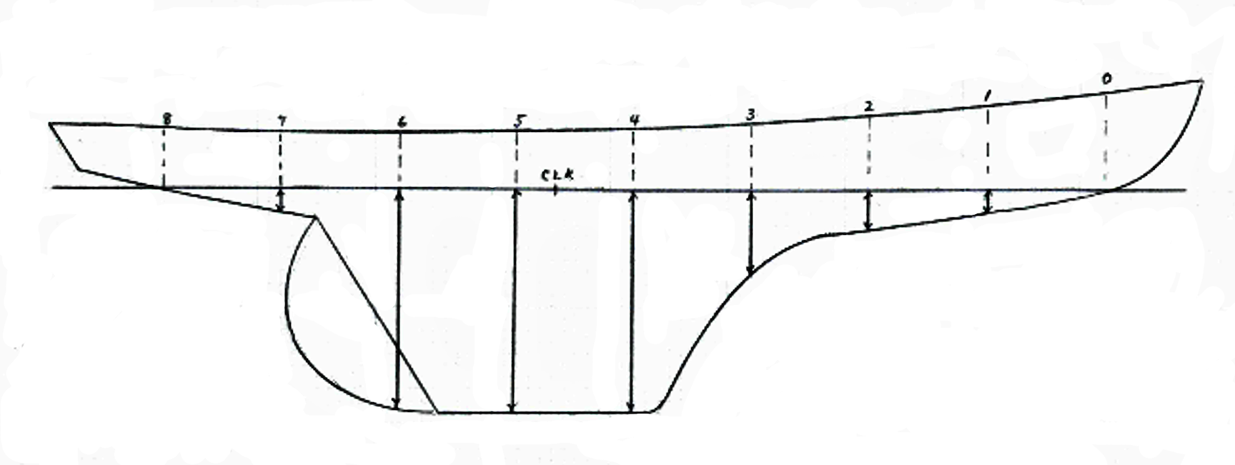
Fig. 1 shows a profile of an example hull containing only the lines relevant to this discussion. The positions of sections 0 through 8 are indicated. The solid portions of these lines, with arrowheads at each end, are the below-waterline station “depths” that are used to compute the CLR. (Note that the particular numbers for the example in Table 1 refer to a 42-in Unrestricted Class model that I am designing and building based on LF Herreshoff’s Stuart Knockabout. Fig. 1 is a representation, including some of my modifications. The original plans are available from The Mystic Seaport Museum.)
The section depth measurements are entered into a Table like Table 1.
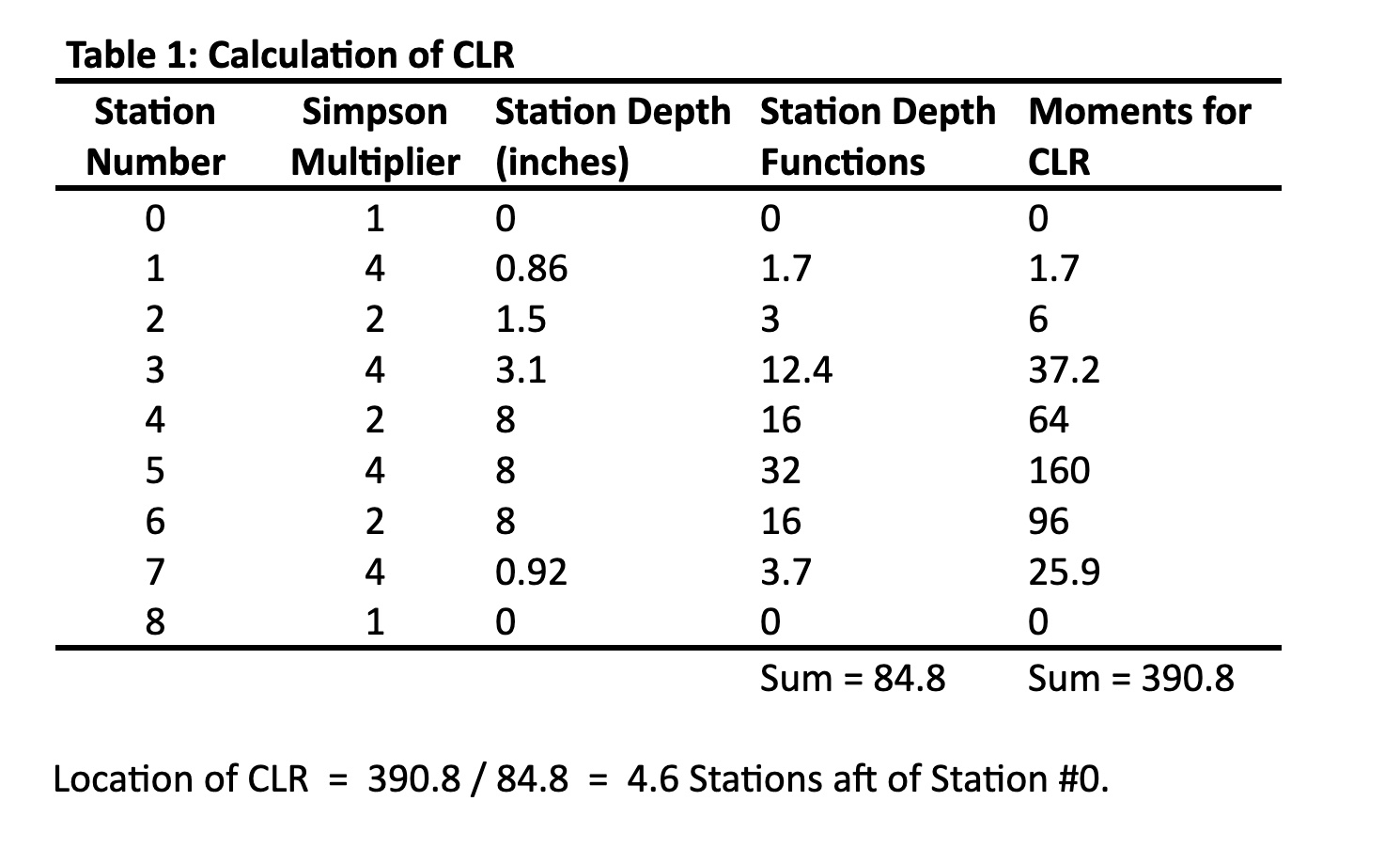
The first column is the Station numbers, from Station #0 up to the station at the aft end of the LWL, which must have an even number. The second column shows Simpson’s Multipliers – note the pattern of 1,4,2,4,…2,4,1. The third column lists the LWL-to-keel distances for each station (called “station depth”). The fourth column (“Functions”) is the result of multiplying each station depth by its corresponding Simpson Multiplier. The fifth column (“Moments”) is the product of each Function and the Station Number from the first column. Sum up the column of Station Functions and also sum the column of Moments. The position of the CLR is found by dividing the sum of Moments by the sum of Functions. Note that this result is the number of stations (and fractions thereof) aft of Station #0, so a result of 4.6 stations aft of #0 means that the CLR is 0.6 times the station spacing aft of Section #4, as indicated in Fig. 1.
There is discussion in the literature (and some disagreement) about whether or not the rudder should be included in this underbody profile shape. For models—which typically have an oversize rudder relative to full-size boats—I think the rudder should be included. I base this on observations of my own models. A compromise argument can be made to use half of the rudder’s profile area.
I should note that the accuracy of this CLR calculation improves as you increase the number of station depth measurements. For example, with reference to Fig. 1, you will notice that virtually the entirety of the rudder lies between Stations #6 and #7, so the shape of the rudder is not really captured by this set of sections. It would be better to double the number of sections (which would locate a new section midway between #6 and #7) so that the rudder area will be measured. Note that you cannot simply add a section where you might like one. The station spacing must be uniform over the entire LWL, so stations must be added between all of the existing stations. (In fact, when calculating for the actual model, I used 16 stations instead of the 8 in this deliberately abbreviated example—and the CLR moved from 4.6 to 4.7 stations aft of #0.)
It is easy to add more such vertical lines to the profile view on the plan, and there is no need to draw the shapes of these new sections on the rest of the drawings.
The increased accuracy that a greater number of stations provides is likely important for underbodies with high aspect ratio fins and separate rudders. We want to capture at least some of the details of their shapes. There might also be cases where there is a gap between the bottom of the hull and the trailing edge of the rudder or between the hull and a section of the ballast bulb. In these cases, the “depths” recorded in Table 1 should be the sum of all the elements (including rudder or fin) that are crossed by the section lines, so add the dimension of (for example) a ballast bulb to the hull measurement above it.
Finding the Center of Effort (CE) of the sail plan
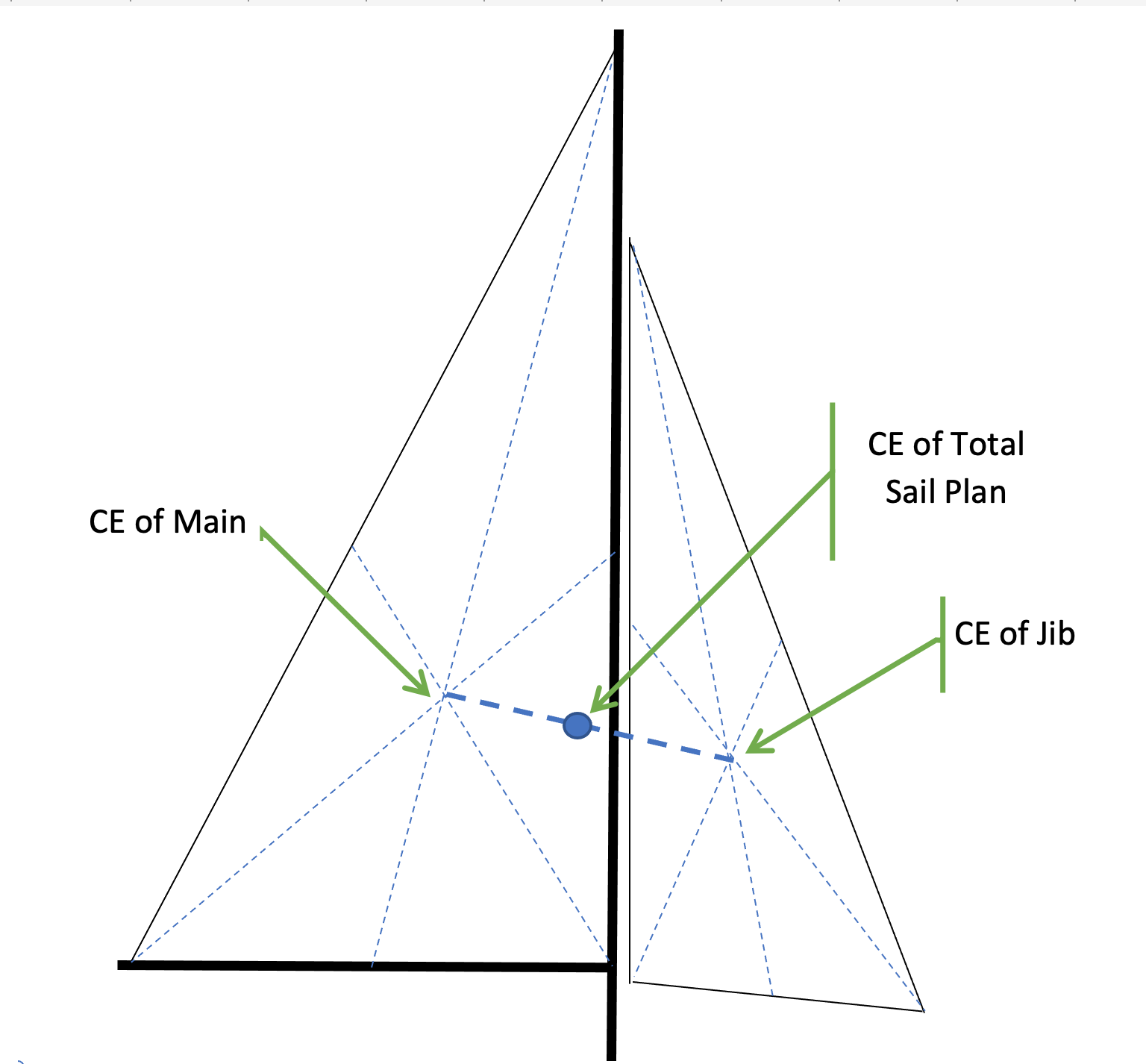
The process for locating the CE of the sail plan is well-documented, including in the Design section of our US VMYG website (see reference above), from which this description is taken. Referring to Fig. 2:
- Create an accurate drawing of the sail plan, including main and jib. This could be much smaller than your actual model, but it must be scaled from your model plans.
- For each sail, draw lines from each corner (tack, clew, head) to the center of the opposite edge of the sail. The CE for that sail is located where these lines meet.
- The CE for the entire sail plan is located on a line that joins the individual CE’s, and its exact location must be “weighted” by the relative areas of the two sails. For example—and here I will compute the distance by which the total CE is aft of the mast, which is:
{[area of main] x [dist. of its CE aft of mast] – [area of jib] x [dist. of its CE forward of mast]} / {total sail area}
Relative positions of CLR and CE
It might seem logical that the CE and CLR should be located at the same fore-and-aft position along the length of the hull in order to make the boat track straight. In general, I think that intuition is wrong. For most hulls and most rig types, the CE should be forward of the CLR. I have read various rules of thumb, but a consensus that seems supported by my modeling experience is that the CE should be forward of the CLR by an amount that is somewhere between 12 and 17% of the waterline length (LWL), at least for sloops. This is called “lead.” I have very limited experience with other rig types (e.g., schooners), but what I have read and my own models’ behavior indicate that the “lead” for multi-mast rigs should be smaller, perhaps around 5% of the LWL.
This guidance is far from precise, so it bears comment. I note that even professional designers of full-size yachts (at least in the days before computational analysis) did not always get this quite right, and new yachts went back to the building yard to have keels modified or masts moved. The problem is that the static analysis above, with its simple profile drawings of upright hulls with sails trimmed inboard to the centerline, is really an approximation of the dynamic situation when the boat is underway.
In any but the very lightest breezes, the boat will heel. This means that the CE of the sails will be offset to leeward, not directly over the center of the boat. The driving force from the sails will therefore be offset in a way that turns the boat to windward. This is weather helm, as we described at the beginning of this essay. One way to reduce this weather helm is to move the CE of the sails forward of the CLR. The difficult part, however, is to decide how great this “lead” should be, because the amount of helm depends on the heel angle, as well as skipper preferences, and it is not likely to be optimum over a wide range of wind conditions. I note that most full-size keelboats in my experience have lee helm in very light air, which is the reason that crews of smaller keelboats (for example the J/24) usually sit to leeward to induce heel (and hence the appropriate weather helm) in light air. We can’t do this with models, but we can adjust the mast position—and hence the CE—differently for light and heavy air.
Further complicating the trade-offs is the realization that the CE is likely to move forward when the sails are trimmed to practical (off-centerline) working angles, possibly causing a bit of lee helm that may or may not mitigate some of the weather helm effects of heeling.
Another variable is the shape that the hull presents to the water when it is heeled. The upright waterline is symmetrical about the centerline, but the “heeled waterline” is definitely not, nor is the bow wave. The asymmetric shape tends to turn the boat to weather, also supporting the case for the CE to be moved forward.
What does this mean for models?
When we are designing a model from scratch, we have maximum flexibility to locate both CLR and CE, but a scale model may cause difficulty. If we deepen the keel, as we often do for stability, or if we enlarge the rudder for better control, we will likely change the CLR. If we reduce the rig size, we may change the CE. We may, therefore, want to alter either or both of the keel profile or the mast position. The above discussion can help quantify our thinking.
Even if we do a wonderful job of optimization, we will likely still want to provide flexibility in the mast position to account for different wind strengths. We can also affect the CE with mast rake. The position of the jib tack also enters the equation.
It is my belief that getting the helm balance right is the first step in tuning. Optimizing sail shape and trim angles depends on this fundamental set-up, although helm balance is also affected by sail shape and trim, so there is feedback in optimizing the whole system.
If it were easy, we’d probably find another hobby.