Part I: Designing — Sheer Plan — Half-Breadth Plan — Body Plan — Centres of Gravity and Displacement
By way of preface to those readers of Amateur Work who can’t think what people can see in such “childish amusement,” I will just say, what, no doubt, they have seen pasted about in a good many streets, ”Try it” and if their first model is one that they can pit against existing ones with success, and if they can make her go where they will the first time she is put into the water, I will say they are right, it is a childish amusement; but until that is done, I must still hold on to my opinion, that model building and sailing is as scientific and amusing a hobby, combining both in and out- door pleasure, as can be found. “So, there,” as the tender sex have it. And now to work. I shall take it for granted that you know how to make a mechanical drawing, since it has been explained in this magazine, for before you can attempt any- thing in models you must draw them out.
There are three plans of a model to be drawn out. Firstly, the sheer plan; this represents a view of the boat when looking at it directly from the side, as shown in Fig. 1. Then there is the half-breadth plan, which is a view of the half of the model (Fig. 2), looking at it from underneath. And, thirdly, comes the body plan (Fig. 3), which is the view from the front on the left half of the plan, and the view from behind the model on the right half.
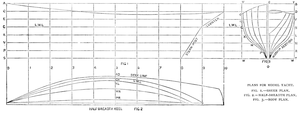
We must begin with the sheer plan. The shape of this depends in a great measure upon taste, but for the first model it would be better to keep to the illustration shown here. Having selected a sheet of paper, to take the full size of the model if possible, (if not you will have to draw to scale), and glued or pinned it on the board, draw at about 6 inches from the top a line right across the paper, and draw it pretty heavily, for you must work all other lines from this one. Mark this on each end L. W. L., which means load water line, and is to rep- resent the surface of the water, when the model, with all her rigging, and quite complete in fact, is stationary in the water. But, before going any further, you must determine upon the dimensions your yacht is to be. A very good size is 2 feet 6 inches over all that is to say — from stem to end of counter, and, as many model yacht clubs adhere to this size, I should, I think, follow their example. The beam, or breadth, should be about one fourth of the length. Fancy dictates here in a very great measure, as it does in a great many things in model yacht building. Some like a broad beam and some a narrow beam; but experiencia docet applies here very well, and as most probably you are without experiencia, keep to the “4 to 1” dimensions. I should therefore make her 7 inch beam, so as to keep to an even figure. Now for the depth below the water line, take about one-seventh of the length, that will make it 4 inches deep. This is merely to the bottom of the wooden part of your model, and does not include the lead keel, which will come on afterwards. For the height out of water you must study circumstances a little. You see, to make a boat look pretty, there is always a certain amount of what is called “sheer” given her—that is to say, a certain curve beginning high at the bow, falling towards the centre, and then rising again at the stern. Therefore you must have a fixed dimension for your height above water at the stem and draw in your sheer according to fancy afterwards. Then again too high a stem looks bad, and moreover is apt to hold the wind and retard the boat’s speed, whereas too low a stem does not afford sufficient support to her if she has a press of canvas on. I think about 3 inches for a 2 feet 6 inches model is very fair, and the sheer you must determine yourself, or take it from the diagram here. Now you may begin drawing out in earnest. Parallel to your load water line draw 4 lines below each other, each 1 inch apart from the other. The lower line will then represent the bottom of the keel, 4 inches below the waterline. Now draw three lines above the load waterline, also 1 inch apart. The top line would then represent the deck line if the deck were without sheer, but now simply represents the 3 inches at the bow.
These lines will represent so many planes cutting the boat parallel to the surface of the water.
The next thing to draw in is the stem, or bow; keep this about a couple of inches from the edge of your paper, and never mind, for the present, the curve at the foot. Simply draw a straight line vertical to the load water line. Now, at distances of 3 inches, draw lines parallel to the bow—that is, vertical to the load water line, to the extent of 30 inches, which will give you eleven lines, and ten spaces of 3 inches each, which will be the exact length of your model. The counter, or over- hanging part, should be about 3 inches, so draw that in to your own fancy, and consult your fancy also on the “rake,” or slope of the stern- post, which should have more or less rake to allow the rudder to swing easily, of which more hereafter.
The body plan is drawn on the extended horizontal lines of the sheer plan, and the half-breadth plan on the extended vertical lines of the same.
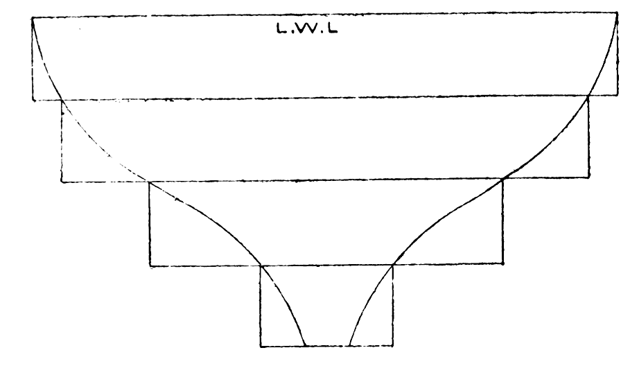
Now, there is one part of a ship, looking at her endways, which is larger than any other part, and, past which no other part of the vessel is visible: this is termed the “midship section,” and is represented by the outside lines in the body plan. We intend making the midship section on the line 5, which will be rather abaft the centre of the load water line. Some builders prefer a long “entrance,” which necessitates having the midship section far back; while others like a short “entrance” and a long “run,” which means hav- ing the midship section well forward, so that the bow lines converge at a greater angle than the stern lines. Now draw a centre line, XY, on the half breadth plan, and on 5 mark off from XY 3 1/2 inches, which is the half- breadth of your vessel. Above XY draw a line parallel to it, and at a distance of 1/4 inch, to represent the half-breadth of the keel, and then with a thin spline or batten draw in the deck line on the half-breadth plan to pass through the dot on 5, and fall nicely into the keel line in front, and rounded at the stern for the counter. You had, for the present, better keep as near as possible to the diagram shown here; but when you get a little more accustomed to drawing in these curves you will be able to judge for yourself if a line is what, in shipbuilding parlance, they call “pretty.” Leave the half- breadth plan for a’ little while, and on the body plan draw a vertical centre line, O O, and on each side of it draw lines at 1/4 in. distant, and parallel to it, to represent the keel. One part of this body plan, you must remember, is the forepart of the vessel, and the other half the after part. Now on the load water line, still in the body plan, on each side of the centre line mark off 3 1/2 inches, which is half the beam, and, starting from this point, draw in by hand a curve somewhat similar to the one in the diagram, and see that there are no “lumps” in it, and that it falls nicely into the straight line of the keel at the bottom. Having rubbed this out and put it in again several times till satisfactory, rub it nearly out once more, and put in definitely with curves, so that you have a definite spot where the curve crosses each horizon- tal section. Do this on each side of the centre line O O. Go back again to the half-breadth plan, and with your dividers mark off on 5 from XY the places where the midship section, which you have just drawn in, cuts each of the horizontal sections—that is to say, the distances from O O to C, to E, to G, to K, to M, and to P.Through these points, or rather through the point G firstly (which is the load waterline), draw a curve to the bow, and to line 9, taking care to make it fall nicely into the straight of the stem and stern posts, the thicknesses of which are represented by the line above XY. You must be particularly careful to draw this curve in nicely since all the other lines are worked from it, and let me impress on you that india-rubber is, in the present state of the market, a cheap article, therefore you need not be afraid of wasting it by rubbing the line out again, if not to your fancy. There must be no “lumps” in the curve, and no sudden rise or fall; it must all be gradual. To find out if the line is “fair,” you need only look along it, with your eye nearly on a level with the paper, and any little inaccuracies will at once become perceptible. Having “faired” this to your satisfaction, mark off from O O (in the body plan), on the line G (the load water line), the respective distances from X Y (in the half-breadth plan), to the points where the curve, which you have just drawn in, cuts the lines 4, 3, 2, 1. Treat the after part of the load water line in the same manner, but mark it off on the right-hand side of the body plan.
Now draw in the other curves in the half-breadth plan through the points already marked on 5, trying to keep them as little hollow as possible. These lines you must simply guess at to begin with, but after a little practice your eye will tell you very nearly where to draw them in. After this is done, mark off from O O on C, E, G, K, M, and P, the distances from X Y, along 4, to where the curves C, E, G, K, M, and P, respectively cross 4. Through the points thus obtained draw a curve, and if the curve thus drawn falls in nicely, with- out lumps or kinks, your lines in the half-breadth plan will be pretty nearly right. Treat the lines 3, 2, 1, on to the left-hand side of the body plan, and 6, 7, 8, 9, on to the right-hand side, in the same way, and if each curve comes in nicely your lines will be right; if they do not fall in well, you will have to alter the “waterlines,” as they are termed, in the half-breadth plan, until the body lines can be faired easily.
It will, I am sure, entail a good deal of rubbing out and putting in again, before your lines will come right, but do not be afraid of that, since it makes your work much easier when you come to the wood-working part of the business, and do not say to yourself, “Oh! bother it, I can’t get that right on the drawing, but it will come in all square in the wood.” It is a fallacy, I can assure you; you would never have been more mistaken than when you said that. If your drawing is not correct, your wood-work cannot be correct, and therefore you will be guessing at things all through the job, instead of having everything down on paper in a respectable manner. So put that notion out of your head, and say it must come right in the drawing, and when it is right you will be a great deal more satisfied with yourself, I am sure.
You have not yet, by the bye, drawn in on the body plan, the sheer, therefore measure off the heights from the load water line to the sheer in the sheer plan on the various lines, 1, 2, 3, 4, 5, etc., and mark them off on their corresponding lines in the body plan, and the distances from O O to 1, 2, 3, etc.; you will take, of course, from X Y, in the half-breadth plan, to the deck line along 1, 2, 3, etc., there. Having joined the points thus obtained with a nice curve, I think your drawing is finished. The keel you can only put in afterwards, when you know the weight of lead your boat will carry, which will be more or less, according as you have made your lines “fuller” or “finer.”
In the next paper, then, I shall begin with the building of the model; but before we come to that, a few words on the shape of models would not be out of place. Models must be considered as racing yachts, and, therefore, unlike merchant vessels, carrying power, or rather “cargo space,” is no object. The great thing in models is to get your lines as nice as possible, and, to my own idea, the less hollow a line the better it is. Then again, as I said before, some like the midship section for- ward of the half-length of the boat, while others, myself included, prefer it abaft.
It appears to me that, considering a vessel is nothing more or less than a wedge driven through the water, the smaller angle that wedge has the easier it will separate the particles of water with a given driving power; and then, again, as water will close up again more easily than it will be separated, so the quicker the lines in the stern con- verge, the better, to a certain extent. In both these, as in every other case, excess is not meant, and you must, therefore, not make too long an “entrance” or too short a “run.”
With regard to the proportion of beam to length, there are one or two points to be considered before deciding this matter. Firstly, beam gives a vessel greater carrying power, and, to a certain extent, greater “stability” (by stability is meant the power a vessel has of resisting any force which tends to press it over on its side, when in the water, of course) —or, I should rather say, greater “stiffness.” A broad and shallow vessel is “stiffer” up to a certain angle of inclination than a narrow and deep boat, but press both over to that angle and you will find that past that point the broad vessel will perhaps capsize easily, whereas it will be impossible to capsize the narrow but deep one, since she will always right herself again. Now this is easily explained when you know that there are two very important points, or “centres,” in a ship: the one known as the “centre of displacement,” which is in reality the centre of gravity of the mass of water which the ship “dis- places,” or takes the place of, when she is put into the water i and the other the “centre of gravity” of the ship itself. When a ship heels over you can readily see that her centre of displacement will shift, because the shape of the water she displaces alters as her own shape differs under water, according to the various angles of inclination. Therefore in a shallow ship, where the centres of gravity and displacement are close together, the centre of displacement has to shift very little to cause the vessel to capsize; but in a deep boat it has to shift a great deal, since the two centres are further apart. So, then, in a model you must com- bine the qualities of a broad vessel and a deep one; but take care not to get her too broad, because the lines will not be fine enough in that case, nor must she be too deep, since the more surface a boat has in the water the greater is the resistance caused by the friction of the water on her sides to her headway.
I am afraid space will not permit me to say more about designing, but practice will assist you more than anything else, and if you can reason a few points out for yourself, so much the better. About the centres I shall have more to say further on, when we come to building.
Part II. The Hull — Materials — “Dug Out” Mode of Building — Block — Hollowing Out Sections — Layer Method — Adjustment of Pieces– Marking Off Water Lines — Roughing Out — Gluing Layers — Deck — Keel
I gave you in my last paper the way to put your model on paper. I will now endeavour to give you full instructions how to carry your design out in the wood.
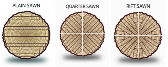
The very first thing is to get wood that will not only stand damp well without shrinking, but will also be free from resinous matter and knots, and allow itself at the same time to be easily worked. My first model I made of white pine, and you can fancy it was more or less “riling” when one day she came to the shore, after I had been sailing her for some two or three hours, half full of water, the wood having shrunk, and the seams opened.
Perhaps had the seams been properly made, as I afterwards learnt to make them, the consequences would not have been so bad, but still I never used white pine again, and should advise my readers to avoid it. The best stuff you can get is Canadian; yellow pine; and when you go to buy it try and get a friend in the wood trade to go with you if you have one. I take it for granted you know enough about wood working to be aware that knots are things which can hardly be termed pleasant to work, so try and get your stuff with as few as possible, even if you have to pay a little more for picking and choosing.
Now there are two ways of building a model that I am going to explain. The first way is called “dug out,” and is made from a solid block of wood.
The other way is the “layer” fashion, and consists in fixing a series of planks one on the other, and cutting the model out then. Of course, there are other ways of building, for instance, like a real vessel, and then making two halves, and joining them afterwards, and the diagonal method, but none touch the “layer” fashion.
Firstly, then, the block. Having procured a nice piece of wood square it up exactly to the outside dimensions of your drawing, which will be 30 inches by 7 inches by 7 inches, and mark off on each side the horizontal and vertical lines, and the slope of the counter; and stern-post, and on each end put a centre line down. Then mark off the thickness of the keel, and the shape of your deck on the bottom and top respectively, and now you can begin to work with your tools. First, saw out pretty close to the line the part between the counter and stern-post, and then with a bradawl bore at each point where the vertical and horizon- tal sections cross, on the block, to a depth corresponding with the distance in the body plan, that the section on which you are boring is from the outside line, representing the square section of the block, or, in other words, measure off from the point of the bradawl, the distance the line VW is from section No. 1 on the respective lines C, E, G, K, M, P, and bore down to those various distances on the corresponding lines on the block. Treat the other sections in the same manner, boring down on each side of your piece of wood. You can either mark off the distance on the bradawl with chalk, or you can measure the distance, and put your nail there; the former is preferable though, I think. You can now set to with your gouges, of which you should have a fair assortment, both inside and outside ground, and pare off till you come to the bottom of the holes made with the bradawl.
Rough it out firstly, and then smooth it up after- wards, carefully work- ing across the curves, and not parallel o the water lines. The counter will have to be worked in gradually and carefully so as to run in nicely with the stern lines. Take care not to cut into the keel nor into the stem and sternposts. When it you have got her fairly into shape you can begin to hollow her out. Bore, with a centre bit, a couple of holes, one in the bow and the other in the stern, taking care not to go too deep, and having marked the thickness of your side all round the boat (about 3/ 8 of an inch), begin with a pretty quick gouge to scoop out first from one end and then from the other, letting the pieces split off in the centre. Take care you don’t go through the side, and keep on feeling, as you go down, how much wood you have to work on. Should you be unlucky enough to let your gouge slip through the side, patch it from the inside with a piece of wood, and the glue which I shall describe further on for the “layer” method. When you have hollowed her well out, finish up the outside with a rasp, and bits of bro- ken glass, and, lastly, with sandpaper, beginning with a coarse and ending with the finest, until there is not a: lump or hollow or angle of any sort on her. Now mark off the sheer on each side, and run that off with a spoke- shave; your model will then be finished, but I am afraid it will take you rather longer to do than to read how it is done. So much for the dug-out t method, of which I am not an advocate, but which, like everything else, has its advantages and disadvantages.
For the “layer method you must use the same yellow pine, or rather not the same, as that would be rather impossible; but I should say the same sort of yellow pine, viz., Canadian. In this method you get certain number of pieces, to correspond with the number of spaces between your water lines, and each the thickness of those spaces; in this case it will be seven pieces, each an inch thick. You will therefore have to get our wood a little thicker than an inch, so that you can plane it up an exact inch; and it will be a nice little job for you, if you can use your planes at all, to face these pieces up without the slightest winding on them, and to an even thickness throughout. If you cannot do this yourself, get a carpenter to do it for you, he will not charge much.
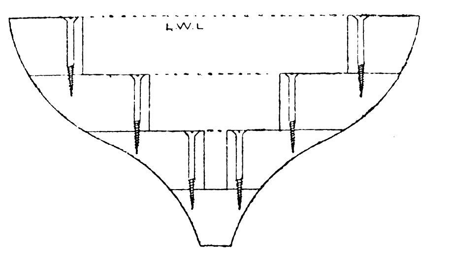
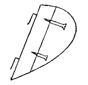
The widths of these pieces need not all be the same, as you will see by reference to Fig. 4; therefore, you must adjust your wood accordingly. Having got these several pieces in order, mark on the top one the shape of the deck line. On the next piece mark off the shape of the first water line; on the third piece, the shape of the third water line, and so on, till the last piece, on the under side of which will have to be marked the thickness of the keel. The thickness of the stem and stern posts must also be marked on the ends of each piece. I omitted to mention that a centre line should be drawn right round each piece of wood, and the midship section should also be marked right round.
To mark off the water lines from the drawing to the wood, you will have to mark off the different sections on the top side of each piece, and then measure from the centre lines the respective dis- tances that the different water lines are on each section from X Y, and then put in the curves with a spline. All this being done, take each layer and cut close to the line with a keyhole saw, cutting off all the four corners of the layer, and then with a spokeshave finish up carefully to the line. To test if you have marked off correctly the water lines, take each layer and place it on the half breadth plan, so that the centre line on that layer corresponds with the centre line on the drawing, and No. 1 layer should fall exactly along the deck line; No. 2 along the first water line, and so on.
Now take the bottom layer and place the last but one on it, so that the centre lines and midship sections correspond exactly, and screw them together with screw at each end, Fig. 6. (As the layers are 1 inch thick, a 1 1/2 inch No. 8 will be the best to use, and let them be of brass, not iron.) Then mark off on the midship section line a distance from each edge, where you can put a screw into the section underneath, without fear of its coming through the side, Fig. 5. Treat all the layers in the same fashion, and you will then have them all screwed together with four screws in each layer, two at the ends and two at the sides.
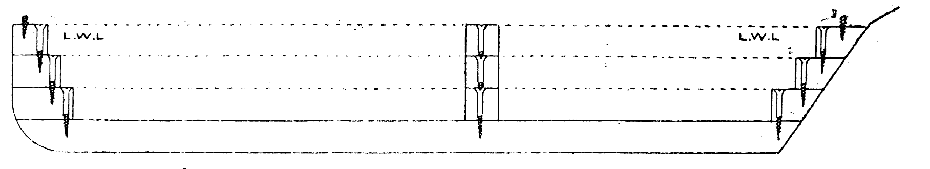
You can now begin paring off the corners and finishing up your model in the same manner as described for the “dug out,” taking care not to go beyond the proper water lines on the top side of each layer. When the roughing out is completed, take her to pieces again, e.g, unscrew the layers, and on each side of them mark all the way round the thickness your boat is to be — say 3/8 inch, taking care to leave space round the holes where the screws have been, as these will have to be put in again. Now, with a keyhole saw, cut as near round the underside mark as advisable, so as to leave nothing but the outside shape of each layer, and then pare off the rest from the top side with a gouge afterwards (Fig. 7); but, once more, do not forget the screw holes. The bottom layer is, of course, left intact.
You will now have to turn your attention to the glue with which to join the layers permanently.
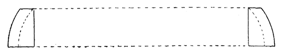
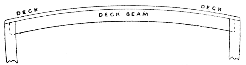
I came across some stuff quite accidentally, which answered the purpose “to a T.” It was the composition they use for fixing down oil-cloths, and can be bought in tins for 1s. each. This, diluted with a little spirits of wine, should be smeared on the bottom layer with a brush, and the next layer then screwed carefully into its former place. The others must be treated in the same manner, and when all are screwed together again, turn the boat upside down and place heavy weights on the keel. In this way it should be left to dry for about a couple of days, when you can begin to finish her up on the outside, and smooth her on the inside, just the same as for the “dug out.” Cut the sheer also as described before, and then think about your deck. But, first of all, prepare two little beams, about 1/ 2 inch deep and 1/4 inch or 3/8 inch wide, to go across the boat (Fig. 8), and let them into little niches made in the side. These tend to support the deck and, moreover, give it a curve, which not only looks prettier, but also allows the water to run off better.
Now, for the deck, get either a thin piece of mahogany, if you like the look of it, or if you prefer a white deck (which, by the way, is apt to soon get knocked about and look dirty), select a fine piece of white pine not thicker than 1/8 or 3/16 inch, and having planed it nice and smooth on both sides, rule the top side to imitate planks, with a hard lead pencil. Then give a coat of good copal varnish all over, top and bottom, and let it dry, but do not put it in a dusty place, or the appearance of the deck will be marred to a certain extent.
While that is drying, you must excuse me if I ask you to set to work at your hull again. I omitted to say anything about the keel, which you will, no doubt, have noticed, looked frightfully clumsy, at 1/2 inch thick.
You should leave it the 1/2 inch at the midship section, but from there taper it gradually both fore and aft, bringing the stem-post about 1/4 inch thick and the stern-post about 3/8 inch. The lines close up to the stem-post and keel will have to be fined away a little also. While we are about it, it may be as well to mention that a piece of hard wood, oak or teak, should be let into the front as a stem-post; the best way is to cut a piece of the present stem-post away, down to about the fifth water line, and screw the other in its place, put- ting a little cement in to make the joints, and trim- ming it into shape when in place.
By this time, I dare say your deck is dry; if so, screw it down with a small screw (brass 3/8, “No. 3”) at each end, and one or two in the sides, and then trim it off to the shape of your boat. It must not be fixed down permanently just yet, because you will have to get at the under side of it as you will presently see, but it should be taken off again when shaped down, as an undue strain is put upon the screws that are at present holding it in place. Take care you don’t loose your deck beams now, since they ought not to be fixed as it keeps the ship too rigid, there being always a certain amount of “working,” in even a model when she is “under weigh,” which it is as well not to pre- vent to too great an extent.
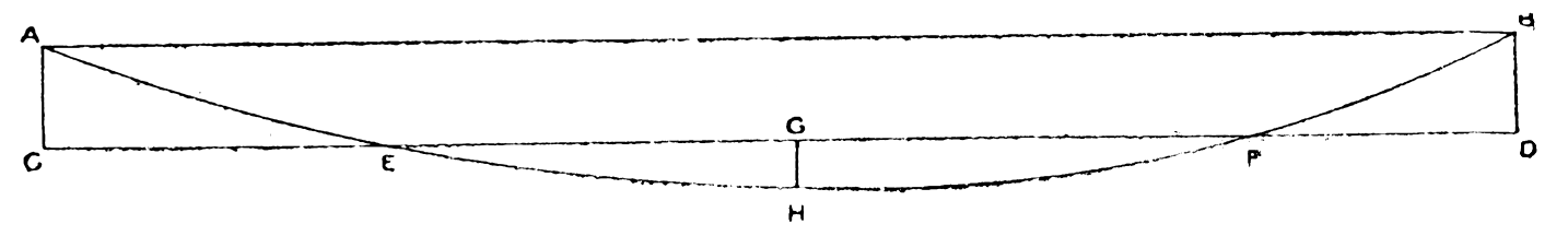
The keel will next require your attention, I think, but I shall only tell you in my next chapter how to find the weight that is really required to put her in proper trim, so I shall only suppose a certain amount now, and we shall see afterwards how far we are out. Suppose then you have found five pounds is required to bring her down to the water line, or rather say, suppose your keel is to weigh five pounds. Now a pound of lead contains 2.435 cubic inches; therefore, the cubic capacity of your keel would be 12.175 inches. Now the mean thick- ness is 3/16 inch, the mean depth would have to be 1.8 inch, therefore, since the length is 21 inches (as the other 3 inches must be left for the rounding of the “fore foot”). Now make a diagram like Fig. 9 (if there is room on your drawing do it on that) full size, by drawing a line1.8 inch away from the keel line, and making a parallelogram through the extreme points of the keel by the lines A C, B D.
Now strike a curve with your spline and divide the lower part of it by the line G H. Then, if you think A, C, E is about equal in area to F, G, H, and B, F, D to G, H, F, your keel curve will be about right, but if not, you must alter it till you think these parts are equal, making the keel rather larger than smaller, since you can always trim a piece off but can hardly stick a piece on.
Now round your forefoot to fall easily into the curve of the lead keel, and then you can set about getting it cast.
Make a nice smooth pattern of it, and do not for- get to make about four holes at different places right through, to admit of its being screwed on to the boat. If you go in for casting yourself, all the better, if not, get a founder to do it for you. When it is cast, weigh it, and I daresay it will not be very far out in its weight. Take off any superfluous weight with a spokeshave, and then trim it up nicely with a rasp, taking care to keep the surface which joins the boat flat and square with the centre line.
With a little putty underneath, screw the keel well home to the bottom of the boat with suitable screws, having first ascertained that it stands upright or rather straight with the centre line of the boat, because a crooked keel is out of the question.
I shall give you in my next, how to find the real weight of the keel, as I think, for this month, you have quite enough to do.
Part III: The Hull (Continued) — Painting — Lead Keel– Finishing Hull — Means of Propulsion — Centre of Lateral Resistance — Area of Sails
I promised to show you how to find the right weight of lead that is required for the keel, but you will have to rig your model, according to instructions which will come hereafter, before you can find it out properly; and I shall, therefore, have to imagine that the rigging part of the busi- ness is finished, and that you know the exact weight of your boat with all her gear, etc., except, of course, the lead keel. I should have liked, had space permitted me, to show you how to do this by figures or theoretically, but as it would take up too much room, it will have to be done practically –that is to say, by experiment.
Firstly, then, take your rigging down and the deck off (which, by the way, is not screwed quite down yet, but only held in place by a screw here and there) and give the hull a coat of ground paint inside and out, and when that is dry give it a sec- ond. Now mark your water line carefully on the model (taking the distances from the sheer plan) with a strong black pencil, and then screw your deck on as before, and put the rigging in place again.
You must then take her to some piece of water, or if you have a bath in the house that will receive her, all the better, and having supplied yourself with some weights, say a 4 lb., a 1 lb., two 1/2 lb., and some smaller weights,-put her afloat, and steadying her by the masts place as many weights along the centre of the deck as will bring her fairly down to the waterline.

Mark around the places lightly where these weights are, and take her out of the water again. You have, of course, taken note of the different amounts in the various places before taking her out of the water, so we will suppose that you had three weights on her, of 4 lb., 1 lb. and 2 lb., making altogether 5 1/2 lbs. Now measure the distance that the centre of the 4 lb. weight was from the stern, and do the same for the other two. Let us imagine these distances to have been, 4 lbs. at 10 inches from the end of the counter, the 1 lb. at a distance of 22 inches from the same place, and the 2 lb. at a distance of 24 inches. Multiply each of these weights by their respective distances, and add the products together, then divide by the total mass of the weights, and the quotient will be the distance that the centre of gravity of your lead keel has to be from the end of counter. Thus in this case,which you may call 13 1/2 inches.
Mind, this is the distance from the end of counter and not from the end of L. W. L., therefore, I should advise you to mark it at once on your drawing. Before you have your lead cast you should see that the centre of gravity of the pattern comes on the right place (that is, the place you have just found), for if it does not, you must alter the shape of the curve till it comes right, taking care not to increase the weight.
You can now set to work and finish the hull. Get some finely ground pumice powder, or get some pumice-stone and pound it to a fine powder your- self, and with a rubber of cloth and this powder rub the hull down, using a little water at the same time, until all the brush marks are out of the paint. A circular motion will be best for this, but it requires a fair amount of patience since the model must be like a piece of glass when done.
This is only the ground paint that you have smoothed, so you must consider what colour to paint your boat. A black top looks nicest to my idea, and a flesh colour for the bottom shows the black off very well; but you can do about that as you please. Lay two coats of the bottom colour on her, rubbing each coat down as before, and then if you intend painting the top side black run a pencil line along where the two colours are to meet. They should join above the water line all round the boat, but the line should be somewhat higher at the bow than at either the stern or midship section. To get this line on nicely, paste strips of paper along it, on the under side, and then you can paint away without fear of the paint get- ting below the line and spoiling the regularity of it.
For the black part you should not use ordinary paint, but get some of that stuff which is used for “ebonizing.” It is obtainable at almost any large colourman’s, and a small bottle will go a long way. This is preferable to paint, because it does not require rubbing down, and as the deck should be put on before the top is painted, there is no fear of spoiling the appearance of it.
The deck should be put on with putty for the joint, and screwed down at regular distances. If you do not like the appearance of the screw heads on the deck, they can be covered by a narrow beading of mahogany, fastened all the way round the edge with fine brads, and having here and there slots cut in to allow the water to run off the deck.
A coat of the best copal varnish over the whole will, I think, finish the hull. This varnish, though, should also be rubbed smooth, if it is found to be in the least lumpy when dry; and let me try and impress on you the necessity of rubbing down these coats of paint and varnish in a proper manner, because the rougher the outside of a ship is, or say rather a model, the more resistance she offers in going through the water, and, consequently, the slower she will go. But if this roughness is reduced to a minimum, as by patient scrubbing it can be done, the particles of water have nothing to lay hold of, and, therefore, the resistance is so much less, resulting in a greater speed with the same amount of driving power.
Talking of driving power reminds me that I have not yet mentioned anything about the “means of propulsion.”
When a boat is sailing, the forces of the wind acting on her sails can be brought to a resultant acting at a certain point in the plane of the sails termed the “centre of effort,” and the position of this point, in relation to another point, termed the “centre of lateral resistance,” plays a very important function in the sailing qualities of your model.
The “centre of lateral resistance” is a point below the L. W. L., in a plane passing vertically from stem to stern through the centre of the vessel, through which the resultant of all the forces of the water acting on the sides of the vessel when being pushed sideways through the water, acts. In fact, to make this a little clearer, if you could fasten a string to the centre of latera1 resistance, and pull the boat through the water sideways by it, she would come broadside on exactly, and would neither swerve to the right nor the left. You can there- fore easily see that, since the wind striking a vessel tends to drive it sideways through the water (called leeway), the centre of effort and the centre of lateral resistance should be in the same vertical line, for if the former were in front (fur- ther towards the bow) the vessel would, when sailing, tend to turn away from the wind, and thus lose headway; whereas, if the centre of effort were behind the centre of lateral resistance, she would “come up into the wind,” in both cases altering her course, which should be prevented as much as possible in model yachts, because you are not, unfortunately, on board to handle her yourself, and must therefore do all that when she is on shore.

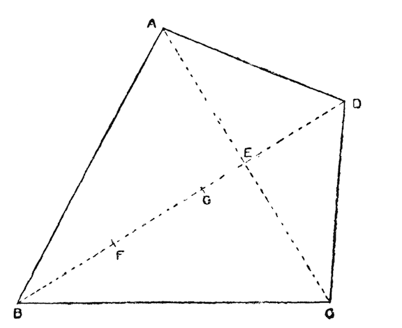
I will now, before I go into the different styles of rig, show you how to find these two rather important centres. Let us begin with the easiest, viz., the centre of lateral resistance. The best way for you to find this is to cut out in thin wood or card- board, the shape of your sheer plan under water, and find the. centre of gravity of that by suspend- ing it first from one corner and then from the other, the place where the strings cross being the centre of gravity, Fig. 10. Now mark this on the corresponding position in your sheer plan, and that will be the centre of lateral resistance. For the centre of effort you must first find the centre of gravity of each sail, as I will show you further on, and square all these centres down on to one horizontal line, and then multiply the area of each sail (which I will show you how to find presently) by the distance that the centre of gravity of that sail is (on the straight line) from the centre of gravity of the head sail. Add these different products together, and then divide by the sum of the areas of the sails, and the quotient will be the distance that the centre of effort of all the sails is from the centre of gravity of the head sail.
Thus, suppose you have three sails, and having found the centres of gravity and squared them down on to a horizontal line (say the L. W. L), work out the areas. We will imagine the area of No. 1 sail (head sail) to be 50 inches, and the area of No. 2, 120 inches, and of No. 3, 100 inches, and the distance of centre of gravity of No. 2 from centre of gravity of No. 1 to be 10 inches, and from No. 3 to No. 1 to be 20 inches.
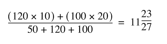
Theor not quite 12 inches; 12 inches is the distance of the “centre of effort” from the centre of gravity of No. 1 sail. This rule applies to any number of sails, topsails included.
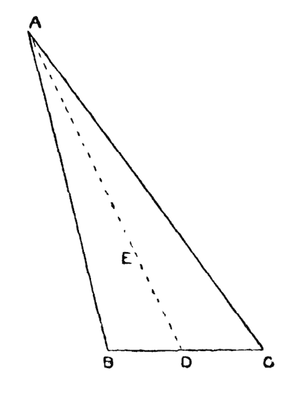
Now we will see how the centres of gravity1 of differently shaped sails are to be found. Let us take an ordinary triangular sail to begin with, as A B C, Fig. 11. Bisect any one side, say B C in D, and join the corner A, opposite the bisected side with the point of bisection D, Then divide D A into three equal parts; and the first point E, i.e., one- third of A D from D will be the centre of gravity of the triangle, or rather in your case of the sail.
For a four-sided sail, Fig. 13, you join D and A C, and from B mark off B F equal E D, and from C mark off G equal A E. Join F G and the centre of gravity of the triangle E F G (found as shown above) will be the centre of gravity of the whole sail. Should it happen that one of the diagonals, say D E, bisects the other A C, then mark off from B the distance B F equal to E D, and one-third of E F from E will be the centre of gravity, G, required, Fig. 12.
The next thing is to find the areas of your various sails, which is as simple as finding the centres of gravity.
Firstly, then, for a triangular sail. From any corner drop a perpendicular on to the opposite side, or, if necessary, the opposite side produced, and multi- ply the half-length of that perpendicular by the side on to which it has been dropped; so if your perpendicular measures 20 inches, and your base 7 inches, the area of the sail will be 20/2 X 7=70 inches. If the sail happens to have one angle a right angle, it will, of course, only be necessary to multiply the half length of one side adjoining the right angle by the whole length of the other side adjoining the right angle.
For four-sided sails simply draw a diagonal, dividing the sail into two triangles, and then find the area of each triangle separately, and the sum of these two areas will be the area of the whole sail.
In drawing out the sail plan you will have to guess first of all the shape and size of the various sails, and then when drawn out you will have to calculate the centre of effort, and see if it comes on the centre of lateral resistance, and if it does not, the sail plan must be altered till it does, by taking some off the fore sails, and adding to the other sails, or vice versa, as the case may be.
The total area of the sails should be about fifty times the area of the midship section below the load water line. If your vessel happens to be pretty deep, you can even increase it up to fifty- five or even more times; but if she is a pretty shallow boat keep it rather less. The area of the mid- ship section you must find approximately by making it into a triangle.
This refers merely to the “fine weather suit” of sails, but you should have three sets of sails for your model, or at all events two, each set being about a fifth less than the preceding one, so that your smallest set, “the storm suit,” will be three- fifths of the “fine weather suit.” I don’t believe in “reefing” model sails, because you can never get the sail to set properly when reefed, and it takes just as long to reef a sail as it does to take it off and bend a fresh one.
You will, of course, see at once why you want three sets (or let us say more than one set, because I know some people that are too lazy to make three sets, and think two almost more than enough). A model wants as much sail as possible in light winds, and, of course, when it comes over squally, some canvas must be taken in, and as tak- ing off either head or top sails would alter the position of the centre of effort, you must have exactly the same rig as for fine weather, only a little smaller, and when it comes to blow a gale she must have a smaller suit still.
I think I can commence now with the next chapter, and show you how, first of all, to choose your rig, and what rigs are most adapted for models, and then how to get your rigging put up; but, of course, you must draw the sail plan out first, and calculate a11 the necessary centres, etc., before you can begin rigging her.
Part IV. Rigging — Cutter — Schooner — Penzance Lugger
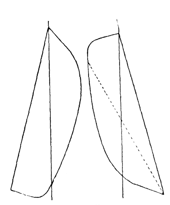
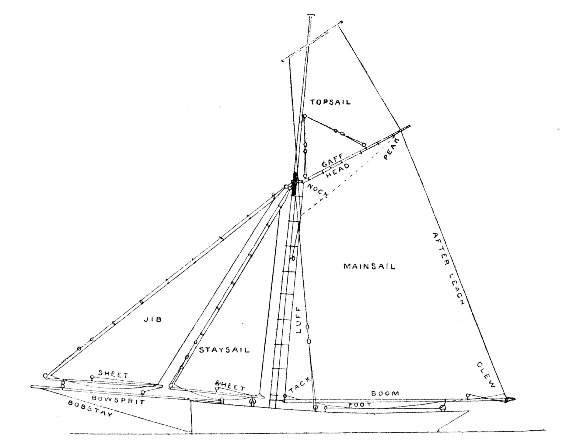
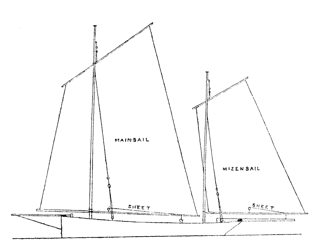
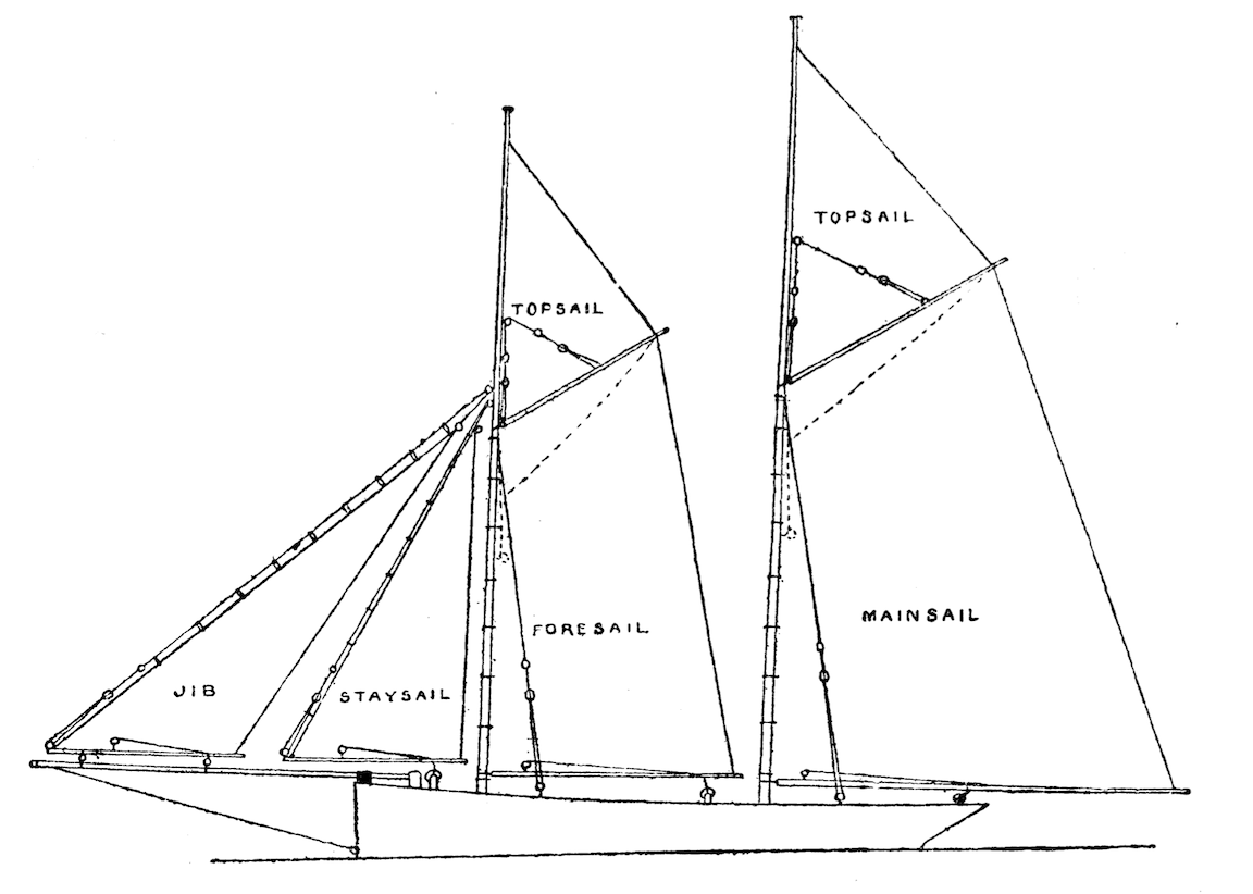
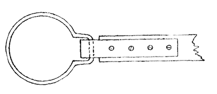
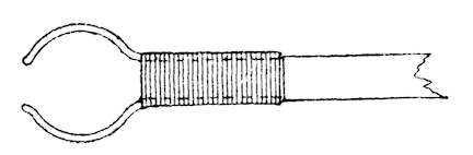
You must all know the shape of sails which constitute the most commonly used type of yacht—viz., the cutter’s (Fig. 14), but I doubt if you are as well acquainted with the Penzance lugger represented in Fig. 15. The schooner, which I daresay you also know, is shown in Fig. 16. Now these three are the best adapted for model yachts, and I shall there- fore confine myself to them, especially as space compels me. When you have done a little more in model sailing, you will begin to get ideas of your own with regard to the different styles of rig, and I hope will carry your ideas out, but for the first attempt or two you had better confine yourself to these three. The cutter’s, as I said before, is the style of rig most universally adopted, and you may there fore take it for granted, is considered by most yachtsmen the best; but I am an exception to the rule, although not the only one by a long way, and think that the Penzance lugger will hold her own against a cutter on any tack. In sail- ing, the great object is to be able to make your boat go as nearly as possible in the direction from which the wind blows, and the closer you can make her “lie” in the wind the better sailer she is considered. To attain this quality there is one point among others to be considered, and that is to have your total area of sail as little sub-divided as possible—that is to say, the less number of sails you get (keeping the same area, and allowing of easy handling) the better for this purpose. You will see then that in the lugger this point is better attained than in the cutter, and that in the schooner it is far from being anything like equal to the other two. However, the schooner, although not patch on the cutter or lugger in sailing “close to the wind,” has her good points, and is therefore not to be put on one side. But you must choose for yourself, only I should strongly recommend the lugger.
The length of spars and masts you will have obtained by drawing out your sail plan: you should leave about 3/8 in. beyond the sail, each end for lugsails, and 1/2 in. for gaff sails, and the mast should be about 2 in. longer than the height of the sails.
For the masts get, if you can, some nice bamboos tapering towards the top, and shave off the knots; but if you cannot obtain these use nicely grained pine. If you are able, make the lower and top- masts all in one, and then cut them in half afterwards, joining, them again with a brass ferrule about 2 inches or 2 1/2 inches long let flush. This ensures their being nicely tapered to the top. You may give up all idea of caps for your topmast and cross-trees, and all this sort of paraphernalia, the great object in models being to get all top weight as little as possible, and so not only to get more weight on the keel, but to make the rigging sim- ple, so that it can easily and quickly be taken down or put up.
Make your spars out of the same stuff as your masts, and do not let them be too thick and so look heavy, but at the same time they must not be too thin so as to be weak. Your own judgment must guide you in this. When nicely sand- papered up they should have a coat of varnish.
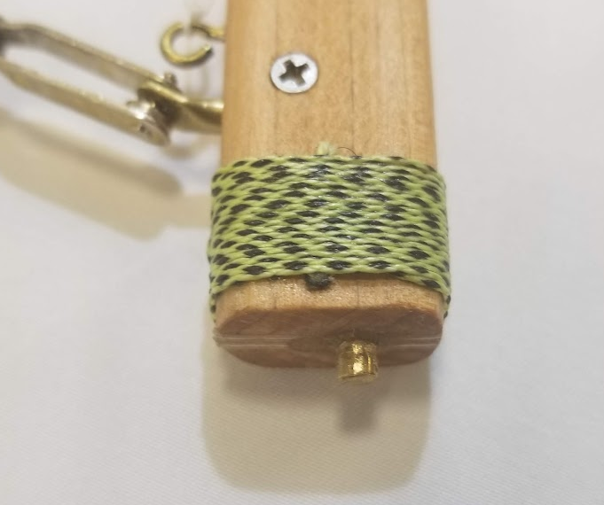
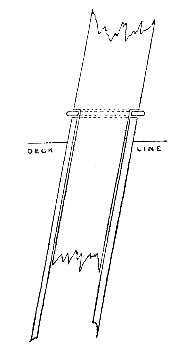
To ship your mast, get a piece of brass tubing of the same diameter as the lower end of the mast, and long enough to reach down to the bottom of your boat and to project 1/2 inch above the deck, and plug up one end of it with a piece of hard wood. Then, having determined the position of your mast in the bottom of the boat, not forgetting to allow for the “rake” (or inclination), fasten a small chock of wood there, and drill a hole in it just large enough to admit the lower end of the brass tube, which should be passed through the deck and fit tightly. Cut away the lower end of your mast, as shown in Fig. 17, and drop it into the tube having previously put a flattened out curtain ring between the collar left on the mast and the tube. The object of this you will see further on.
In this way you obviate any chance of water com- ing in through the mast hole, and have not the nuisance of fumbling about for the said hole in the bottom of the boat when putting the mast in place. An india rubber ring may be put round the tube on the deck, by the by.
The bowsprit must next be shipped. This spar should be made flat where it lies on the deck, and the end should fit into a brass cap or a block of wood screwed to the deck, and a band of metal should pass over it near the stem-post, also screwed to the deck. As the deck is rather thin, you will find it advisable to fix little pieces of wood underneath it in all places where screws are put in. So now you see why the deck should be fastened down last of all.
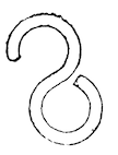
Having got all your spars ready, and the mast, or masts, and bowsprit in place, you can begin the ropes. Get some good whipcord, and see that it consists of three strands. You will want various thicknesses as you will see presently; so get some fairly thick stuff, and then some very fine cord, and some a bit thicker than the latter. Use the thickest for the backstays (Fig. 14). To fix these, screw some few inches abaft the mast on the sides of the deck two “screw eyes,” and fasten two, one on each side, into the mast just below the ferrule, or better still, right through the ferrule, about one- third way up it and into the mast. Now get some brass wire and make a few hooks, as shown in Fig. 18. Take one of these, and having cut the length of your backstay about six inches longer than necessary, splice one end into the eye. If you do not know how to splice, I should advise you to get some one to show you; or if you can’t do that, you must knot all the things instead of splicing, though the latter looks a thousand times neater. Pass the other end of the stay through a double eye, as shown in Fig. 19, and having put another hook on the cord, splice the loose end on to the lower eye of the double eye. Then fix the two hooks, one to the mast and the other to the deck, through the “screw eyes,” and tighten by pushing up the running eye or double one. These double- ended eyes for tightening up the stays or any rope in models that require to be lengthened or shortened a little are termed “slides.”
The next stay to be set up is the bob-stay. This, though, should be made of picture wire, as the ordinary cord would shrink too much with the wet, as it is so often under water, and should be of such a length that by bending the bowsprit down a little you can hook it on to an eye made of wire fastened round the end of the bowsprit, the other end being hooked into an eye screwed into the stem-post a little above the water-line.
These are all the stays that can be fixed up at present, in fact, they are the only ones that are fixed, so to speak, the other two, or one, as the case may be, moving with the fore-sails. But you will see this presently when you have sewn your sails, which is the next job. For these get some jaconet, or very fine long cloth, because you must have them as light as possible. Dip your stuff in boiling water before using it, and let it lie there for some hours, then take it out and stretch it on the floor, nailing it down at each end, not along the selvedge, and in this position let it dry. When you take it up there should not be a crease or pucker in it.

Now carefully mark out the sails on it, taking care that the “after leach” of every sail be along the selvedge and cut them out, leaving about three- quarters of an inch round each sail for hemming. If you can sew yourself, hem the sails up to the line marked,
if not, get some one to do it for you that can, but
in any case it must not be done with a sewing-machine, because, as you would after- wards find out to your cost, the sewing-machine stretches them dreadfully, and they never “stand“ properly, there being always a lot of creases and puckers
round the head and foot of each sail. So never mind the little extra trouble, but sew them by hand.
In cutting out the sails the head should always be rounded, and the foot the same, more especially in lug-sails. The “luff” of the sail should be cut just a trifle hollow.
In larger sails it is necessary to sew tape along all
the edges, over the hemming (except, of course, along the after leach), as the strain on the sails would tend to stretch them materially out of shape.
When your sails are all sewn, iron them over care- fully, and then you can think about “bending” them.
First let us begin with a “gaff-sail,” that is to say, one like a cutter’s or schooner’s mainsail. You have, of course, got your boom and gaff cut to the right length, so to the end of the former fasten a strip of
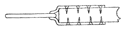
metal, about three-sixteenths of an inch wide, with small screws, as shown in Fig. 20, having previously slipped a curtain ring, bent as shown in Fig. 21, and large enough to fit easily on to the brass tube in the deck, into the bend of the metal strip. Now with some fairly stout wire make some “jaws” to the gaff (Fig. 22), and bind them on with fine binding wire, leaving them open enough to allow of their being “sprung” easily round the mast.
Then sew rings to the luff of the sail large enough to slip easily over the mast, and at distances of about a couple of inches from one another. Slip the ring on the boom over the tube in the deck, put the mast in place (not forgetting the flattened ring), then put the rings on the sail over the mast, and slip the jaws of the gaff on. The gaff, by the bye, should have been laced to the head of the sail, the latter being well stretched. Now fasten the tack of the sail down to the boom by passing a piece of fine whipcord through the strip of metal on the end of it, and through a small hole in the sail, and tying but not too tightly.
For the clew fasten a piece of whipcord to the corner of the sail, and having passed it through a hole near the end of the boom, fasten the loose end to a pin of wire, Fig. 23, and pin to the underside of the boom.
Now fix the throat and peak halliards in the same way as the stays, to “screw eyes” in the gaff, and the mast, tighten them up and your sail will be bent.
To bend a jib or foresail make a boom for it, and at one end of the boom make an eye of wire. Into this hook a stay prepared in the same manner as the backstays, the other end being hooked into the corner of the sail, and with another hook into a screw-eye in the mast through the ferrule. Now fasten the tack of the sail down to the eye on the boom, and with small wire-rings fasten the luff to the stay and haul the clew tight in the same way as the gaff-sail. Now at about two inches from the fore-end of the boom fasten a wire eye round it, and tie this down to its corresponding place on the bowsprit. In this way the leach of the sail is always kept stretched, and the more you tighten up the stay the more you stretch the sail (Fig. 1 4).
For a lugsail you lash the head of the sail to the gaff, and the tack to the fore end of the boom and pull out the clew as before. The mast being stepped in the same way as for a gaff-sail you have simply to fasten a ring to the boom at about one-third from the fore end and the same on the gaff, and pass the former over the tube in the deck and the latter over the mast. The flattened ring will hold the boom down, and allow it at the same time to turn easily. The gaff should be tightened up with a “slide” to a screw eye a little way above it in the mast.
Topsails are swung as lugsails, the clew being fixed to the end of the gaff and the tack pinned to
the mast. I have not said anything about the “sheet” yet. This should be fixed as near the end of the boom as practicable, and made to work through a ring running on a “horse” and then pinned to the deck. Most pin the sheet to the boom, but it weakens the boom very much, and, besides, it is much easier to get at the deck.
A “horse” is merely a piece of stout wire bent in the form of an arch, and screwed across the deck, the one for the mainsail being as near the end of the counter as practicable, and the one for the foresail between the mast and end of the bowsprit.
I think you have enough instructions here for rigging a model thoroughly, and I will, just to finish my papers, give you a hint or two for sailing.
When you first try her, make her go to windward, i. e., in the direction from which the wind comes. For this pull the sails in to a small angle with the centre line of the deck and let her go. If she comes up into the wind and shakes, you must either tighten in the head sheet or “loose the after sheet,” if she falls away from the wind do vice versa.
For “reaching,” that is with the wind at right angles to the direction in which you want the boat to go, let all the sails out to about 45 deg. and then treat her the same, if she comes up, or falls off, as for going to windward.
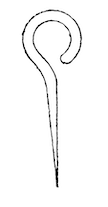
For a “quartering” wind let the sails out at rather more of an angle than for “reaching,” and for “running” put on a rudder (Fig. 24), and let out the mainsail if a cutter on one side at right angles to the boat, and the mainsail on one side and the mizzen on the other if a schooner or lugger, and flatten the head sails down well and let her go.
Last, but not least, comes the rudder. As you will have seen from the above, I only use one, and that is running, and this one cannot be too heavy, in moderation of course. It is made as follows:
Take a strip of wood about 1 inch shorter than the stern-post, and of the same thickness and about 1 inch wide. Screw into it two screws, (Fig. 24), and then having made a mould to something of the shape place this piece of wood in it, and pour lead into the other part of the mould, so that the melted lead may run round the screws and against the wood. Trim this up afterwards nicely and you will have your rudder, which should be fixed by two pieces of wire bent at right angles and driven into the wooden part of it, dropping into two screw eyes in the sternpost.
One little thing I should like to mention before I bid adieu to my readers, and that is to put a strip of brass all along the bottom of the boat; they will find this saves the paint being scratched, and prevents the lead getting knocked about.
I hope the outcome of these papers will afford many hours’ amusement to some readers.
Arthur C. Hide (1885)