Article and photos, John Henderson
Those of us who sail vintage R/C boats do so because we either enjoy the process of scratch building from plans or value the skills involved in scratch building. If we elect to build scale models of full-sized boats, then we certainly want the result to look realistic, but we also insist that it sail well. These two goals have more or less equal importance, but they can conflict, and so we must address the trade-offs. We recognize that R/C boats that were conceived without reference to any full-size vessel may have some advantages for sailing at small sizes, but their appearance can be jarring to those of us used to “real” boats – they might be too narrow, or too deep, or the aspect ratios of the sails may be exaggerated to the point of caricature.
That said, the requirement that the models actually sail well imposes some practical limitations. It is a premise of these articles that scale details and even exactitude in matters such as rig will be sacrificed in the interest of ruggedness, stability, and management with 2 or 3 (maybe 4) channels of radio control. We may think about eliminating or simplifying some deck details (winches, air scoops) if their presence would tend to snag sheets or other control lines. The hoped-for result is a model that looks realistic from a “stand-off” distance (OK, maybe “stand-way-off”), that will sail in a reasonable range of conditions, that can be transported with no more care than other R/C models, and that can be rigged at the launch site with no more than the usual care.
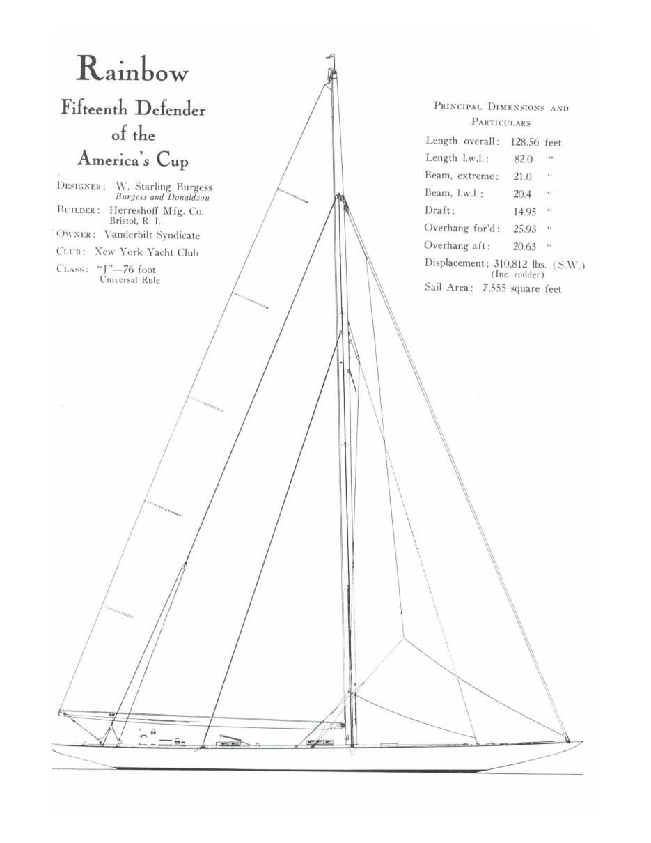
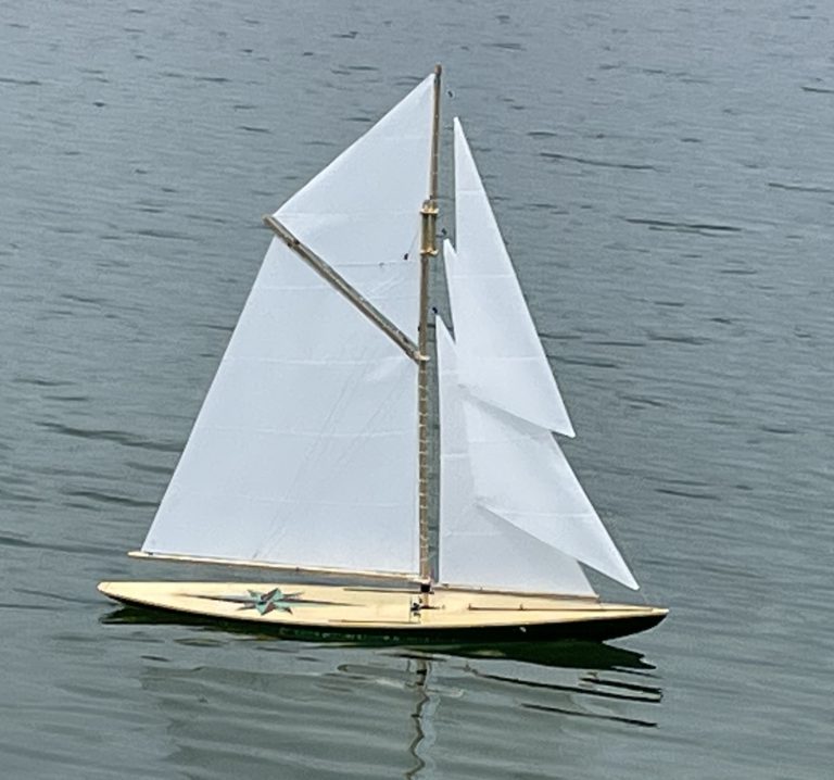
As an example, and to give some specificity to this series of articles, I will use the building of a model of the J-Class yacht Rainbow. Plans for this particular boat are available: for example, in much-reduced form in the book Enterprise to Endeavor by Ian Dear; in 1:16 scale through the AMYA J Class. The latter choice produces a magnificent model, which is about 8 ft long and weighs in the neighborhood of 75 lb. Magnificent it may be, but, at least for me, it is not a practical size or weight for the kind of broadly useful model I want to build and own. Therefore, the Rainbow model whose design choices we will work through in these articles, will be a bit smaller than 1:23 scale, which, as we will see, brings the length to about 5 ft 9 in and the weight to around 25 lb. It fits into my car easily, and I can carry it to the water by myself.
In future articles, we will use the lines drawings to calculate accurately the displacement, center of buoyancy, ballast, etc., but at this point we just want some quick calculations to get us into the size ballpark. The first requirement is overall length, which is generally constrained by the transporting car or the storage space or the building space. Pick the length you want and divide it into the length of the full-scale prototype. In our example, this gives the 1:23 scale in the paragraph above, meaning that the model is 1/23 as long as the prototype. It also means that every linear dimension (e.g., length, beam, draft, mast height, boom length) is reduced by a factor of 23.
Using the scale factor, we can do a quick (and surprisingly accurate) estimate of the model’s weight. We know that all boats must displace a volume of water whose weight matches the weight of the boat (so sayeth Archimedes). That volume of water is the volume of the boat below the waterline. All volume calculations are based on the product (i.e., multiplication) of 3 linear dimensions – length, width (beam in our case), and height (draft in our case). Therefore, if each of the linear dimensions is reduced by a factor of 23, then the volume is reduced by a factor of 23 to the 3rd power (i.e., 23 cubed). Yes, I know that the underwater shape of a boat is complex, but that does not change the cubing function. So – some simple arithmetic:
- 233 = 23 x 23 x 23 = 12,167
- The displacement of the prototype Rainbow was 310,812 lb (according to page 97 of Enterprise to Endeavor and Fig. 1 ).
- And so the expected displacement (weight) of our model is 310,812 / 12,167 = 25.5 lb.
This is a weight that I can manage.
Key point: The expected weight of the model is the prototype’s weight divided by the cube of the scale factor.
Note that this displacement (or weight) calculation is not derived from an estimate of the weight of
the hull and its components and equipment. Rather, it is a calculation of what the model must weigh in order to float on its lines. It is derived from a volume calculation of the portion of the hull below the waterline. Since a scale model must float on its designed waterline, this tells us that the weight of a 1:23 scale Rainbow, including hull, ballast, rigging, and radio gear, must come to about 25.5 lb.
We can use a similar approach to estimate the model’s sail area. The linear dimensions of the mast and boom are each reduced by the scale factor, so the prototype’s sail area is reduced by the square of the scale factor. Applying this to our example 1:23 Rainbow, again referring to Fig. 1:
- 232 = 529
- The sail area of the prototype Rainbow was 7,555 ft2.
- And so the expected sail area of our model is 7,555 /529 = 14.4 ft2 = 2,074 in2.
Putting that much sail area on a model of this size should give us pause, especially if we note that, for example, an EC-12 R/C model, whose waterline length, beam, and displacement are quite similar to our 1:23 J-Class model, has a sail area in the range of 1200-1300 in2. In my own (limited but non-zero) experience, a scale-sized rig (2,074 in2) on a scale hull might work spectacularly well in light air, but it is probably not suitable for the kind of “all-weather” model that is our goal. E.W. Hobbs, in his book Model Sailing Yachts, makes a similar point on page 35. To make the model practical for a wider range of conditions we must either: 1) make the model more stable with a deeper keel (perhaps even an added non-scale fin- and-bulb) or 2) reduce the sail area. In the example model developed for this series of articles, I will opt for a “judicious” combination of these two options.
To generalize the situation for practical sailing scale models: We acknowledge that a scale-sized rig makes for a proper-looking scale model, but it generally (or at least very often) leads to a model that is over-canvassed for actual practical sailing. In planning the sail area and rigging, the calculated scale sail area must be compared with the sail areas of practical models of similar size and weight. In most cases, and especially for scale models of racing yachts, I think it is wise to reduce the sail area below the proper scale dimensions. For example, if you made the mast and boom each 90% of their proper scale size, then the sail area would be reduced to 81%, which might still be too aggressive. I believe that this sail area compromise is fundamental to making scale models that sail well. Perhaps the compromise would sound better if we called it a “B Rig”.
I also believe that it is common practice among R/C scale modelers to make the keels a bit deeper than scale. For example, the AMYA J Class permits keels 2 in deeper than proper scale, which seems a good compromise. In other scale models, some folks add a fin-and-bulb that is inserted for sailing and removed for display, which is another good compromise at the expense of some added complexity at the launch site.
We can debate the causes for this scaling problem. I suggest that it is partly because air density and wind speed are not scaled, but it is also true that bigger boats are simply more stable and survive tough conditions better than smaller boats – look at some reports of full-size ocean racing disasters (e.g., the famous Fastnet). Although there is a bit of hand waving in this next argument, we might also note that the heeling forces are related to the sail area, which was reduced by the square of the scale factor, while the stability is related to the displacement, which was reduced by the cube.
Even if such departures from scale make you cringe, they offer another advantage that might make you cringe even more. Most “early” race boats (think America’s Cup before and including the J Class) had running backstays that were required either by the gaff rig or the long booms on their Marconi sails. Running backstays are a considerable complexity for an R/C model, and reducing the rig size judiciously may enable use of a (non-scale) permanent backstay. Just sayin’.
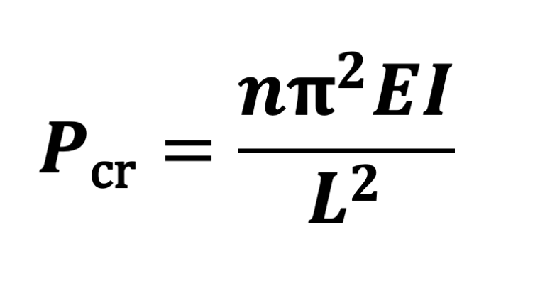
While the boat size and weight and the sail area and mast height are the most important initial parameters to plan what we will build, there is at least one more interesting calculation that we can perform to evaluate our potential project. That is the ratio of sail area to displacement, which is (sort of) to a boat what the ratio of horsepower to weight is to a car. The equation is:
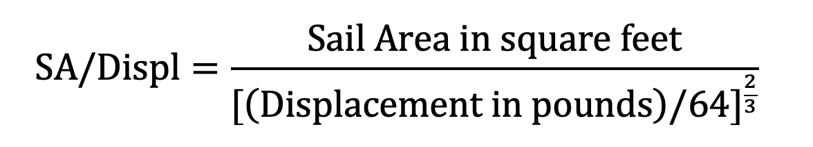
Note that the units are square feet and pounds. The factor of 64 is the density of salt water in pounds per cubic foot. Note also that the denominator of the equation must be raised to the 2/3 power, which means you will probably need a calculator more advanced than the one needed to balance your checkbook (or you can search on-line for “Sail area to displacement ratio calculator” and just plug in the numbers). Note also that the ratio is dimensionless – the dimensions of both the numerator and denominator are square feet. A consequence is that the SA/Displ does not depend on boat size, and so the full-size prototype will have the same SA/Displ as our model.
The SA/Displ is, in some sense, a measure of the “liveliness” or “sportiness” of the boat. While this has some correlation with the inherent stability of the design, we should not conclude that our model will have the same stability as the prototype. We have already discussed the stability issues related to scaling. I think the best use of SA/Displ for our purposes is to compare different models. We can compute the ratio for other models in the same size range as the one we are considering, and we know or can learn their performance characteristics. So computing the ratio for our model during the planning stages gives us more confidence that our model will be practical.
In case it is not already clear, a purpose of these articles is to enable calculation of model characteristics in advance of building. We will not shape a hull, put it into a swimming pool and add ballast until it floats on its lines and only then learn the weight. We will try to make reasonable rig size adjustments and plan the location of the resulting sail plan to try to get the helm balance right as built (OK, I confess that this can be tricky even for full- size and fully analyzed designs, but we’ll try to get very close). We will try to plan the location of the weight of R/C gear by first calculating the fore-aft center of buoyancy. In short, we’ll try to work out an actual design. I think this saves extra work after construction is well along, and, frankly, it makes us feel like we know what we are doing.
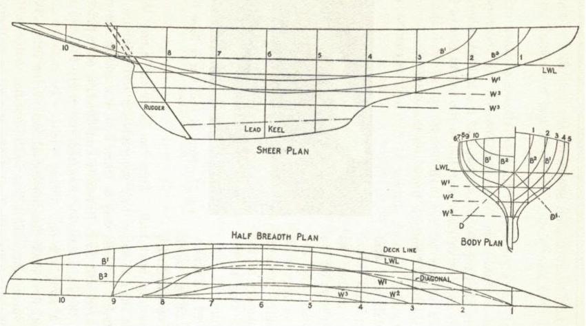
The basis for all of these calculations is the lines drawing. Therefore, we will spend a little effort to reach a common understanding of the basics of this plan. Fig. 2 shows a simplified lines drawing of a generic vintage-type model boat, which I have taken from page 80 of the book Model Sailing Boats by E.W. Hobbs. Drawings for prototype-size boats would have many more lines – a plan like this, with relatively few lines drawn, might be suited for making a carved model from a solid block or a bread-and-butter glued block, but you would probably need more sections to build an accurate plank-on-frame model. I chose this simplified drawing to clarify the key elements.
A lines drawing consists of three parts:
- a profile view (called the “Sheer Plan” in Fig 2);
- a set of sections (called the “Body Plan” in Fig. 2) – note that the half-sections for the forward half of the hull are shown on the right side, and the half-sections for the aft half are on the left;
- a half-breadth plan.
The profile view, as its name implies, shows the side view of the hull, emphasizing the shape of the keel line and the sheer line (the edge of the deck). The numbered vertical lines are the fore-aft locations of each of the sections, whose shape is revealed in the sections view. The main horizontal line is the designed waterline, identified as LWL (load waterline) on the drawing. The horizontal lines parallel to the LWL, numbered W1 , W2, etc. (which are also shown on the sections drawing as horizontal lines) locate the curved lines in the half-breadth plan, and they show the shape of the underbody of the boat. These waterlines are like the edges of the slabs in a bread-and-butter model – in fact, if the wooden layers were sized appropriately, they would define the shape of each layer.
For plank-on-frame (or plank-on-bulkhead) models, we shape each frame (bulkhead) based on the sections drawings. Note that, unless specifically stated otherwise, these sections show the outside of the planking, as necessary because these sections are used to calculate the displacement of the boat, which, as we have seen, is the underwater volume and necessarily includes the thickness of the planking. Therefore, when we use these drawn sections to shape our frames (bulkheads), we must reduce the size of the frame by the thickness of the planking we have chosen.
The profile view shows us the spacing of the sections as we will set them up on the building board. It is the usual practice to make the sections equally spaced, since this enables calculation of the underbody volume by a method (Simpson’s Rule) that we will describe in a future article. Simpson’s Rule also requires an even number of sections, and this is the usual design practice. More sections create more accuracy in the volume calculation, but it may not be necessary in model building to create a frame at each section. It may, however, be wise to make more closely spaced “extra” frames at places where the hull shape changes rapidly – e.g., below the waterline just forward of the rudder – to enable the planking to be bent accurately.
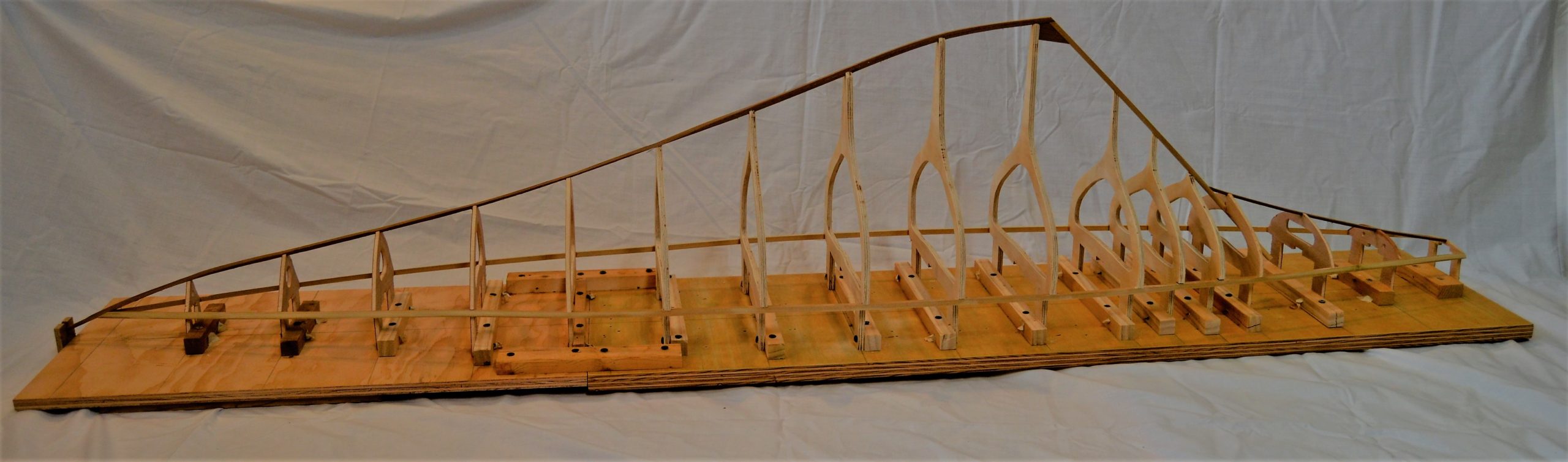
A drawing of each section, reduced by the planking thickness, defines the shape of each frame. Trace each section onto the frame material and cut. I think it is convenient to also shape the deck camber by making the deck beam part of each frame – i.e., by making each frame a “ring”. See the photo in Fig 3. This deck camber may or may not be shown in the lines drawings (it is not shown in Fig. 2); if not, then you must draw a reasonable deck camber that is consistent on all frames.
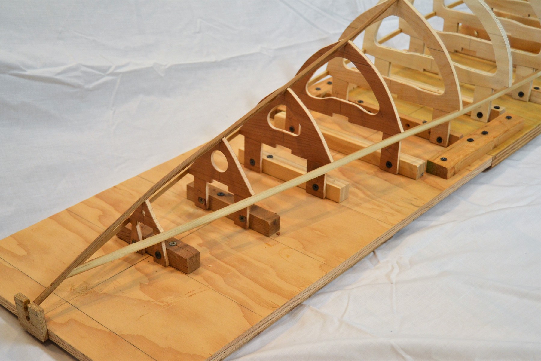
I think it is easiest to plank the boat upside down on the building board. To do this, not only must each frame be shaped, but the height above the building board must be established for each frame – this is how we create the proper curve in the sheer profile. To do this, draw a reference line some arbitrary distance above the sections drawing and add “legs” to each frame to reach this line. Make the legs long enough to allow you to reach under the sections to retrieve parts that you drop inside the hull when it is mostly planked; we won’t talk about why I find this point so important.
Fig. 3 shows sections erected upside down on the building board. Note also the “extra” frames in the area just forward of the rudder location. Fig. 4 shows how the “legs” establish the height of each section above the building board, creating the curve of the sheer.
The half breadth plan can be used to bevel the frames and keel before they are mounted on the building board – and I think shaping before mounting is more convenient. Examine the half breadth plan where each section (vertical lines) crosses the waterlines (LWL, W1, W2, etc.) and the keel (straight horizontal line at the base). If you add lines showing the actual thickness of the sections and the keel, the dimensions of the forward and aft faces (where they cross the waterlines) of each section will be slightly different, depending on the angle of the waterline at that section.
The observation in the previous paragraph also reveals a necessary caution about mounting the frames. The section line on the drawing defines the bigger face of each section. The bigger face is almost always toward the center of the boat, and it is this bigger face that must be located at the defined section spacing (not, for example, the center of the frame).
The other lines on the lines drawings are buttocks (B1 , B2) and diagonals (D1, D2). They are useful in designing to reveal the way water runs along the bottom when upright or heeled, but we can pay them less heed when building a scale model of a boat that has already been designed, except perhaps, as aids to fairing the bottom.
There may be times when the only design information is a Table of Offsets, not an actual set of drawings. The Offsets are a numerical tabulation of the drawing dimensions – e.g., the width of each section at each waterline, the height of the sheer at each section, the section and waterline spacings, etc.
From such a Table of Offsets, you can reconstruct the lines drawings by plotting the defined points and then connecting them with fair lines. The “fairness” of the lines so created must be checked for consistency among all three views. This is not a trivial task.
After going through all these exercises, I think we have the basis for a sound choice of model and size. We have also gained a lot of familiarity with our planned model, well beyond simple appearance. In future articles in this planned series, we will discuss “normal” changes to a scale model to make it more practical (e.g., deeper keel, bigger rudder, rig), and we will make a more detailed calculation of displacement that includes these changes. We will find the lateral center of buoyancy, which will help us get the ballast in the right place. We will make the best estimate that we can of the center of effort of both the hull and the sail plan, to try to put the mast in the right place (if we have reduced the sail plan, the center of effort of the rig of our model may not match that of the prototype). And then we will go through the process of actually building the model.