Article and all photos by John Henderson
We all probably have a love/hate relationship with our batteries. We need them, we have our favorites, and they bring on bad language when they fail. Before we assign blame to old battery packs, to different manufacturers, or to different battery types, let’s be sure we are using them appropriately and caring for them properly.
As R/C modelers, we are familiar with at least four battery chemistries: alkaline, nickel–metal hydride (NiMH), nickel–cadmium (NiCd), and lithium-based batteries (lithium ion, lithium polymer, lithium iron). I am not going to discuss NiCd. Some decades back it was the only rechargeable technology available to us, but I believe that the other rechargeable choices available now are superior in terms of energy density (the amount of charge stored per weight) and, perhaps especially, the lack of the “memory” effect that is associated with NiCd (repeated partial discharges result in loss of capacity).
In what follows, I will try to present the pros, cons, and general utility of the different battery technologies for R/C model applications.
Alkaline
These are easily available everywhere and relatively inexpensive, at least for initial purchase. They are not rechargeable, however, so costs go up if you discharge them quickly or change them frequently “just in case”. When not being used, they hold their charge quite well, so they are good for spur-of-the-moment sailing excursions. Alkaline battery cells each put out a nominal 1.5 volts (V), so four of them stacked in the usual series configuration make 6 V, which seems to be the design point for most receivers and analog servos. Digital servos, although usually capable of operating at higher voltages, can be used at 6V, but their typically higher current requirements may stress alkaline battery capabilities, as will be discussed below.
Alkaline batteries have at least one serious drawback—they are not good for high current applications, such as swing-arm sail controls. Restating this more technically, they can be considered to have high internal resistance.
Here is what that means: All of us have probably seen somewhere the fundamental equation that relates voltage, current, and resistance:
Voltage = Current x Resistance
Resistance inside the battery thus reduces the voltage available at the battery output terminals.
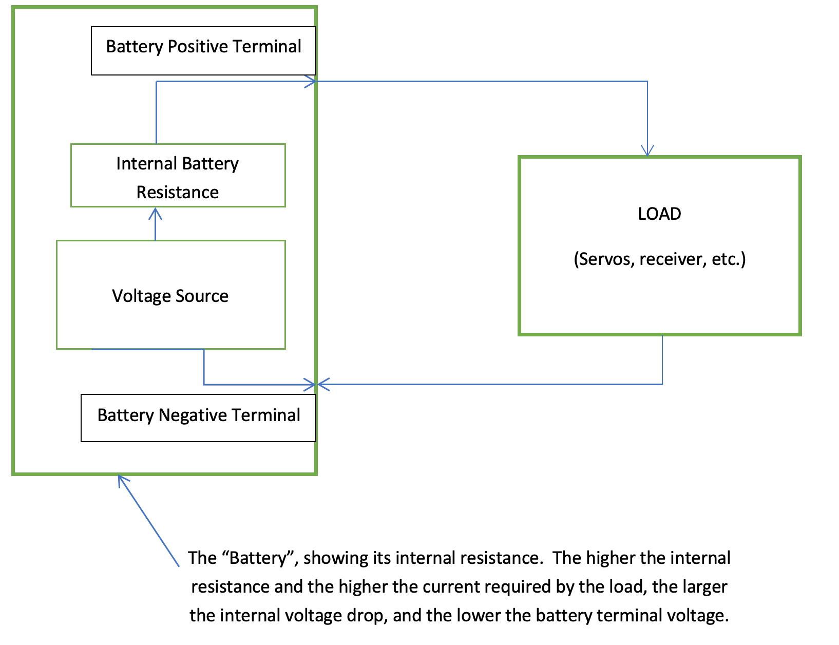
When we use an alkaline battery to power a large servo, the servo’s high current must pass through the internal resistance, so the output voltage is reduced. This is much more than an academic observation. In the usual case where four alkaline batteries would be connected in series to create a 6-V supply, the output voltage might be reduced to a level where the receiver becomes erratic, especially if the batteries are not fresh. Do your controls get “funny” on a windy day? Do you have better control downwind than upwind? If you are using alkaline batteries, they might be the culprit.
Your experience may vary for a variety of reasons (friction in the sail controls or initial stability of the model), but I think sail areas greater than about 600 in2 should have batteries with technologies other than alkaline.
Nickel–Metal Hydride (NiMH)
NiMH batteries are capable of supplying much higher current without significant voltage drop, so they give more satisfactory results in situations of high current draw. I have used them in large-ish scale or vintage models (5–6 ft) with at least 1600 in2 of sail area. In these cases, I used two sail control swing-arm servos. (Example: In a schooner, I might put the jib(s) and foresail on one servo and the mainsail on a second servo.) I confess that I do not use these models in high winds, but that reflects my own cowardice, not a battery limitation. NiMH batteries can also power the Vintage R/C Skipjack class at ~1300 in2 of sail area. A swing- arm servo without added gearing in this application may not be powerful enough in strong winds, but that is a servo problem, not a battery problem. In these models, I think a 2000-mAhr pack is sufficient for about 2–3 h of sailing, but an all-day race series in strong winds would probably require charging or exchange of batteries.
NiMH battery cells have a nominal voltage of about 1.2 V. Therefore, a pack that generates 6 V must have five cells. Using only a four-cell NiMH pack at 4.8 V might be possible, but it is usually not recommended. If you are fanatical about weight, the five-cell NiMH pack compared with four alkaline cells might cause angst.
There are no special charging anxieties with NiMH, although you should use a charger specific to this technology. A smart charger will taper down to a trickle when the battery is fully charged, but it is probably not a good idea to leave batteries on charge longer than necessary. Some chargers indicate how many milliamp-hours (mAhr) they put into the battery to bring it to full charge, and this is a useful indication of how close you came to depleting the battery in its last outing.
Lithium-Based Batteries
Two types of lithium batteries are available to us for R/C applications: lithium-ion polymer batteries (LiPo), and lithium iron phosphate batteries (LiFePO4). These batteries have even higher energy density (charge stored per weight) than NiMH batteries.
Lithium Polymer Batteries (LiPo)
The nominal LiPo cell voltage is about 3.7 V. This means that a single cell is inadequate to power our usual receivers and servos. A two-cell LiPo pack generates about 7.4 V, which may be too much for the usual receivers and analog servos. The problem is easily solved for receivers and small servos by using a Battery Eliminator Circuit (see below) to reduce the 7.4 V (or other supply voltage) to whatever voltage is comfortable for the receiver (usually about 6 V). Because the whole purpose of using a high capacity battery is to power the sail servo, you must make sure that your servo will indeed handle a 7.4-V supply if you use LiPos. Most digital servos meet this specification, but analog servos rarely do. Note that high-current analog servos must not be powered from the 6-V output of a BEC, since BECs are almost always incapable of supplying the necessary current.
There have been many spectacular fires resulting from misuse of lithium batteries during charging or discharging. Lithium burns at an extremely high temperature, and generally the fire cannot be extinguished with water. These batteries should be charged only with a specific LiPo charger. Multiple cell battery packs (as would be required to get voltages higher than 3.7 V) desirably allow the charger to monitor individual cells during the charging process.
In my opinion, LiPo batteries are well suited for R/C car and go-fast motorboats, whose motors are generally designed around 7-V or higher supplies (e.g., six-cell NiMH or two- or more-cell LiPos) and whose speed controllers generally include a BEC function to power the receiver and (low current) rudder servo. I am not sure that LiPo is necessary for R/C sailboats with swing-arm servos, especially for relatively large ones like the typical Vintage model where a few extra ounces for NiMH is inconsequential. Digital servos and analog sail control servos with geared drives may have motors that benefit from larger voltages, for which LiPos may be appropriate. The servo that drives the switches on these sail controllers may need a 6-V source for power, possibly provided by the BEC voltage regulator.
Lithium Iron Batteries (LiFePO4)
The nominal LiFePO4 cell voltage is usually given as 3.3 V. Therefore, a two-cell pack provides a nominal 6.6 V, which is somewhat above the stated 6 V specifications for standard receivers and analog servos. LiFePO4 battery manufacturers say that this 6.6-V source “typically does not require a regulator.” (A voltage “regulator” is a more technical term for a BEC.) They are probably right, but I think that caution is warranted for any operation outside specified ranges. Specifically for our application, I do not know the consequences for operating sail servos (with high load and therefore high current) at a higher-than-specified supply voltage. On the positive side, LiFePO4 batteries are claimed to be safer than LiPo batteries.
How It All Gets Connected
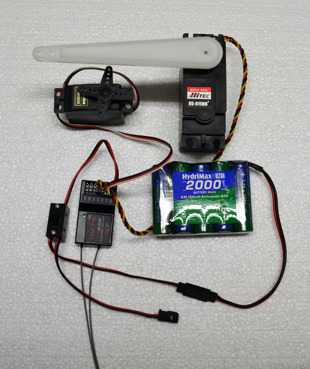
Fig. 2 shows the radio parts connected as they would be installed in a two-channel boat. I have used exactly this setup in boats up to about Skipjack 48 Class size (~4 ft LOD, ~1300 in2 of sail, 22.5 lb displacement). For larger boats, I would use a second, separate sail servo for the jib(s), but the battery pack would be the same. This example is a simple and relatively low-cost 6-V system. The particular product brands are matters of personal preference and part availability. The salient points in the figure are:
- Digital transmitter/receiver modulation, which eliminates the crystal frequency and interference issues of the past. (Note that digital modulation, which virtually all new radio transmitter/receivers use, is not the same as a digital servo.)
- 6-V, 2000-mAhr battery pack.
- Switch with charging leads (the unattached pigtail connector at the bottom center of the picture).
- Large sail control servo, operating at 6 V (this could be a winch or drum if preferred).
- Smaller rudder servo.
A key point is that all of this operates directly from a 6-V source. The battery and both servos can be plugged directly into the receiver connector terminal row, and there is no need for a separate connection to the sail servo, even though it draws high current. It can plug directly into the receiver.
The Battery Eliminator Circuit (BEC)
If your sail control (or any other component, such as a motor) requires a voltage greater than 6 V and you want to power everything from a larger battery, then you must use a Battery Eliminator Circuit. The function of a BEC is to reduce the voltage and supply the reduced voltage to the receiver and any servos that operate at 6 V and low current (e.g., the rudder servo). Most BECs will not handle enough current to power a swing-arm servo controlling any significant sail area.
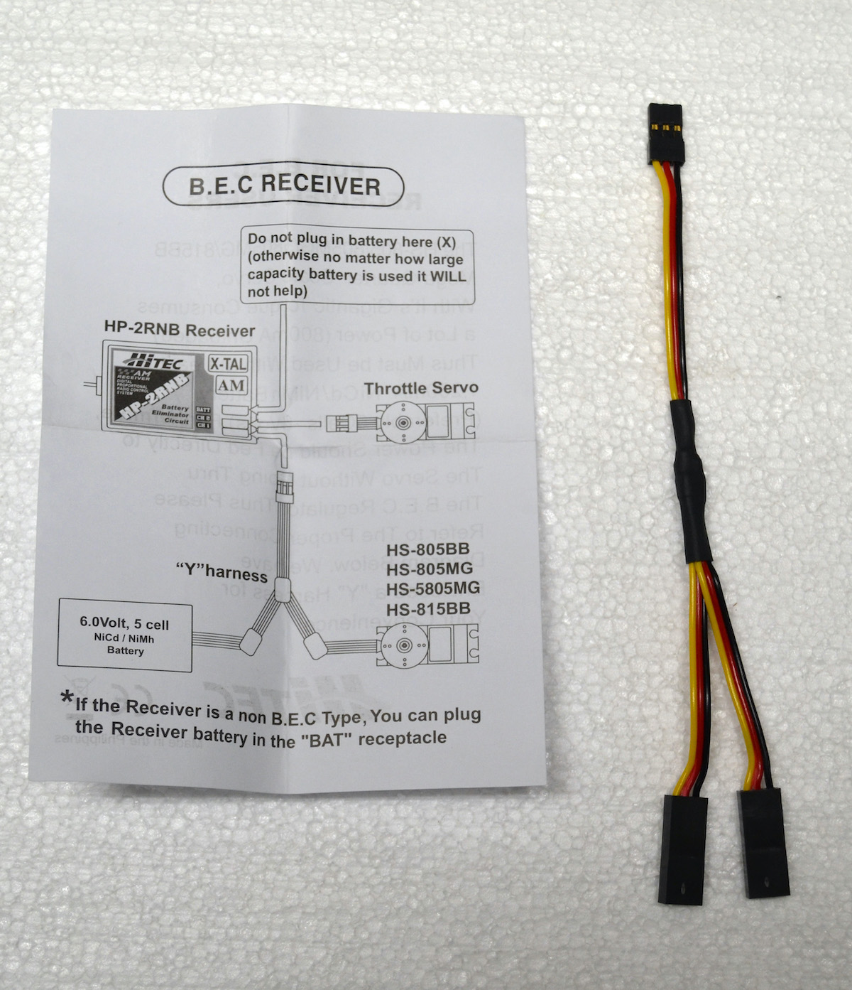
Fig. 3 shows one manufacturer’s approach to by-passing a BEC with a “Y” harness to serve a high current (sail control) servo. Note that this particular instruction sheet assumes that a 6-V battery is available, and the instructions are intended only to caution against plugging that 6-V source into the “normal” BEC power connection. The arrangement shown gets the 6-V power to the receiver’s power “bus” via the sail control servo’s plug. Because there is no voltage greater than 6 V, the BEC circuit is not needed. This is different from the more usual BEC application, where the BEC serves as a voltage regulator to convert a higher voltage source (e.g., 7.4 V) down to 6 V for the receiver and small servos.
Digital Servos
For remote control, the radio’s digital signal is demodulated into an analog pulse width that is supplied to either an analog or digital servo. An analog servo controls the arm position with a feedback loop that rotates the arm until an internal circuit generates a pulse to match the received analog control waveform. A digital servo turns the analog pulse width into a digital number, which then causes the arm to be positioned to match it.
The wiring situation is more complicated for installations with digital servos that operate at voltages higher than 6 V. In these cases, the digital servo should be supplied directly from the higher voltage source. The higher supply voltage would also go to the input to the BEC. The servo must get its control signal from the appropriate channel connection on the receiver, but the servo must not be connected to the 6-V power bus on the receiver. The power lead (usually a red wire) between the receiver’s power bus and the servo must be severed so that the servo’s higher voltage does not get to the 6-V bus on the receiver. The BEC could either be a separate device or built into the receiver, so follow instructions supplied with your particular device.
A Moderately Demanding Application
To make the case that a reasonably large model can be managed with a thought-out but modest battery installation, I present an example—chosen, necessarily, from my own small fleet of vintage models. It is a semi-scale model of the America’s Cup gaff-rigged cutter Columbia, the defender in 1899 and 1901 (Fig. 4). The model dimensions are:
- LOD: 60 in
- LOA (including bowsprit and main boom): ~6.5 ft
- LWL: 40 in
- Sail area: 2200 in2
- Weight: ~19 lb, including 11 lb of lead ballast
- Scale: approximately 1:26 (carefully chosen to fit inside my compact SUV)
Compared with proper scale size, all linear dimensions of the rig were reduced to 90%, meaning that the sail area was reduced to 81% of scale. I did this to get a Sail Area/Displacement ratio that was somewhere near reasonable (well, OK, close enough to see “reasonable” if you used binoculars in good light). Also, the draft was increased by about 1.75 in. See “Building Scale Models that Sail” for details on these calculations.
As is evident from the above specifications, this model has a pretty large rig on a fairly light hull, and there is no added fin-and-bulb keel to improve stability. As expected, the model does well in light air and gets overpowered in heavier air unless the topsail is removed, which can be done easily. From what I have read, the prototype exhibited similar behavior.
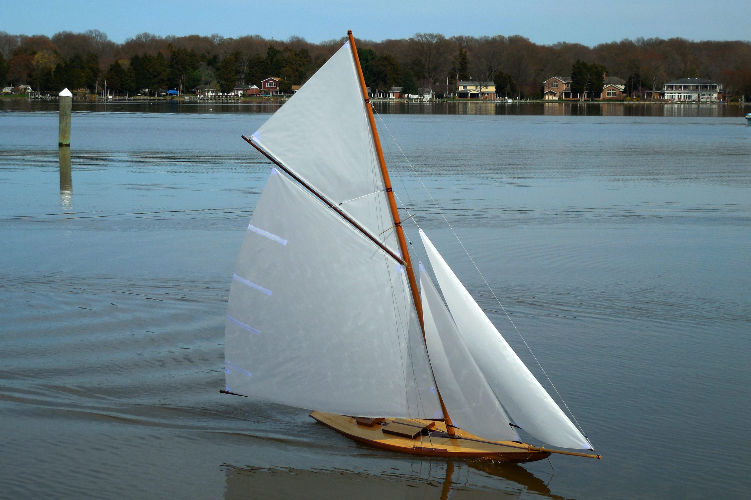
Of interest to an essay on battery demands is the fact that the boat, being narrow, has fairly low initial stability; it doesn’t take much wind to generate moderate angles of heel. Heeling the boat projects less sail area to the wind, which reduces the demands on the servos and battery. See Fig. 4 for an indication of the size of the rig and the initial stability of the hull.
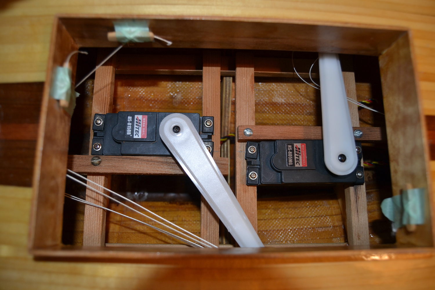
The servo installation is shown in Fig. 5, where the bow of the boat is to the left. Both jibs are controlled by the servo on the left. The main is controlled by the servo on the right. Both swing arms are rigged for a 2:1 mechanical “disadvantage” (i.e., they pull in twice as much line as the distance that the arm moves). This two-servo arrangement allows good control of the directional balance of the boat, can be an aid in tacking, and makes the loads manageable with swing-arm servos.
The battery is a five-cell, 2000-mAhr NiMH pack. I have sailed the boat for 1.5–2 h in its maximum “comfortable” winds (probably not much more than 10 knots) and still had at least a third of the battery capacity remaining. I think this is reasonable, but others may expect more. I offer this data for reference in your own planning.