by Earl Boebert
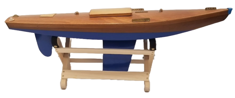
When Dave brought the existence of this boat to my attention in a series of emails I knew that she was so important that her lines had to be in the historical record.
Traditional Methods
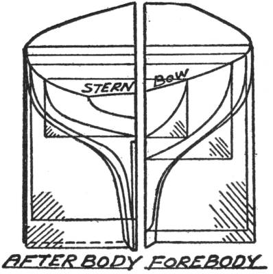
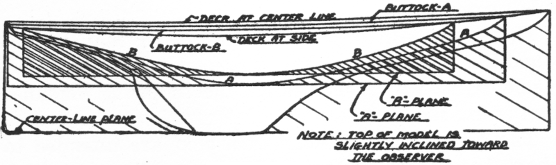
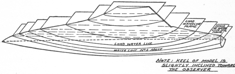
A hull is traditionally depicted by three drawings: a profile, a plan view, and a body plan. Each of these shows interior planes: the profile shows the buttocks, the plan view shows the waterlines and the body plan shows the sections. These are depicted in the illustrations that follow, which are from Thomas Moore’s Build a Winning Model Yacht.
The process generally begins by taking off the sections, and then developing the other curves by a process called lofting.
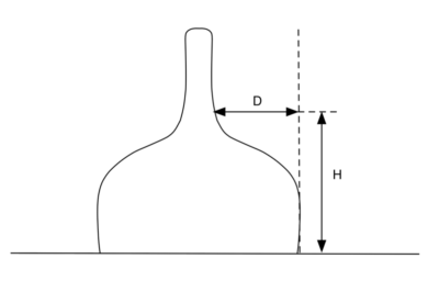
Measuring the sections of an existing by the traditional method is a tedious process that require specialized equipment. Basically, at each section interval, one must obtain a series of measurements called offsets, as shown in the diagram below:
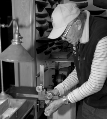
This method also requires some measuring apparatus that touches the hull at each point of measurement. The most famous of such devices was used by Nathanael Herreshoff, who designed in three dimensions by carving half-hulls and then took offsets which were then scaled up to produce the full size boat.
The operation of the device is shown in the photo. The upper knob moves the horizontal bare vertically and provides a readout of the dimension H in our diagram. The lower knob moves the bar back and forth and provides a readout of the dimension D.
Besides requiring special equipment, the traditional method involves touching the hull being measured at multiple points, which may not be desirable for an old and important hull.
A Modern Method
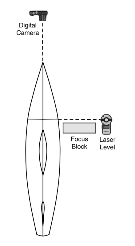
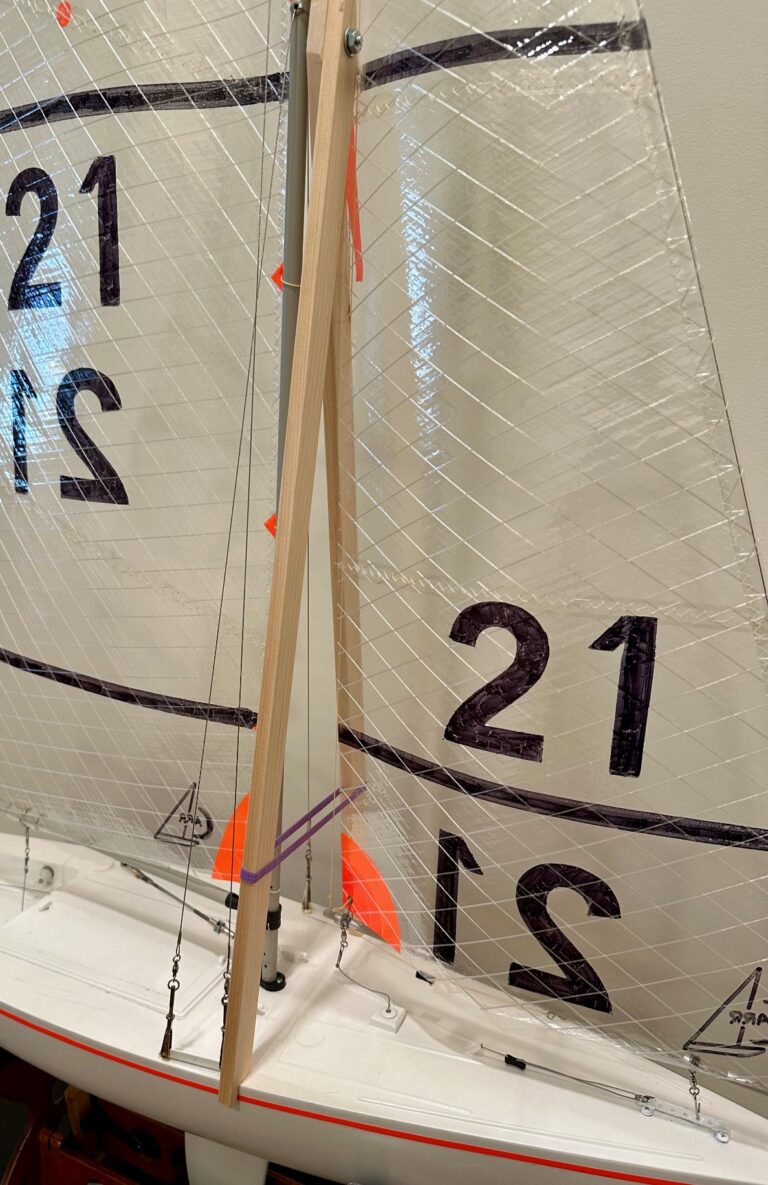
I had been experimenting with the application of modern digital technology to this problem for some time, and the opportunity posed by Dave Crawford’s boat got me going again. After some further trials I put together a set of instructions that Dave followed with great success. The required equipment is a digital camera, a laser level, and a vector graphics computer program. The process requires blocking up the boat so the waterline is level, setting the laser level to throw a vertical line on the hull, and then photographing the line. A focus block is placed just behind the laser line to “fool” the autofocus of the camera into focusing at the proper point.
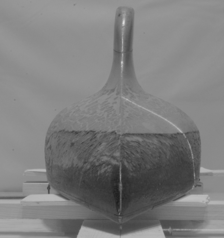
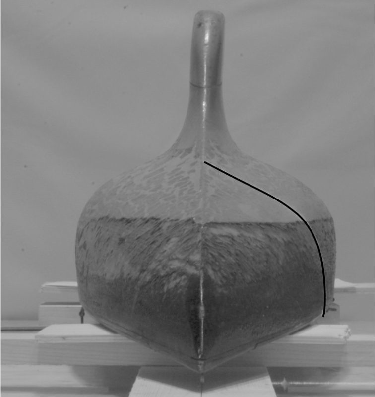
The resulting photograph will look like this:
The next task is to convert the projected laser line to something that can be used in a drawing. To do this we need a vector drawing program. I use EazyDraw for the Mac; there are several similar programs for Windows. The program should be able to handle “layers” and be able to smooth polylines into Bezier curves. The first step in conversion is to draw a polyline in a layer above that of the photo:
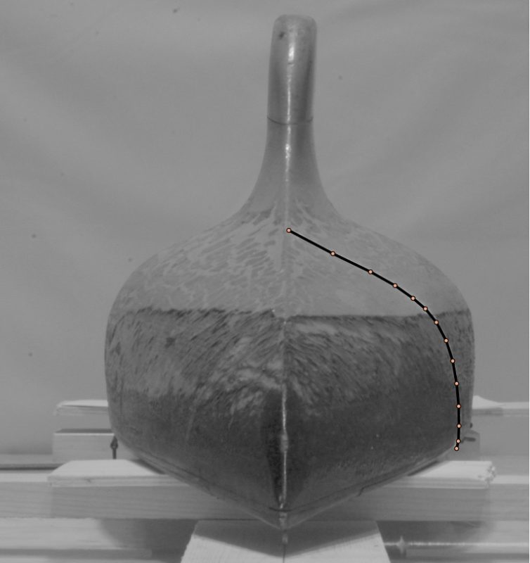
Then the curve is smoothed:
It can then be copied and pasted into the working drawing. Since we are working with a fair hull containing smooth transition from section we do not have to take a photograph at each desired section point. Rather, we can capture just three master sections: the midships master section, which defines the basic hull shape, the forebody master section, which defines the transition from the bow to midships, and the afterbody master section, which defines the transition from midships to the stem. The sections in between then can be interpolated by the lofting process.
The midships master section is usually at the point of maximum beam. The other two sections take a bit of judgement to find, but they will be roughly halfway between midships and the end of the boat.
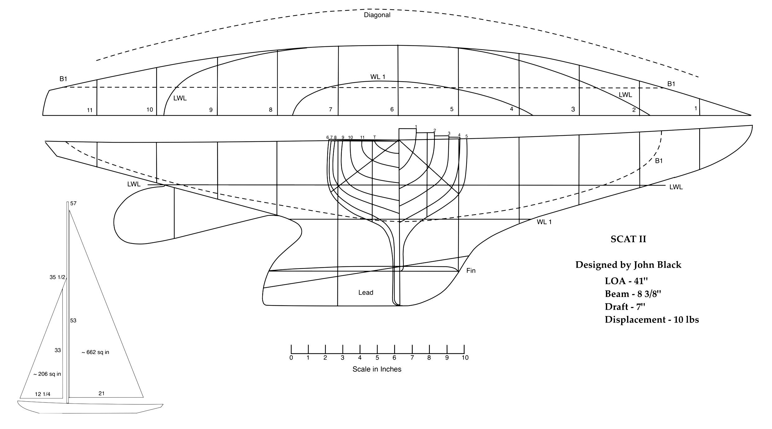
The resulting full drawing for Scat II is shown below. I hope this technique will be used by others to document boats in their possession and permit the building of replicas.