Article and photographs by TMY Staff
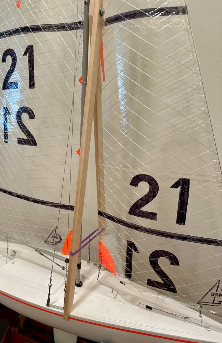
While this is technically not a turnbuckle, it is a good looking and effective way to attach your shrouds to the shroud racks. Finding original fittings is nearly impossible today. Various adaptations have been developed such as using a clevis with a rigging coupler.
They do not look as nice as an all-brass fitting, but they do work. The article “Turnbuckles and Bottle Screws” (published in, The Model Yacht, Vol 5 No 2, Fall 2001) was used as a reference to make this custom “turnbuckle”.
Materials
- One piece of 0.032- by 0.25- by 1.75-in brass strip (K&S Precision Metals, 8240 brass strip)
- One 1-in, 2-56 brass machine screw (hardware store)
- One 2-56 brass nut (hardware store)
- One gold-plated 2-56 Sullivan Clevis (Amazon)
- Hard solder kit (Stay-Brite Silver Solder on Amazon)
- Fine grit foam sanding pad (hardware store)
Tools
- Aviation shears
- Needle nose pliers
- Small hall peen Hammer
- Small bench anvil
- Center bunch
- Drill Bits (#43 and 1/16-in and one larger one)
- Miniature torch
- Drill press or electric hand drill
- File and sanding board
Procedure
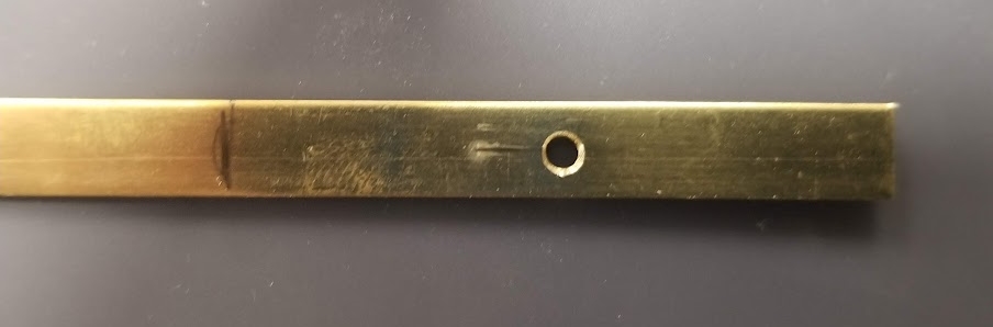
- Measure and mark a piece of the brass strip 1 ¾ in long.
- Mark the center of the brass strip in both directions and center-punch that point.
- Drill a #43 hole at that location and debut the hole with a larger drill bit (i.e., ¼ in)
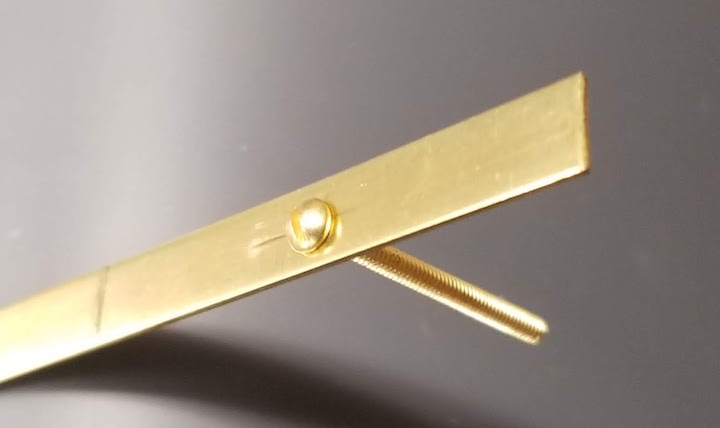
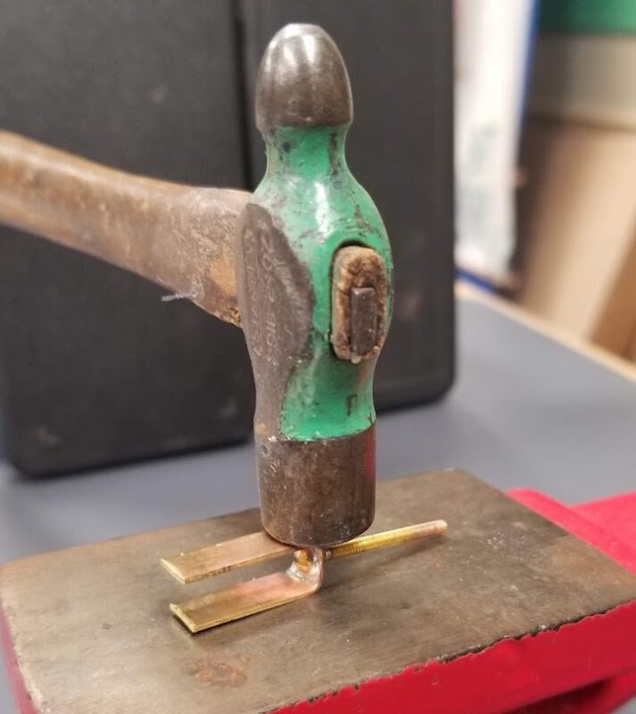
- Using the Stay-Brite hard solder and a miniature torch, solder a 1-in, 2-56 brass machine screw in place in the hole.
- Carefully blow on the soldered pieces until the solder goes dull in appearance (the solder has hardened). This will enable you to take the assembly without the pieces flopping about and place it in cold water to remove the carbon deposits.
- Cut the part from the strip of brass for completion.
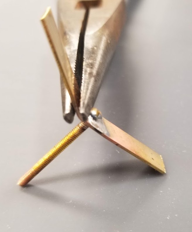
- Bend up the sides of the brass strip with a pair of needle nose pliers. Make sure that you keep the side of the pliers perpendicular with the edge of the brass strip.
- Working from side-to-side keep bending each side of the strip up until they are parallel to each other. Use the needle nose pliers and a small ball peen hammer to complete this step.
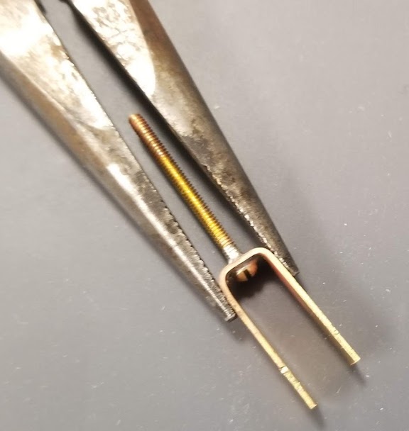
- Measure half way up one leg of the brass strip and mark that location with a pencil.
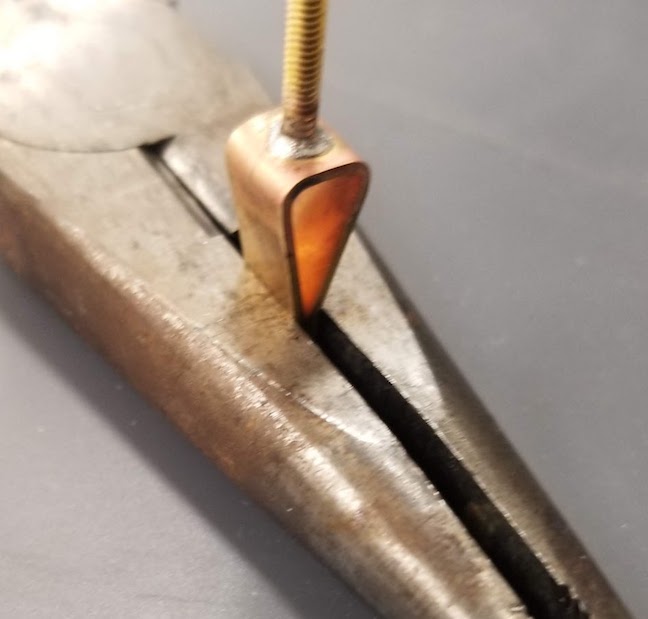
- Take the needle nose pliers and squeeze the strips together at that point marked on the one strip.
- Solder the joint between these legs using the hard solder and the miniature torch. Drip flux into the seam between the legs. Clamp the machine screw with the spring-loaded tweezers allowing the bolt to hang vertically and the legs to be at the bottom. Cut a piece of the solder about 5/16 in long and carefully place it in the “V” created by the legs of the brass strip. Heat the joint where the legs come together until the solder “sweats” into the joint. NOTE: The solder joint holding the machine screw to the brass strip will probably soften, so be careful. Carefully blow on the soldered pieces until the solder goes dull in appearance (the solder has hardened). This will enable you to take the assembly without the pieces flopping about and place it in cold water to remove the carbon deposits.
- If the ends of the strips are uneven, trim them with the aviation shears.
- Measure in ⅛ in from the end of the strips and mark the center point. Center punch this location and drill a 1/16-in hole and debur the edges of the hole.
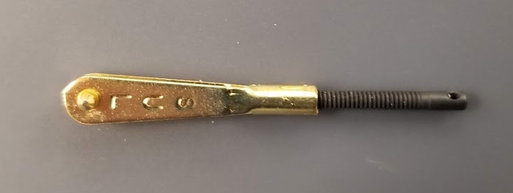
- Shape the end of the brass strips with a slight taper and round the end. Use a file and sanding board to complete this step. (see Fig. 8)
- Using a sanding block, you can “polish” the brass to a very nice finish without having to buff it.
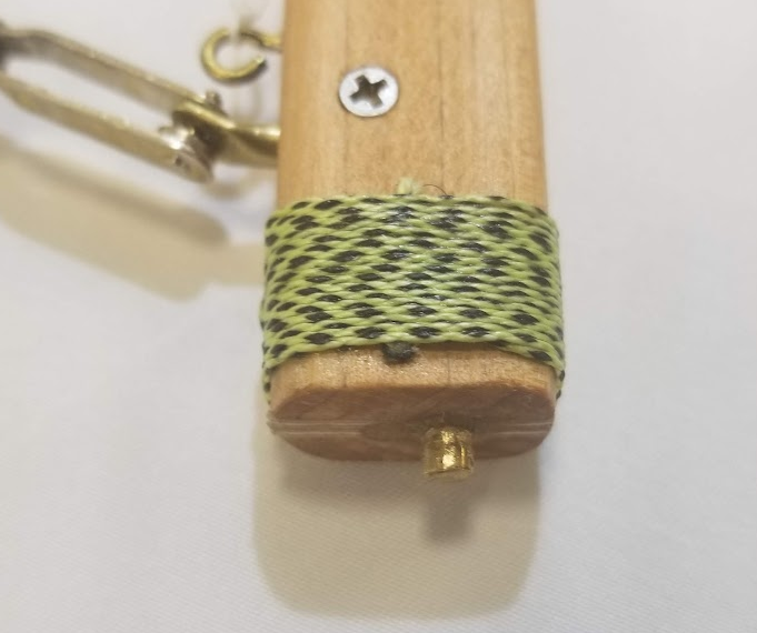
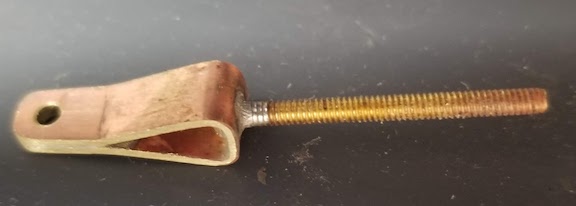
- Assemble the finished turnbuckle as shown.
Procedural Note: Make sure to carefully apply the liquid flux with a small brush to the areas you want the solder to flow. Allow the strip of brass to overhang the edge of your workbench for soldering. Or place the brass strip in a spring-loaded tweezers so the strip is horizontal and the bolt is hanging vertically. Then cut a ⅛-in piece of the solder and place it right beside the head of the machine screw. When you heat the metal, the solder will melt and flow to the areas between the machine screw and the brass strip. The flow of the solder into tight areas is called capillary action (see side bar).
Procedural Note: You may need to hammer the strips at the bend in order them to close completely on each other.
What is capillary action?
| From Wikipedia: Capillary action (sometimes called capillarity, capillary motion, capillary effect, or wicking) is the process of a liquid flowing in a narrow space without the assistance of or even in opposition to, any external forces like gravity. Te effect can be seen in the drawing up of liquids between the hairs of a paint brush, in a thin tube, in porous materials such as paper and plaster, in some non-porous materials such as sand and liquefied carbon fiber, or in a biological cell. It occurs because of intermolecular forces between the liquid and surrounding solid surfaces. It the diameter of the tube is sufficiently small, then the combination of surface tension (which is caused by cohesion without the liquid) and adhesive forces between the liquid and container wall last to propel the liquid. | 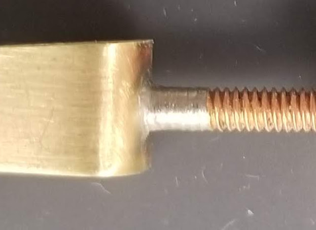 |
In other words, when the soldier liquefies, the soldier itself will be drawn into the joint if you have prepared the mating surfaces well. Just apply a small amount of solder beside the joint that has been fluxed, heat the area to be joined and voilà the solder will wish into the joint.