Model Yachts: How to Design and Build Them
Part III: The Hull (Continued) — Painting — Lead Keel– Finishing Hull — Means of Propulsion — Centre of Lateral Resistance — Area of Sails
I promised to show you how to find the right weight of lead that is required for the keel, but you will have to rig your model, according to instructions which will come hereafter, before you can find it out properly; and I shall, therefore, have to imagine that the rigging part of the busi- ness is finished, and that you know the exact weight of your boat with all her gear, etc., except, of course, the lead keel. I should have liked, had space permitted me, to show you how to do this by figures or theoretically, but as it would take up too much room, it will have to be done practically –that is to say, by experiment.
Firstly, then, take your rigging down and the deck off (which, by the way, is not screwed quite down yet, but only held in place by a screw here and there) and give the hull a coat of ground paint inside and out, and when that is dry give it a sec- ond. Now mark your water line carefully on the model (taking the distances from the sheer plan) with a strong black pencil, and then screw your deck on as before, and put the rigging in place again.
You must then take her to some piece of water, or if you have a bath in the house that will receive her, all the better, and having supplied yourself with some weights, say a 4 lb., a 1 lb., two 1/2 lb., and some smaller weights,-put her afloat, and steadying her by the masts place as many weights along the centre of the deck as will bring her fairly down to the waterline.
Mark around the places lightly where these weights are, and take her out of the water again. You have, of course, taken note of the different amounts in the various places before taking her out of the water, so we will suppose that you had three weights on her, of 4 lb., 1 lb. and 2 lb., making altogether 5 1/2 lbs. Now measure the distance that the centre of the 4 lb. weight was from the stern, and do the same for the other two. Let us imagine these distances to have been, 4 lbs. at 10 inches from the end of the counter, the 1 lb. at a distance of 22 inches from the same place, and the 2 lb. at a distance of 24 inches. Multiply each of these weights by their respective distances, and add the products together, then divide by the total mass of the weights, and the quotient will be the distance that the centre of gravity of your lead keel has to be from the end of counter. Thus in this case, which you may call 13 1/2 inches.
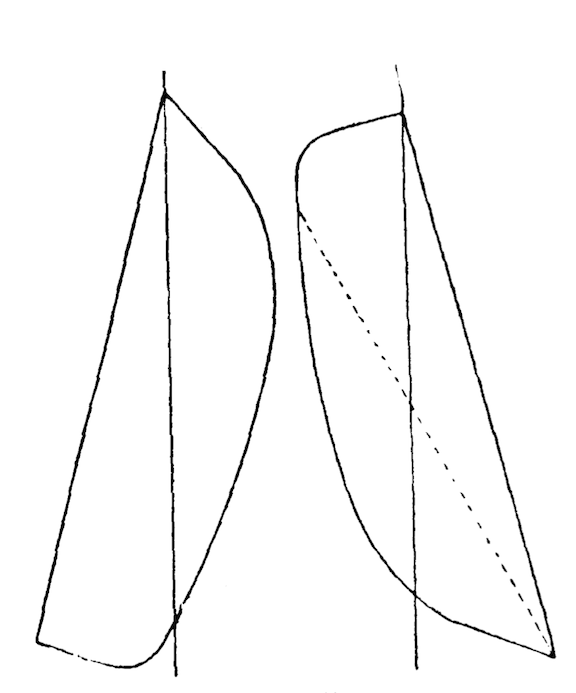
Fig. 10. Determination of centre of gravity.
Mind, this is the distance from the end of counter and not from the end of L. W. L., therefore, I should advise you to mark it at once on your drawing. Before you have your lead cast you should see that the centre of gravity of the pattern comes on the right place (that is, the place you have just found), for if it does not, you must alter the shape of the curve till it comes right, taking care not to increase the weight.
You can now set to work and finish the hull. Get some finely ground pumice powder, or get some pumice-stone and pound it to a fine powder your- self, and with a rubber of cloth and this powder rub the hull down, using a little water at the same time, until all the brush marks are out of the paint. A circular motion will be best for this, but it requires a fair amount of patience since the model must be like a piece of glass when done.
This is only the ground paint that you have smoothed, so you must consider what colour to paint your boat. A black top looks nicest to my idea, and a flesh colour for the bottom shows the black off very well; but you can do about that as you please. Lay two coats of the bottom colour on her, rubbing each coat down as before, and then if you intend painting the top side black run a pencil line along where the two colours are to meet. They should join above the water line all round the boat, but the line should be somewhat higher at the bow than at either the stern or midship section. To get this line on nicely, paste strips of paper along it, on the under side, and then you can paint away without fear of the paint get- ting below the line and spoiling the regularity of it.
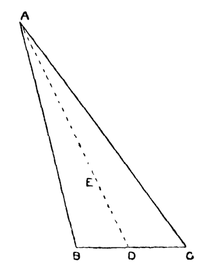
Fig. 11. Triangular sail.
For the black part you should not use ordinary paint, but get some of that stuff which is used for “ebonizing.” It is obtainable at almost any large colourman’s, and a small bottle will go a long way. This is preferable to paint, because it does not require rubbing down, and as the deck should be put on before the top is painted, there is no fear of spoiling the appearance of it.
The deck should be put on with putty for the joint, and screwed down at regular distances. If you do not like the appearance of the screw heads on the deck, they can be covered by a narrow beading of mahogany, fastened all the way round the edge with fine brads, and having here and there slots cut in to allow the water to run off the deck.
A coat of the best copal varnish over the whole will, I think, finish the hull. This varnish, though, should also be rubbed smooth, if it is found to be in the least lumpy when dry; and let me try and impress on you the necessity of rubbing down these coats of paint and varnish in a proper manner, because the rougher the outside of a ship is, or say rather a model, the more resistance she offers in going through the water, and, consequently, the slower she will go. But if this roughness is reduced to a minimum, as by patient scrubbing it can be done, the particles of water have nothing to lay hold of, and, therefore, the resistance is so much less, resulting in a greater speed with the same amount of driving power.
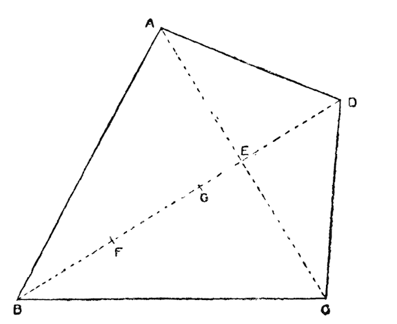
Fig. 12. Four sided sail in which diagonal BD bisects diagonal AC.
Talking of driving power reminds me that I have not yet mentioned anything about the “means of propulsion.”
When a boat is sailing, the forces of the wind acting on her sails can be brought to a resultant acting at a certain point in the plane of the sails termed the “centre of effort,” and the position of this point, in relation to another point, termed the “centre of lateral resistance,” plays a very important function in the sailing qualities of your model.
The “centre of lateral resistance” is a point below the L. W. L., in a plane passing vertically from stem to stern through the centre of the vessel, through which the resultant of all the forces of the water acting on the sides of the vessel when being pushed sideways through the water, acts. In fact, to make this a little clearer, if you could fasten a string to the centre of latera1 resistance, and pull the boat through the water sideways by it, she would come broadside on exactly, and would neither swerve to the right nor the left. You can there- fore easily see that, since the wind striking a vessel tends to drive it sideways through the water (called leeway), the centre of effort and the centre of lateral resistance should be in the same vertical line, for if the former were in front (fur- ther towards the bow) the vessel would, when sailing, tend to turn away from the wind, and thus lose headway; whereas, if the centre of effort were behind the centre of lateral resistance, she would “come up into the wind,” in both cases altering her course, which should be prevented as much as possible in model yachts, because you are not, unfortunately, on board to handle her yourself, and must therefore do all that when she is on shore.

Fig. 13. Four sided sail.
I will now, before I go into the different styles of rig, show you how to find these two rather important centres. Let us begin with the easiest, viz., the centre of lateral resistance. The best way for you to find this is to cut out in thin wood or card- board, the shape of your sheer plan under water, and find the. centre of gravity of that by suspend- ing it first from one corner and then from the other, the place where the strings cross being the centre of gravity, Fig. 10. Now mark this on the corresponding position in your sheer plan, and that will be the centre of lateral resistance. For the centre of effort you must first find the centre of gravity of each sail, as I will show you further on, and square all these centres down on to one horizontal line, and then multiply the area of each sail (which I will show you how to find presently) by the distance that the centre of gravity of that sail is (on the straight line) from the centre of gravity of the head sail. Add these different products together, and then divide by the sum of the areas of the sails, and the quotient will be the distance that the centre of effort of all the sails is from the centre of gravity of the head sail.
Thus, suppose you have three sails, and having found the centres of gravity and squared them down on to a horizontal line (say the L. W. L), work out the areas. We will imagine the area of No. 1 sail (head sail) to be 50 inches, and the area of No. 2, 120 inches, and of No. 3, 100 inches, and the distance of centre of gravity of No. 2 from centre of gravity of No. 1 to be 10 inches, and from No. 3 to No. 1 to be 20 inches.
The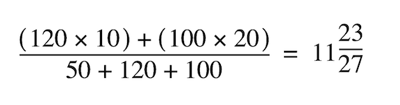 or not quite 12 inches; 12 inches is the distance of the “centre of effort” from the centre of gravity of No. 1 sail. This rule applies to any number of sails, topsails included.
Now we will see how the centres of gravity1 of differently shaped sails are to be found. Let us take an ordinary triangular sail to begin with, as A B C, Fig. 11. Bisect any one side, say B C in D, and join the corner A, opposite the bisected side with the point of bisection D, Then divide D A into three equal parts; and the first point E, i.e., one- third of A D from D will be the centre of gravity of the triangle, or rather in your case of the sail.
For a four-sided sail, Fig. 13, you join D and A C, and from B mark off B F equal E D, and from C mark off G equal A E. Join F G and the centre of gravity of the triangle E F G (found as shown above) will be the centre of gravity of the whole sail. Should it happen that one of the diagonals, say D E, bisects the other A C, then mark off from B the distance B F equal to E D, and one-third of E F from E will be the centre of gravity, G, required, Fig. 12.
The next thing is to find the areas of your various sails, which is as simple as finding the centres of gravity.
Firstly, then, for a triangular sail. From any corner drop a perpendicular on to the opposite side, or, if necessary, the opposite side produced, and multi- ply the half-length of that perpendicular by the side on to which it has been dropped; so if your perpendicular measures 20 inches, and your base 7 inches, the area of the sail will be 20/2 X 7=70 inches. If the sail happens to have one angle a right angle, it will, of course, only be necessary to multiply the half length of one side adjoining the right angle by the whole length of the other side adjoining the right angle.
For four-sided sails simply draw a diagonal, dividing the sail into two triangles, and then find the area of each triangle separately, and the sum of these two areas will be the area of the whole sail.
In drawing out the sail plan you will have to guess first of all the shape and size of the various sails, and then when drawn out you will have to calculate the centre of effort, and see if it comes on the centre of lateral resistance, and if it does not, the sail plan must be altered till it does, by taking some off the fore sails, and adding to the other sails, or vice versa, as the case may be.
The total area of the sails should be about fifty times the area of the midship section below the load water line. If your vessel happens to be pretty deep, you can even increase it up to fifty- five or even more times; but if she is a pretty shallow boat keep it rather less. The area of the mid- ship section you must find approximately by making it into a triangle.
This refers merely to the “fine weather suit” of sails, but you should have three sets of sails for your model, or at all events two, each set being about a fifth less than the preceding one, so that your smallest set, “the storm suit,” will be three- fifths of the “fine weather suit.” I don’t believe in “reefing” model sails, because you can never get the sail to set properly when reefed, and it takes just as long to reef a sail as it does to take it off and bend a fresh one.
You will, of course, see at once why you want three sets (or let us say more than one set, because I know some people that are too lazy to make three sets, and think two almost more than enough). A model wants as much sail as possible in light winds, and, of course, when it comes over squally, some canvas must be taken in, and as tak- ing off either head or top sails would alter the position of the centre of effort, you must have exactly the same rig as for fine weather, only a little smaller, and when it comes to blow a gale she must have a smaller suit still.
I think I can commence now with the next chapter, and show you how, first of all, to choose your rig, and what rigs are most adapted for models, and then how to get your rigging put up; but, of course, you must draw the sail plan out first, and calculate a11 the necessary centres, etc., before you can begin rigging her.