Author and Photographer John Henderson
In Parts 1 and 2 of this series, we discussed how to make preliminary calculations and analyses to predict appropriate sizes, weights, and sail areas suitable for a sailing scale model. We also discussed more detailed calculations covering displacement, helm balance, ballast, and weight distribution. We examined the elements of lines drawings for the original yacht and interpreted them for our modeling application. In all of this, we used a 1:23 scale model of the J-Class yacht Rainbow as a specific example. In Part 3 of this series, we will apply these results to build the model.
There are many successful techniques that make a good sailing model. I will present ones that have worked for me, without claiming that they are the only good methods. I will try to indicate compromises and alternatives where useful. I will assert, however, that the approaches presented in the article will work together to make a successful model, and I suggest that significant changes be considered only after careful thought. I believe that these methods are suitable for any reasonably large R/C sailboat.
Frames and Building Jig
Models are generally built upside down and constructed of wood planking over plywood frames. The frames are typically about ¼ in thick (this may vary depending on your source of plywood, but I think that more than this is overkill). The center of each frame is removed to form a “ring frame”, where the ring is about ¾ in wide. See Fig. 3 in Part 1 of this series. Unless you are desperate to minimize weight, the ring frames can be left in place permanently. Recall from previous articles that the frames must be “undersized” relative to the sections drawings by the thickness of the planking.
Note that frames have “legs” to set the proper vertical height relative to each other (see discussion in Part 1 of this series). These “legs” can be drawn on the sections part of the lines drawing, where the relative height of each frame is shown clearly. The length of each leg is chosen to make the waterline (LWL on the plans) of all the sections be the same height above the building board. Obviously, these legs must be removed after planking and before laying the deck, but do not remove all of the legs until the waterline has been marked on the planking. The legs support the boat and provide a level reference for marking the waterline.
I think it is easiest to taper the edges of the frames before they are installed. The amount of taper of each frame can be determined from the waterlines drawing. Sketch a frame of the correct thickness on this drawing and note the different dimensions of the forward and aft surfaces – this is the amount of taper needed. Note also that the amount of taper changes somewhat as you go around the frame’s perimeter. Also note that the sections drawings give the location of the largest surface of each frame, so frames that are forward of the maximum beam have their aft faces at the section location, and frames aft of maximum beam have their forward faces at the section location.
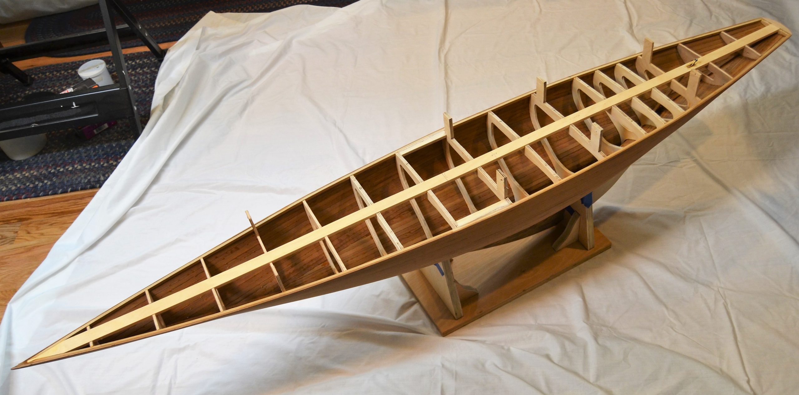
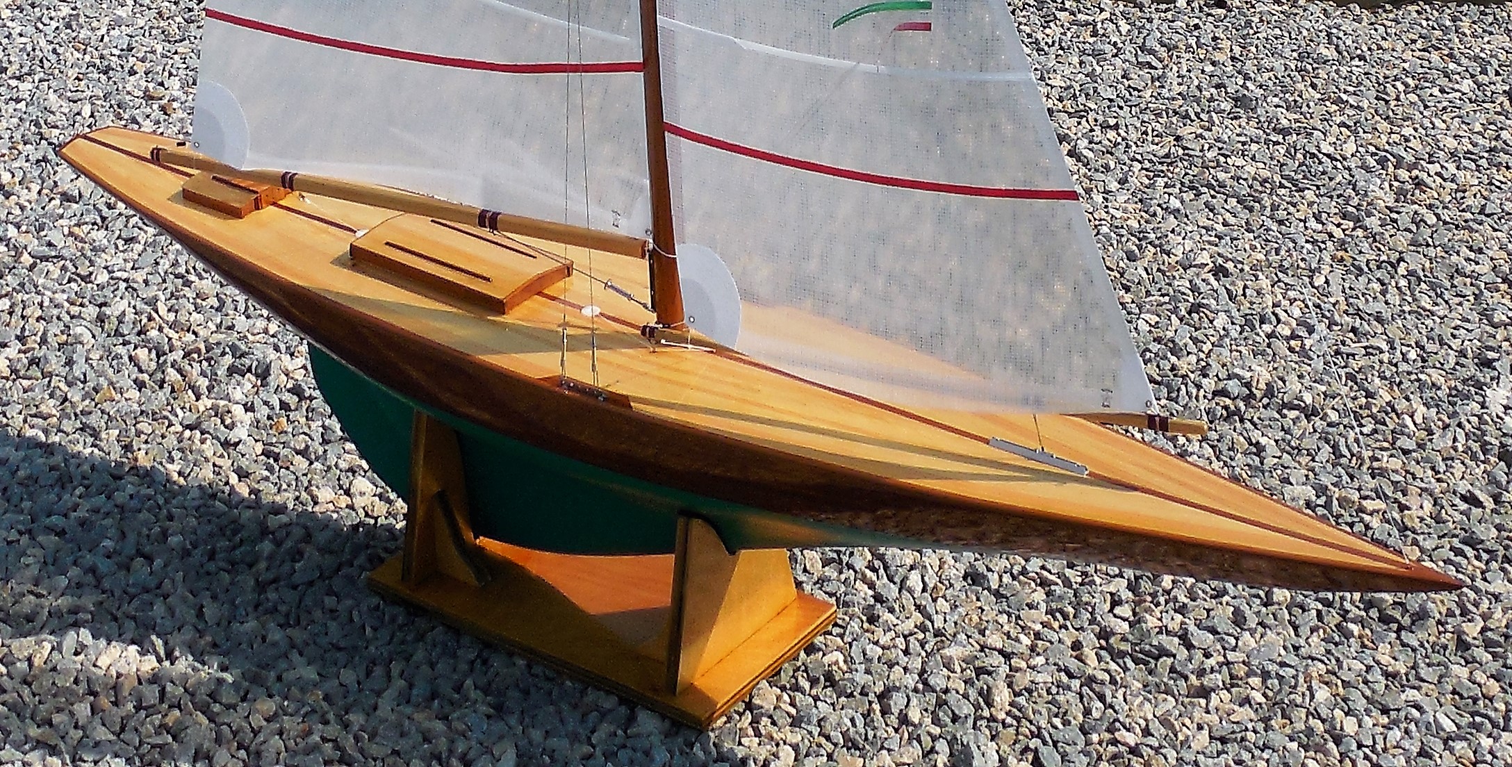
Frames are generally spaced at equal intervals. A spacing of 4–5 in is usually fine for sailing models built as described herein. For convenience, the frames generally correspond to the sections on the drawings. It is sometimes helpful, however, to insert extra frames in areas where the hull shape changes rapidly, such as near the trailing edge of the keel on boats shaped like Rainbow. This can be seen in Fig. 1.
When you lay out your frames for cutting, it is best to mark the centerline and the waterline on each frame. Before you declare success in frame set-up, check very carefully from the bow and stern to be certain that all of the centerlines and all of the waterlines are exactly in line. Also check again that each frame is perpendicular to the building board. Errors and inaccuracies here are very difficult to rectify later.
I think that it is helpful to add sheer clamps and an inner keel to the mounted frames before planking begins. These can be seen in Fig. 1. These longitudinals help to hold the position and angle of the frames during planking.
Since you have already worked out where the mast will be, this is a good time to reinforce the frames near the mast—perhaps with a compression post near the mast’s position, or by leaving a central part of that frame’s ring. It is also good to decide at this point where the chainplates will be fastened and put some hardwood or plywood between the relevant frames to hold the chainplate screws or bolts (best not to rely on the deck planks alone).
Transoms are often tricky, especially if they are curved and raked. Be sure you understand the drawings. I generally add a block of wood to the last (transom) frame and shape that block to form the curved and raked transom. Cheating, maybe, but a lot easier than trying to plank such a transom.
Ballast
You need to work out the weight and location of the lead ballast. If you are working from plans for a full-size boat, the indicated ballast volume may or may not apply to your model. In general, since models will not be carrying freight or have interior furniture, the ballast/displacement ratio is higher than full-size boats. Said differently, you may need more than a scale-sized volume of lead in order to get the boat to sink down to its lines.
So, how much lead ballast do we need? In Part 2 of this series, we calculated the total volume (and hence weight) of the boat. This weight is the sum of the weights of the bare hull, the deck, the rig and sail, the radio gear, the rudder, and the ballast. You can weigh your radio gear exactly, but the other components will have to be estimated at this point. If you make a lead casting, the goal should be to get reasonably close but not go over the required weight. This allows for correction and fore-aft trim adjustment when you are nearing completion.
These weight estimates are, or course, heavily dependent on the size of the model, but here are some actual component weights for the Rainbow example model of this series (the model was about 68 in LOA, 11-in beam, and weighed about 26 lb when finished):
- bare hull, without epoxy coating or deck = 3.3 lb
- hull with epoxy coating (not fiberglass) and rudder = 4.2 lb
- radio gear (2 sail servos, small rudder servo, batteries, receiver) ~ 1 lb
- mast, sails, rigging ~ 2 lb
- ballast ~ 16 lb
The weight should be arranged so that the center of gravity is at the same fore-aft location as the center of buoyancy, calculated in Part 2 of this series. You can check this on dry land by suspending the boat at the calculated center of buoyancy and making sure that it hangs level. The dominant single weight item is the lead ballast, which should be located at the center of buoyancy. Desirably, the radio gear should also be located at the center of buoyancy, but heavy items, such as the battery, can be moved to “trim” the weight distribution. To protect yourself against inaccurate estimates or other surprises, it is prudent to save a little ballast for last minute addition—perhaps less than a pound for a model of this size. The biggest unknown is probably the hull weight, which can be determined before the exact ballast casting needs to be made and installed.
If you plan to make a lead casting for the ballast, you must work out its shape (unless it is a bulb on the bottom of a fin). It may need to match the keel shape and its volume distribution must match the required center of gravity. The full-size boat plans are a guide for the distribution, but they may not be exact for modeling purposes. Estimate or calculate (use Simpson’s Rule, per Part 2) the volume of lead, and note that solid lead weighs 0.41 lb/in3. You will make a wooden “plug” that is the exact shape of the lead and use it to form the mold for casting.
If you have trouble calculating the volume, you can work with an approximation: Before you cut and shape the wooden “plug”, measure and calculate the volume (length x width x height) of the (desirably) rectilinear wood block from which you will make the keel shape. Weigh that rectilinear block and then calculate its density in ounces per cubic inch. Then make a wooden shape for the lead casting from this block of wood. Weigh this keel-shaped wood. Dividing the weight of your shape by the density of the original block gives the volume of your shape in cubic inches, which you can multiply by 0.41 to get the weight of lead of that shape.
For a simple sand casting, make sure the shape is appropriate for getting the plug out of the sand. Add support for fastening the ballast with bolts. An alternative is lead shot, which can be dumped into a hollow hull (make sure it is strong enough) and epoxy added to stabilize everything. Note that lead shot is 2/3 of the density of solid lead (I think this is independent of shot size as long as the shot balls are small compared with the space they fill), so the center of gravity will be higher, with some decrease in righting moment. It is probably a good idea to fiberglass the outside of the hull where it will contain the lead shot, just for strength.
Planking
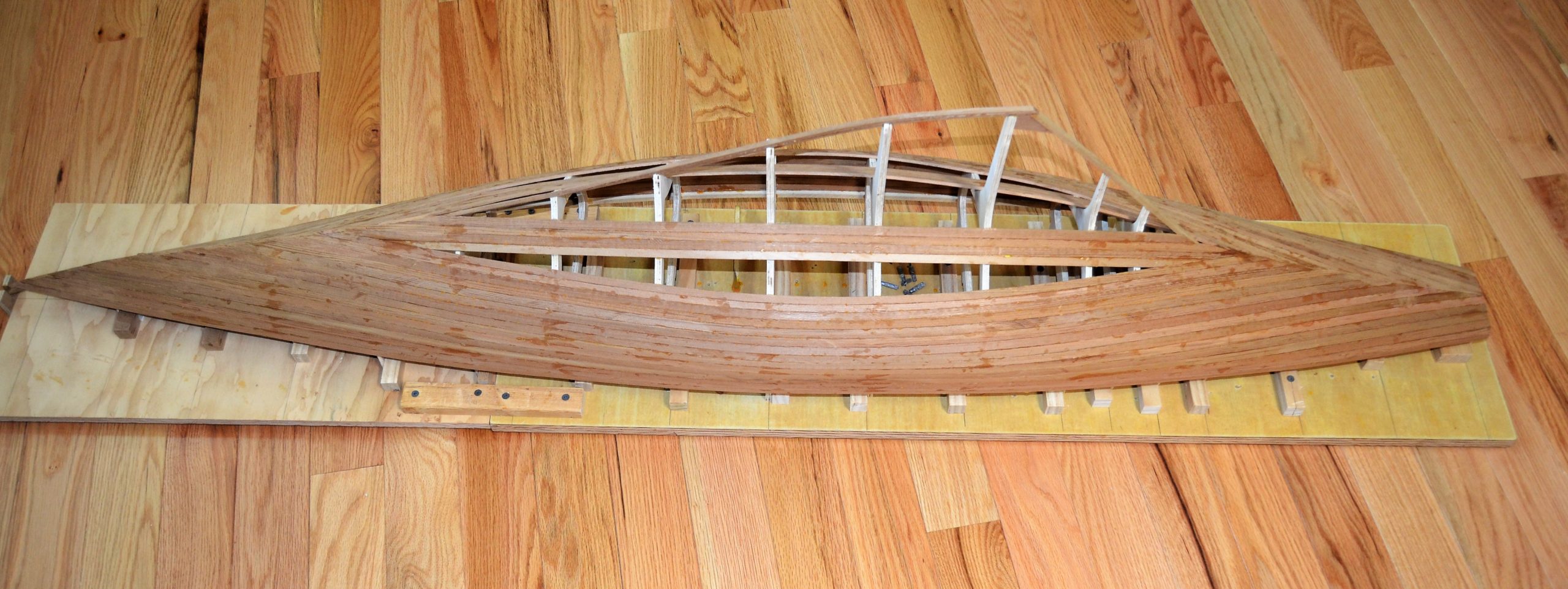
I prefer cedar (usually western red cedar) for planking, and I generally cut it into ⅛ by ⅜-in strips. Straight-grained lumber is available, and it can be cut, planed, sanded, and bent easily. For a model like this (i.e. one that is relatively long and narrow) these strips take the required bends without soaking or steaming. That said, my own practices do not always follow the traditional and “correct” wooden boatbuilding technique of spiling each plank so that every plank runs the full length of the boat. Instead, I use the generally accepted strip planking practice of running full-width planks parallel to each other until the edge-set (sidewise bend) becomes troublesome, and then I start a new section of planking where the planks can lie easily on the curve of the hull. The two sections will meet in a kind of football-shaped gap, which is gradually filled in. See Fig. 2.
You will probably find that the overhanging stern area requires considerable twist in the planks. I try to maintain full-length planks, for appearance sake, because I varnish the hulls. Painted hulls do not need to be so fastidious. I get a little more casual about “stealer” planks once I get below the waterline, where it will be painted. Planking the aft end ofthe keel, near the rudder, is often the most problematic, but it yields to patience and care.
For boats like this one (long and narrow), the planking above the waterline will not be much different regardless of whether you spile or strip-plank.
The “football”, which might be undesirable if visible, is entirely below the waterline, where it is covered with bottom paint. I note further that the original Rainbow was built of steel, so faithful reproduction of the building material and technique is not practical in a sailing model.
Successful strip planking, especially if you intend a hull finished bright, does require some careful beveling of the plank edges, and some careful tapering of the planks where they meet in the “football”. Take the trouble to make the edges fit and the planks to lie as uniformly as possible. I generally do not cover the hull with fiberglass cloth, except in areas of stress such as the ballast keel. Instead I simply coat the planks with a couple of applications of epoxy resin. With good fairing before applying the epoxy and with careful sanding of the epoxy itself, the wood is sealed, and a smooth surface is created for the application of varnish and paint. If you plank carefully, you don’t need a complete covering of fiberglass cloth for strength or for water tightness.
Strip planking, with minimal spiling, almost always works better on long, narrow hulls, such as pre-WW2 racing boats.
Most Marblehead Class hull shapes can probably be built without too much spiling. Shorter or fatter boats (a catboat would be an extreme example) probably would require spiling and maybe steaming.
The interior of the boat should be waterproofed. An easy way is to apply one or two coats of epoxy resin (without fiberglass cloth) to the interior of the hull before the deck goes on. Waterproofing the underside of the deck is not so straightforward. A plywood deck can simply be epoxy-coated on the underside before it is attached. Epoxy could also be applied to each plank of a planked deck before application, but this is likely to be very wasteful of expensive epoxy. I have had good luck with simply coating the underside of each plank with water-resistant wood glue (e.g., the water- resistant versions of Titebond), which is less expensive, less wasteful because you don’t have to pre-mix a fixed quantity, and dries to a sufficiently “waterproof” coating for the underside of the deck.
The deck itself could be sheet plywood or strip planks. Plywood may be less desirable, because decks generally involve compound curves (i.e., the deck curves both fore-and-aft and athwartships), which are difficult to do well in sheet material. Strips could either run parallel to the centerline or parallel to the edge of the deck. For long and narrow boats, following the curve of the deck edge is not difficult and generally does not require steaming. For models in the length range of 5 ft, deck planks of ⅛ by ¼ in are reasonable.
Rudder Post and Tube
The rudder post fits into a properly sized tube (I generally use a 3/32-in post and a ⅛-in OD tube). The tube is mounted with epoxy at the bottom of the boat and extends upwards either through the deck or as high as possible below deck level. Sometimes, if the top of the tube is below deck level a small amount of water works up the tube. I think this quantity is more annoying than dangerous, but if it bothers you then extend the tube above deck level – of course, this requires that the rudder-servo connection be above the deck also.
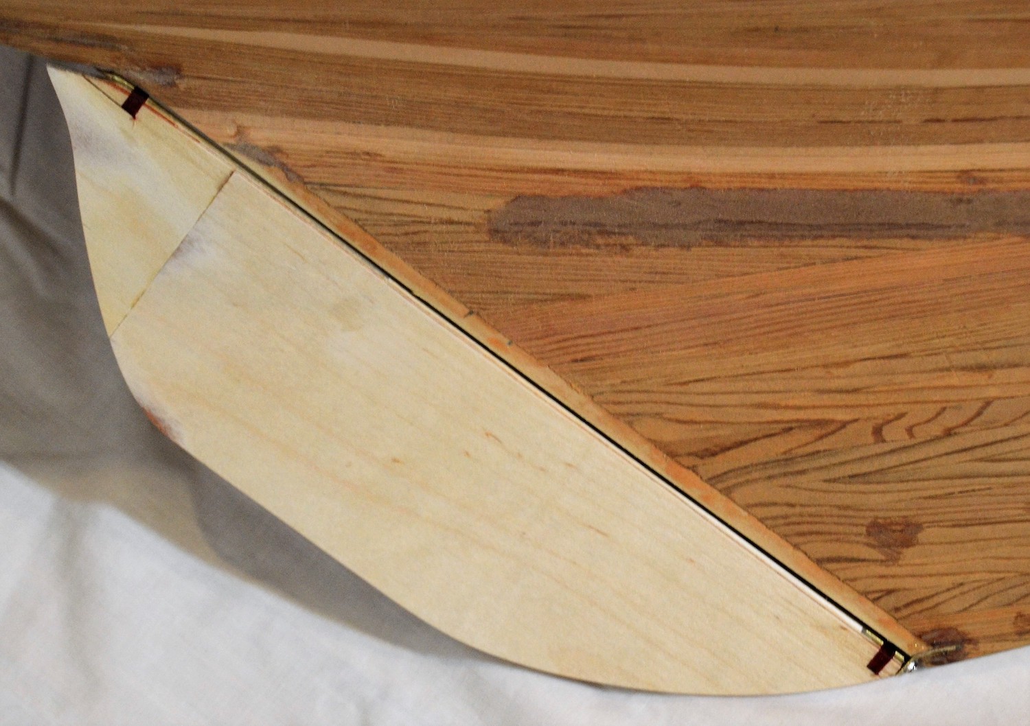
If the rudder is on the trailing edge of the keel or is mounted to a skeg, then it is good practice to install a hinge at the bottom. There are many good solutions. My own favorite is to attach a small flat plate to the bottom of the keel, solder a 2-56 nut to this plate, mount a ⅛-in OD tube at the bottom of the leading edge of the rudder, and run a 2-56 screw through the nut and into the short tube on the rudder. See Fig. 4. Note the reinforcing wrappings around the rudder post at the top of the rudder and the short tube at the bottom of the rudder.
Hatches
Hatches are a necessary evil. Seaworthiness is never improved by the addition of hatches. They should be as small and narrow as is consistent with maintaining and replacing the radio gear. Their location should be planned before you start construction. Desirably, they are over the center of gravity, since radio gear is non-negligible weight. They must be far enough away from the mast that they do not interfere with a boom vang or the sheets. It should not be too difficult to remove the hatch cover, especially if the ON/OFF switch is inside. And, above all, a hatch must be watertight.
I think that it is often convenient to use the hatch opening as a carrying handle, since it is at the center of gravity. This adds the additional design parameter of strength. Make hatch frames that are robust enough, and glue them securely to the hull frames.
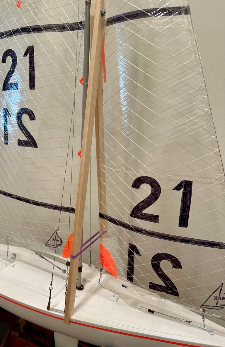
Water tightness can be achieved in several ways. Arguably, the best is to screw down the hatch cover onto some kind of rubber gasket. This is also the least convenient at the launching site, especially if the switch is inside. An alternative that may work well enough (and is what I normally use) is to raise the hatch frame ~½ in above the deck, keeping the hatch (especially the hatch width) as small as possible, and making a carefully fitted hatch cover. This is what is shown in Fig. 3. If you have any doubts, put your boat into the water, grab the top of the mast, and pull it downward, observing how far you can heel the boat before the hatch edge is submerged. You may or may not be pleased with the results, and you may become convinced that a screwed-on, gasketed hatch is in your best interest.
Radio Installation
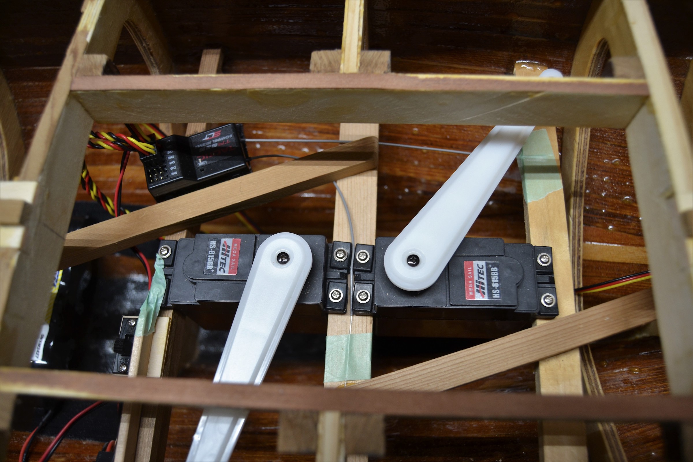
This topic has been covered thoroughly in many articles for many classes of R/C boats. There is nothing unusually challenging about installations in one-off scale models. Work out how the sail and rudder servos will be arranged before the deck goes on. Install any needed supports for the servos. It would be prudent to do a temporary installation of the servos to be sure everything works, BUT, leave them in place only if you are certain that you can get access to every screw and adjustment after the deck is on. Otherwise, remove them and re-install them after the deck is in place. Plan servo and battery locations with both hatch access and weight distribution in mind. Fig. 5 shows the mounting of the sail control servos, with all mounting screws and servo arms accessible through the hatch.
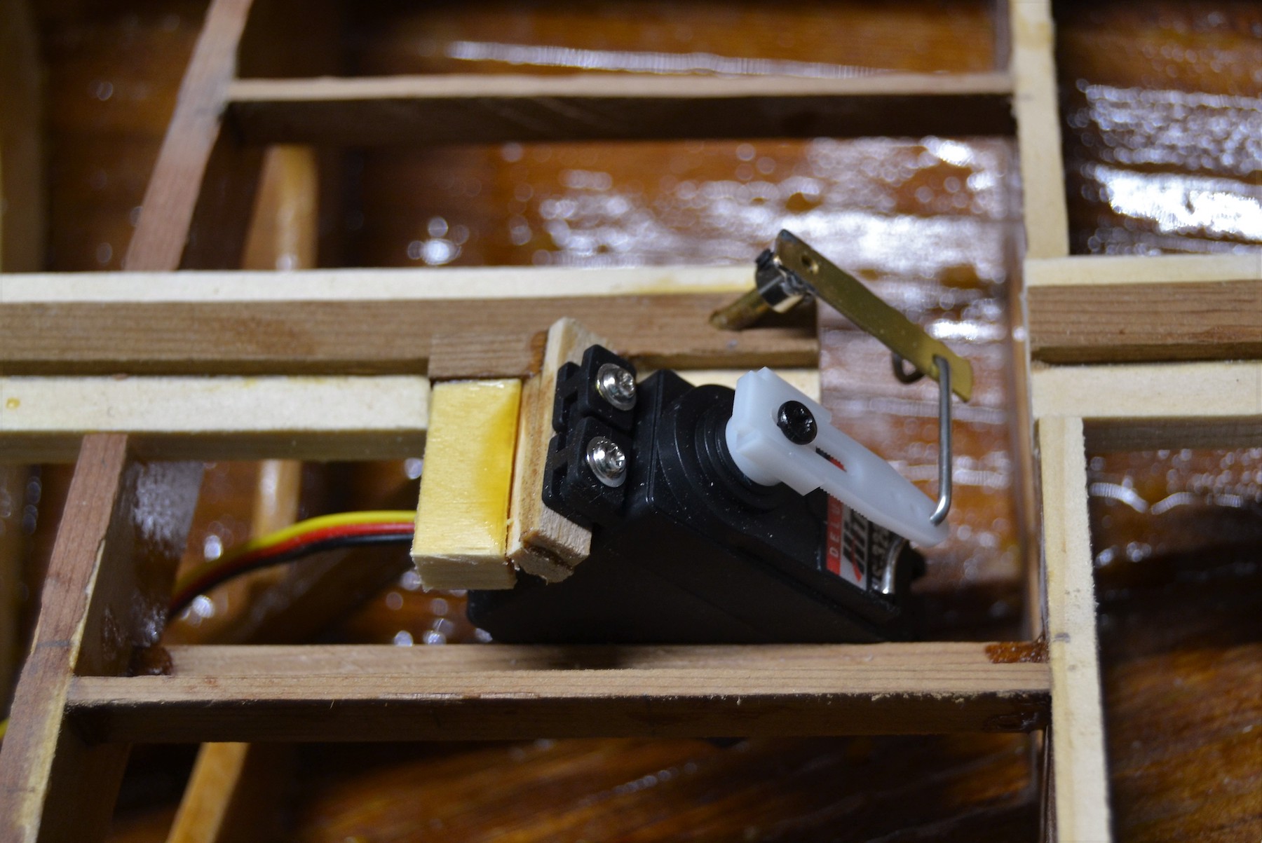
Fig. 6 shows the installation of the rudder servo adjacent to the rudder post. (The rudder post is the angled brass tube emerging from the kingplank, and the servo is offset to port.) The rudder servo’s arm and the “tiller” arm on the rudder post should move in a parallelogram. The photo shows that the servo is mounted at an angle so that the axis of rotation of the servo arm matches the axis of rotation of the rudder post.
As stated at the outset, this article describes techniques that have worked for the author. Other approaches are possible. I encourage written contributions that describe other successful methods (or lessons learned from unsuccessful methods).