

These revised Vintage Marblehead (VM, 50/800) Rating Rules of 2025 shall govern Vintage Marblehead activities from date of publication until revised by consensus or recommendation by Vintage Marblehead class owners.
It is reasonable to expect that the class rules or plans may evolve with time to improve clarity, correct unforeseen problems, or embrace advancing R/C technology. It is the intent of the class that any potential changes not disqualify existing boats.
All Vintage Marblehead model yachts participating in racing competition sponsored by US VMYG must comply with these class-rating rules. It is the responsibility of each skipper to prepare his boat in accordance with the Rules and Specifications referenced or included in this document. The intent of the US VMYG is to encourage participation and to simplify any certification or measurement processes as much as is consistent with fair racing.
The rating rules for the Vintage M divisions are based on the Marblehead 50/800 Class rule adopted by the Model Yacht Racing Association of America (predecessor of the American Model Yachting Association) April 14, 1932 and corrected June 1, 1939. Subsequent editions were “corrected” to accommodate the evolving Marblehead 50/800 development class.
For racing purposes, Vintage Marblehead fleets may be separated into “Traditional”, “High Flyer”, and two “Classic M” (C1 and C2) divisions. The separation is based on design characteristics. In general:
Early vintage design types (”Traditional”) are identified by practices such as skeg- or keel-mounted rudders and relatively shallow draft; this is typical of design practices in the period roughly from 1930 to 1945.
Later vintage designs (“High Flyer”) may have spade or balanced rudders (i.e., rudders not attached to a skeg or keel) and somewhat deeper draft; this is typical of design practices roughly from 1945 to 1970.
Designs in the period roughly from 1971 through 1990 (“Classic M”) adopted more modern materials and somewhat deeper keels with lower displacements and loosened restrictions on keel shape (e.g., prognathous keels were permitted).
Note that the determining factor is the design type, not the actual date of the design. This is meant to encourage new designs that fall within the spirit of any Vintage Marblehead subclass design types and also to encourage reproductions of earlier designs.
For the purposes of these Class Rules, the following Definitions apply:
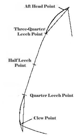
- Aft Head Point (MAINSAIL and HEADSAIL): The intersection of the leech extended as necessary to bridge a cut-out or a rounded corner and the line through the head point at 90° to the luff.
- Bilge-boards: Also known as bilge keels. Underwater appendages, usually found in pairs, that are attached to or protrude from slots in the hull in the region of the turn of the bilge.
- Centerboard: An appendage to the boat’s underbody that can be extended below the surface of the water that is neither a “keel” nor a “rudder/skeg” as those terms are defined herein. In common usage, a “centerboard” is an unweighted or lightly weighted movable underwater appendage.
- Clew Point: The intersection of the foot and the leech, each extended as necessary to bridge a cut-out or a rounded corner.
- Double Luff: A sail with more than one luff, or a sail passing around a spar and attached back on itself.
- Foot: The bottom edge of a sail.
- Head Point:
- MAINSAIL: The intersection of the luff, extended as necessary, and the line through the highest point of the sail at 90° to the luff.
- HEADSAIL: The intersection of the luff, extended as necessary, and the line at 90° to the luff passing through the highest point of the sail excluding attachments and any luff tape/tabling.
- Hoist: The maximum height of rig, measured from the deck to the lower edge of the headboard or eye.
- Hull: For composite or fiberglass hull weight this is to be the bare hull with sheer clamps only. No other internal structure is included in this weight.
- Keel: A fixed appendage along the centerline of the boat’s underbody. Its requirements and constraints are specified in the “Hull” and “Prohibited” sections of the Class Rules.
- Leeboards: Similar to bilgeboards, except that they typically attach to the topsides and extend down into the water immediately adjacent to the boat.
- Leech: The aft edge of a sail.
- Leech Points:
- QUARTER: The point on the leech equidistant from the half leech point and the clew point.
- HALF: The point on the leech equidistant from the head point and the clew point.
- THREE-QUARTER: The point on the leech equidistant from the head point and the half leech point.
- Luff: The fore edge of a sail.
- Measured Weight: The assembled hull ready to sail with radio, batteries, and rudder. This does not include rig and keel/bulb. For boats with permanently affixed keels, the assembled hull is placed on its side with a scale under the hull, with the bulb sitting at a similar height on a fixed surface, the weight shown on the scale will have 4 oz (or ¼ lb) removed to account for the half weight of the fin.
- Rudder: An underwater appendage used for steering. Its requirements and constraints are specified in the Rules.
- Sails: An item of equipment used to propel the boat. It includes any of the following added parts: sail reinforcements, batten pockets and associated fittings, windows, stiffening, tabling, sail edge ropes and wires, attachments, and other parts as permitted by class rules.
- Skeg: A fixed appendage to which a rudder may be attached. Its required attributes are described in the “Hull” section of the Rules.
- Tack Point: The intersection of the foot and the luff, each extended as necessary to bridge a cut-out or a rounded corner.
The detailed specifications used to distinguish the different divisions are given below.
Traditional Vintage Marblehead (period roughly from 1930 to 1945)
Design Formula
A Vintage Marblehead model is a sloop-rigged monohull model sailing yacht with an overall length of 50 ± 0.25 in. Total sail area shall not exceed 800 in2.
Prohibited
- Sliding or adjustable keels
- Centerboards
- Leeboards
- Bilge-boards
- Bowsprits
- Transom-mounted rudders or rudders that extend aft of the transom
- Outriggers, pontoons, or twin hulls
- Movable or shifting ballast
- Prognathous keels: No portion of the keel appendage, including the lead, may project forward of any portion of the leading edge of the keel fin above
- Metal fin keels
- Materials with a density greater than lead
- Carbon fiber or Kevlar in the hull, keel, rudder, or rig
- Fabric, film, balsa, foam or fiberglass decks
- Mylar or other modern plastic-like materials in sails
- Swing rigs
Hull
- Wooden hulls may be built using plank on frame or horizontal and vertical lifts. It is permissible to cover a wood hull and deck with a light layer of fiberglass cloth to prevent leakage. Balsa wood is not permitted in the hull fairbody (i.e., the “canoe-body”). Balsa may be used as a filler material in the core of a rudder or keel, but balsa cannot be considered the primary strength in these appendages.
- Fiberglass hulls laid up in a mold are permitted. Minimum weight of fiberglass hulls is 2 lb.
- Garboards: Garboards shall be hollow, with not less than a 1-in radius in the area of the keel fin. This may be checked by use of a disk 2 in in diameter fitted to the garboard at amidships section.
- Modern adhesives are permitted to produce a strong hull impervious to leaks.
- Draft, measured from the waterline to the bottom of the keel or keel bulb, shall not exceed 12 in on a model yacht fully rigged and ready to sail.
- All ballast must be fixed and shall not be changed during a race or series of races.
- Model total weight shall be in keeping with that of the period.
- Bumpers are mandatory and are limited to 0.5-in overhang. Bumpers are not included in the overall hull measurement.
- Rudders shall be keel- or skeg-mounted in keeping with the design characteristics of the period. It is permitted to enlarge the area of the rudder from its original size to achieve acceptable steering with radio control. The area of a skeg must be at least 50% of the area of the rudder; for this calculation, “rudder” is the portion of the rudder/skeg combination that articulates and does not include the area of the fixed skeg. Balanced or spade rudders are not allowed. Changing rudders during a race or series of races, except in bona fide cases of damage, is prohibited. There can be no more than one rudder.
- The minimum keel fin chord length is 5 in. No more than one keel fin is permitted. The keel must be attached to the hull underbody on the centerline. Neither the keel nor any part of it shall be movable (e.g., keel “trim tabs” are not permitted). Rudders may be attached to the trailing edge of the keel, in which case they are the single permitted rudder.
- Removable keels are allowed, but changing keels (or the position of the keel) during a race or series of races, except in bona fide cases of damage, is prohibited.
Deck
Decks shall be constructed of wood: solid, planked, or plywood.
Rig
- Bermuda, Marconi, jib-headed mainsail, gaff, gunter, wishbone, and other types may be used.
- Alternate rigs are permitted provided the sail area does not exceed 800 in2. Any such alternate rigs must have examples in design practices of the period.
- Masts and spars shall be constructed of the materials of the period, primarily wood. Round aluminum tubing is permitted. “Round aluminum tubing” means: 1) a constant round cross section over the full length of the mast; 2) the tubing must not be slotted; 3) no external structure that creates a slotted sail track may be affixed to the mast. The diameter of the round aluminum tubing shall be ≥0.75 in. Note that traditional jacklines and lashings or loops of line may be used to hold and support the sail.
- Maximum diameter of round wooden spars is 0.75 in. If spars are airfoil-shaped, rectangularly shaped, or otherwise not round, then the maximum permitted cross-sectional dimension of a spar is 0.75 in.
- Maximum height of the head of the mainsail above the deck (see sail measurement) is 85 in.
- Height of the jib head stay above the deck shall not exceed 80% of the height of the head of the mainsail above the deck.
- Hollow masts and spars, permanently bent masts and spars, and rotating and bipod masts are allowed.
Fittings
Fittings for deck and rig should be made of brass, stainless steel, or other non-corrosive metal in keeping with materials and practices of the period.
Sails
- Sails may be constructed as either a single or multi-panel sail.
- The body of each sail shall be made of woven cloth, such as cotton, a cotton-synthetic blend, Dacron®, or nylon, such as light spinnaker cloth. No material other than woven sailcloth is allowed for tablings or corner reinforcements in the head, tack, or clew of any sail except sail reinforcing tape.
- Mylar or other modern plastic-like materials are not allowed.
- Roach of sails shall not exceed 2 in. Rounded foot of loose-footed sails shall not exceed 1 in.
- The roach and the rounded foot of sails shall be a continuous, arc-like curve from head to clew and from clew to tack.
- Mainsail battens shall not exceed four in number and 4 inches in length, and they shall divide the mainsail leech into approximately equal parts. Headsail battens shall not exceed three in number and 2 inches in length, and they shall divide the headsail leech into approximately equal parts.
- Headsticks or headboards shall not exceed 0.75 in across the base for headsails and mainsails. No other wire or stiffener shall be put in the head of the sails.
Sail measurement

- Rig and mainsail measurements are taken from the underside of the 0.75-in base of the mainsail headboard. Thus, the height of the mainsail above the deck measurement and the area of the mainsail are taken from this point.
- Calculation of sail area: The measurement of sails is specified in the 1958 MYRAA Handbook. Only the “triangular” sail area, excluding roaches and the rounded foot of loose-footed sails is measured. The above drawing indicates the layout for triangular sails. The luff is measured from the lowest point on the tack of the sail to the bottom edge of the stick or headboard. If the sail has no headboard, the measurement is taken from a point at the head of the sail where its width is 0.75 in. The diagonal is measured from the aft edge of the clew to the closest point on the luff. The sail area of each sail is given by:

- The sum of the areas for the jib and mainsail must be less than 800 in2.

All Vintage Marblehead Model Yachts shall be officially registered with the VM Class Coordinator to obtain an official sail number. Sail numbers shall be preferably black, 3 in tall, 0.5 in thick, and they shall be affixed to both sides of the mainsail between the second and third battens on a line perpendicular to the leech. The VM insignia consists of a red “V” nested in the top of a black “M” as shown. The letters are 1.5 in tall, 1.25 in wide, and 0.25 in thick. The “V” is separated from the “M” by 1/16 in. The insignia should be placed in the upper quadrant of the mainsail and only on the starboard side.
Radio Control
Only the rudder, headsail sheet, and mainsail sheet may be adjusted by radio control.
High Flyer Vintage Marblehead (period roughly from 1945 to 1970)
Design Formula
A Vintage Marblehead sloop-rigged monohull model sailing yacht has an overall maximum length of 50 ± 0.25 in and a total sail area not to exceed 800 in2.
The rules for the High Flyer division are the same as those for the Traditional division except for the following:
- Rudders may be of the spade or balanced type; that is, independently suspended and not attached to the keel or a skeg. Marbleheads of any design of the Traditional period that use a spade rudder shall be classified with the High Flyer division.
- Draft of a High Flyer model yacht fully rigged and ready to sail shall not exceed 16 in. There is no minimum keel fin chord length required, but fin profiles should conform to the practices of the era, e.g. “seal flipper” or tapered.
Classic M Vintage Marblehead (period roughly from 1971 to 1990)
The Classic M division is intended to provide a place for Modern Marblehead models designed and built during this time period to sail competitively. This was a very active development period for Marbleheads with many new and updated designs, improvements and changes in materials, and the transition toward production-built rather than home-built models.
This class is further divided into the time periods Classic 1 (C1) to be defined as 1971–1979 and Classic 2 (C2) to be defined as from 1980–1990. C1 designs typically have displacements greater than 13 lb with shallower keels up to 16 inches. C2 designs typically are lighter boats with composite hulls and rigs with deeper keels to about 20 inches. T keels, i.e. prognathous keels were allowed with the forming of the AMYA in 1970 and a change in the MYRAA rules around 1972 and are allowed in both subclasses
Classic 1 (C1) Marblehead (period roughly from 1971 to 1979)
Design Formula
A Marblehead model is a sloop-rigged monohull model sailing yacht with an overall length of 50 ± 0.25 inches. Total sail area shall not exceed 800 in2. Draft of a Classic 1 model yacht fully rigged and ready sail shall not exceed 16 inches.
The rules for the Classic 1 division are the same as those for the High Flyer division except for the following:
Hull
- Wooden hulls may be built using plank on frame or horizontal and vertical lifts. It is permissible to cover a wood hull and deck with a light layer of fiberglass cloth to prevent leakage. Balsa wood is not permitted in the hull fair body (i.e., the “canoe-body”). Balsa may be used as a filler material in the core of a rudder or keel, but balsa cannot be considered the primary strength in these appendages.
- Fiberglass hulls laid up in a mold are permitted. Minimum weight of fiberglass hulls is 2 lb. Minimum measured weight (hull, radio, and rudder) is 3.5 lb.
- Garboards: Garboard radius is unrestricted.
- Draft, measured from the waterline to the bottom of the keel or keel bulb, shall not exceed 16 inches on a model yacht fully rigged and ready to sail.
- All ballast must be fixed and shall not be changed during a race or series of races.
- Model total weight ready to sail shall be in keeping with that of the period, which is 13 lb minimum.
- Bumpers are mandatory and are limited to 0.5-inch overhang. Bumpers are not included in the overall hull measurement.
- Rudder shape is unrestricted. Rudders may be of the spade or balanced type; that is, independently suspended and not attached to the keel or a skeg. Changing rudders during a race or series of races, except in bona fide cases of damage, is prohibited. There can be no more than one rudder.
- No more than one keel fin is permitted. The keel must be attached to the hull underbody on the centerline. Neither the keel nor any part of it shall be movable (e.g., keel “trim tabs” are not permitted).
- Removable keels are allowed, but changing keels (or the position of the keel) during a race or series of races, except in bona fide cases of damage, is prohibited.
Deck
- Decks shall be constructed of wood and/or fiberglass.
Rig
- Bermuda, Marconi, jib-headed mainsail, gaff, gunter, wishbone, and other types may be used.
- Alternate rigs are permitted provided the sail area does not exceed 800 in2.
- Masts and spars shall be constructed of wood, aluminum, or steel. Note that traditional jacklines and lashings or loops of line may be used to hold and support the sail.
- Maximum diameter of round spars is 0.75 inches. If spars are airfoil-shaped, rectangularly shaped, or otherwise not round, then the maximum permitted cross-sectional dimension of a spar is 0.75 inches.
- Maximum height of the head of the mainsail above the deck or “hoist” (see “Sail measurement”) is 85 inches.
- Height of the jib head stay above the deck shall not exceed 80% of the height of the head of the mainsail above the deck.
- Hollow masts and spars are allowed. Permanently bent masts and spars, rotating, and bipod masts are prohibited.
Sails
- Sails may be constructed as either a single or multi-panel sail.
- The body of each sail shall be made of woven cloth, such as cotton, a cotton-synthetic blend, Dacron®, or nylon, such as light spinnaker cloth. No material other than woven sailcloth is allowed for tablings or corner reinforcements in the head, tack, or clew of any sail except sail reinforcing tape.
- Mylar® or other modern plastic-like materials are not allowed.
- Roach of sails shall not exceed 2 inches. The rounded foot of loose-footed sails shall not exceed 1 inch.
- The roach shape may be a continuous curve from head to clew or parallel with a 35.5-inch radius at the ends. See “Sail measurement”.
Classic 2 (C2) Vintage Marblehead (period roughly from 1980 to 1990)
The rules for the Classic 2 are the same as those for the Classic 1 division except for the following:
- Composite hulls laid up in a mold are permitted. Minimum weight of a composite hull is 1 lb.
- Measured weight is greater than 2.5 lb. If corrector weights are needed, they shall be permanently affixed to the deck.
- Model total weight, ready to sail, is unrestricted.
- Draft of a model yacht fully rigged and ready to sail shall not exceed 20 inches.
- Deck materials are unrestricted.
- Kevlar, balsa, and standard modulus carbon fiber are permitted. High modulus carbon is prohibited. This includes hull, fin, rudder, and spars.
- Slotted masts are permitted. The maximum cross-sectional dimension is 0.75 inches. Standard modulus carbon fiber, aluminum, wood, and steel are allowed.
- Mylar or other modern plastic-like materials are allowed for sails.
- Four-channel controls are allowed.
Sail measurement (Classic 1 and 2)
General
- Sails shall be soft sails made and measured in accordance with the current sail measurement rule.
- Sails shall comply with the measurement diagrams.
- During measurement, battens need not be removed, and sails may remain attached to spars.
- Discontinuous attachments on a sail luff shall be disregarded for the purpose of measurement provided that their total length, measured along the luff, does not exceed 10% of the length of the luff.
- Battens shall not exceed 4.13 inches (105 mm) length and 0.79 inches (20 mm) width. Their centerlines shall divide the leech into parts where the inequality does not exceed 1 inch.
- The foot round shall not exceed 1 inch measured to a straight line between the tack point and clew point. The foot irregularity shall not exceed 0.12 inches (3 mm).
- All sails shall be marked at the clew with the designated rig letter.
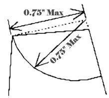
- Headboards shall not extend more than 0.75 inches from the head point.
- Parts of wire supporting the head of a sail that are less than 0.079 inches (2 mm) in diameter and not covered with sail material shall not be taken as parts of the sail.
Mainsail
- There shall be no more than four battens.
- If the luff is set in a luff groove and except as permitted by “Discontinuous Attachments” statement above, the “B” measurement and widths shall be taken to the aft edge of the mast spar.
- The “B” measurement and widths shall be taken to the fore edge of articulated flaps and/or fairings if they are used.
- If the sail has a double luff, the “B” measurement and widths shall be taken to the luff with the mast in place, or to the fore edge of the spar, whichever gives the greater dimensions, and the head point shall be taken at the aft edge of the spar.
Jib
- There shall be no more than three battens.
- If the sail is set on a luff spar, the “R” measurement and widths shall be taken to the luff with the spar in place or to the fore edge of the spar, whichever gives the greater dimensions, and the head point shall be taken at the aft edge of the spar.
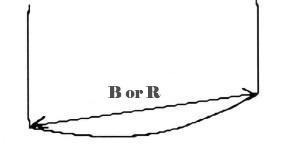
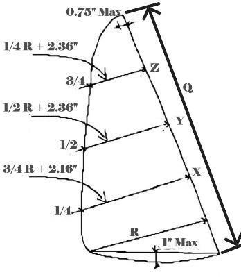
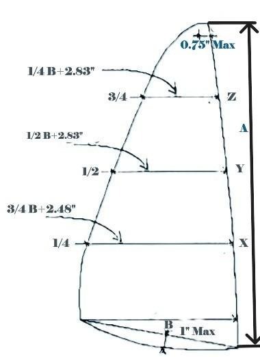
Sail Area Calculation
| Triangular Sail Area | Excess Area | |
| Mainsail | 0.5 x A x B | A x (2X + Y + 2Z) / 6 |
| Jib | 0.5 x Q x R | Q x (2x + y + 2z) / 6 |
Where: X and x are the excesses in the quarter widths
Y and y are the excesses in the half widths
Z and z are the excesses in the three quarter widths
Control of the Upper and Lower Leech Profile: The Template
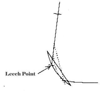
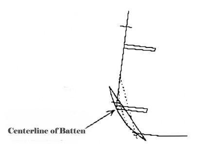
A template of 35.5-inch radius shall be used for this purpose. At the head, the template shall be placed to touch the aft head point and a straight line through the two nearest leech points. At the clew, the template shall be placed to touch the clew point and a straight line through the two nearest leech points.
If a leech point (diagram a) and/or a point where the centerline of a batten intersects the leech (diagram b) falls outside the template when positioned as above, the template shall be repositioned to either point so that neither point appears outside the template. When the template is positioned according to the instructions above, the leech shall not project outside the template.
Appendices
The Appendices are for information only and are not part of the class rule. Corrections or updates may be made in this section for clarity that are not considered to be changes to the official rule.
Appendix A: Historical Note (by Earl Boebert)
These rules impose a limit on the draft or keel appendage. This deviates from the Model Yacht Racing Association of America (MYRAA) rules, which lacked any such limit. Draft specification was never an issue in the free sail era as draft and appendages were automatically limited by the fact that you had to be able to sail your boat up to the shore to pole it on a beat. Since an R/C boat can avoid shallow water, the US VMYG had to do something to prevent “extreme” designs with deep keels, and so the draft/appendage limit was introduced.
Appendix B: Change History
June 2026
- Descriptive changes were made to the Introduction to accommodate the two new Classic subdivisions: C1 and C2.
- Section title heading weights updated for consistency and to allow two classic subdivisions to be included under first level section “Classic M Vintage Marblehead (period roughly from 1971 to 1985)”. Also, the sections under the subclasses (like “Design Formula”) were all changed to level 3 for consistency.
- “Movable” spelling corrected under “Prohibited” in the Traditional subclass.
- Items added to the definition list to support the Classic subdivisions. Also the list was alphabetized.
- “Classic M Vintage Marblehead (period roughly from 1971 to 1985)” was rewritten to include two Classic subdivisions.
February 2025
- A clarification was added under “Hull” to address removable keels.
- Definition of prognathous keel clarified to: “No portion of the keel appendage, including the lead, may project forward of any portion of the leading edge of the keel fin above” to match the definition in the V36 rule.
- A clarification was added regarding deck materials in the Classic subclass.
- A clarification to the Classic (1971 to 1985) subclass to add a maximum cross-sectional dimension for masts of 0.75 in.
- A clarification to the Classic (1971 to 1985) subclass rule to allow sail plans from the period. Specifically the following bullet was added:
- Sail specifications and measurements shall be as defined under “Traditional” and “High Flyer”. Different designs may be acceptable if they are original sails or it can be shown that they match exactly a sail plan that was in use during the “period”. A copy (photo) of the plan may be required.
- Updated the Sail Measurement Equation for image quality only.
- Labeled the Historical Note as Appendix A.
- Added this “Change History” section as Appendix B.
December 2022
- Added definitions section to the introduction including definitions for: Keel, Centerboard, Rudder, Skeg, Bilge-boards, and Leeboards.
- Added a clarification to the Traditional rudder rule:
There can be no more than one rudder.
- Updated “Minimum fin keel chord length shall be 5 in.” in Traditional hull rules to:
The minimum keel fin chord length is 5 in. No more than one keel fin is permitted. The keel must be attached to the hull underbody on the centerline. Neither the keel nor any part of it shall be movable (e.g., keel “trim tabs” are not permitted). Rudders may be attached to the trailing edge of the keel, in which case they are the single permitted rudder.
- Updated wording for Alternate Rigs under “Rig” from
Alternate rigs are permitted provided the sail area does not exceed 800 in2. Any such alternate rigs should have examples in design practices of the period.
to
Alternate rigs are permitted provided the sail area does not exceed 800 in2. Any such alternate rigs must have examples in design practices of the period.
- Added a clarification for aluminum masts under “Rig”.
“Round aluminum tubing” means: 1) a constant round cross section over the full length of the mast; 2) the tubing must not be slotted; 3) no external structure that creates a slotted sail track may be affixed to the mast. The diameter of the round aluminum tubing shall be ≥0.75 in. Note that traditional jacklines and lashings or loops of line may be used to hold and support the sail.
- Added slotted mast rule under Classic subclass rule.
Slotted masts are permitted, and there is no minimum or maximum cross-sectional dimension.
- Corrected spelling of “leech” throughout.
August 2019
- Updated Introduction section.
- Added Classic Marblehead subclass
- Defined subclasses by boat properties, not strictly by time periods. Added rough time periods for each subclass.
- Traditional Vintage Marblehead (period roughly from 1930 to 1945)
- High Flyer Vintage Marblehead (period roughly from 1945 to 1970)
- Classic M Vintage Marblehead (period roughly from 1971 to 1985)
- Minor wording changes for clarity throughout.
- Added Historical Note by Earl Boebert.