The Model Yacht is a published three times a year by the US Vintage Model Yacht Group
- Schooners and Scale News. by Harry Mote
- 2001 VM National Regatta and Museum Exhibit. by Thom McLaughlin
- The Yankee Jr. Project. by Earl Boebert
- Overlapping Jibs on Small Scale Model Yachts. by Earl Boebert
- Model Yacht Construction Over a Solid Form. by Ted Houk (1941) and Rod Carr (2001)

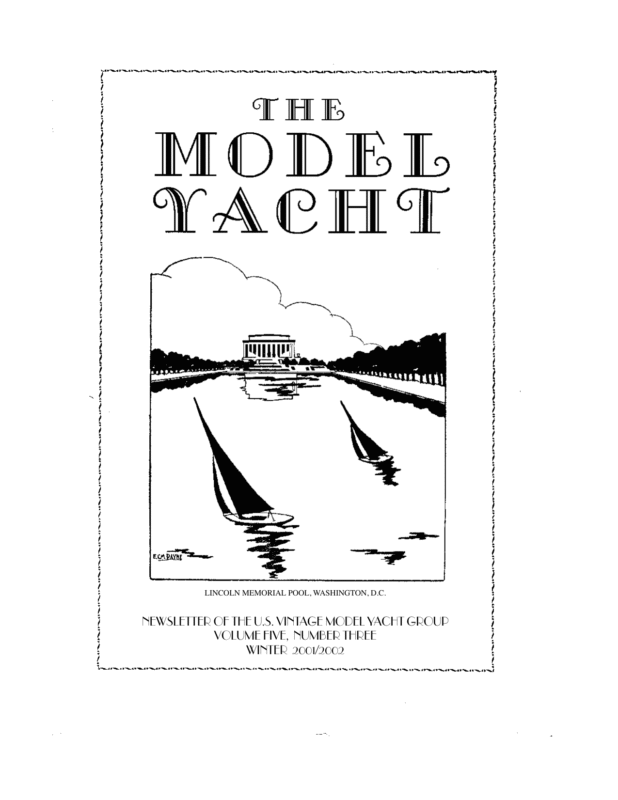
LINCOLN MEMORIAL POOL, WASHINGTON, D.C. NEWSLETTER OF THE U.S. VINTAGE MODEL YACHT GROUP VOLUME FIVE, NUMBER THREE WINTER 2001/2002
NEWSLETTER OF THE U.S. VINTAGE MODEL YACHT GROUP VOLUME FIVE, NUMBER THREE WINTER 2001/2002 Editor’s Welcome This is a special issue in many ways. Most obviously, it marks five full years of publication. Fifteen issues under our belt, and with a little luck many more to come. We are now the second longest-lived “pure” model yachting publication in the U.S., behind the AMYA Quarterly. It’s a cliche but true that we couldn’t have done it without you, our members, so let me take this opportunity to thank you for your support. The Winter issue is always one in which we try and print a major technical supplement to help you through the “building and dreaming” season. This time we have a special treat. Rod Carr has been working through the archives of the late Dr. Ted Houk, who (among other things) designed the “Rip Tide” and invented the three-axis self-tacking vane. Houk and other West Coast builders constructed amazingly light hulls (as light as 16 oz. for an M) in the era before fiberglass and epoxy. Rod has discovered and edited a previously unpublished manuscript by Dr. Houk on how this was done. In recognition of this effort we have dubbed Rod our first Guest Editor. Our thanks to Rod and to Dr. Ted Houk Jr. for making this material available. Finally, we present material on our current project centered around the “Yankee Jr.” design we documented a couple of issues ago. All in all, a special issue. Earl Boebert Ebbs and Flows The President’s Message About VMYG The VMYG is AMYA special interest group that promotes: 1) preserving, building, exhibiting, racing of older sailing model designs, and 2) study of the history of sport of model yachting. Vintage models are older designs with traditional appearance and built to sail. They include free sailed models, original designs converted to R/C and early R/C sailing craft. Vintage Membership Annual membership $20 fee is for three issues of VMYG newsletter “The Model Yacht”. (Please add $5.00 postage if outside North America). VMYG lifetime membership is $100. Members also gain access to technical assistance and vintage model plans. Our “how to” book and video package on plank-on-frame construction is available separately. To subscribe to our newsletter/services or to renew, please send check (payable to US VMYG) or $20 (or $100) cash to: John Snow, c/o US VMYG, 78 East Orchard Street, Marblehead, MA 01945. For inquiries about our activities, either call me @781-631-4203 or visit the VMYG Web Page at www.swcp.com/usvmyg Model Coordinators Vintage M (VM) Models: Charlie Roden: 732462-7483, cer@monmouth.com Traditional Sailing Craft/Scale: Harry Mote: 609660-0100, stryker@cybercomm.net Page 1
International A Class Models: Rod Carr: 425-8812846, RodCarr@CarrSails.com Canadian Representative US VMYG has new Canadian representative, Doug McMain, who got involved with VMYG through VM model building/racing activities. He requests other vintage modelers in Toronto and Canada contact him at: Doug McMain, 433 Old Orchard Grove, Toronto, Canada M5M 2G3; Phone: 416-782-4514 Email: d.mcmain@HydroOne.com UK Coordinator Graham Reeves has graciously agreed to act as our UK Coordinator, handling matters such as US/UK Vintage events and other dealings with the UK Vintage Group. Members wishing to contact him can at Graham Reeves, Arcadia, Pool Close off Chapel Street, Welford on Avon, Warwickshire, England CV37 8QB; Phone/Fax: 01789 751800 Australian News Our good friend and contributor Steve Crewes has been appointed the Historical Officer/Archivist of the Australian Radio Yachting Association. Steve can be contacted at Steve Crewes, 2 Dunkeld Ave., Hurlstone Park, NSW 2193 Australia; Phone: 02 9558 5675, Email: funcrewes@dingoblue.net.au I’m sure all our members join me in congratulating Steve on his appointment. 2002 Activities 1st WoodenBoat School Model Course – June 16-22 Brooklin, ME; Six-day course on building plank-on-frame vintage model yacht. WoodenBoat School – 207-359-4651; VMYG Contact – Thom McLaughlin 813-251-6919 WoodenBoat Show – July 12-14 Rockland, ME; Vintage racing class/sailing craft model displays and demos with extensive exhibits of full-size wooden sail/power/rowing boats. Includes two other events: Atlantic Challenge, international races for rowing boats, and Watercraft Challenge, racing/display competitions for classic wooden boats. Volunteers & models welcomed. VMYG Contact – John Snow 781-631-4203 3rd Annual Mystic Model Yacht Regatta – July 30August 4 Mystic Seaport, CT; Six AMYA class championships: J & Soling 1M nationals plus EC-12M, ODOM (2) & Star 45 regionals, with six-day indoor model yacht exhibit. Volun- teers and models welcomed. AMYA Contact Greg Vasileff 860-455-9939; VMYG Contact John Snow 781-631-4203 4th San Francisco M Class Free Sail Invitational Regatta – August 10-11 Spreckles Lake, Golden Gate Park, San Francisco, CA; Old-style, freesail racing of M Class models to the San Francisco Restricted Rules, with practice beginning August 8. SFMYC Contact – Jeff Stobbe 831-475-6233 International Yacht Restoration School “Family Day” – August IYRS, Newport, RI; VMYG model display with IYRS open house/exhibits, harbor excursions, children’s activities.IYRS Contact – 401-848-5777; VMYG Contact – John Snow 781-631-4203 20th Annual Antique & Classic Boat Festival – August/September Boston, MA; VMYG exhibit booth and R/C vintage model sailing demos. Volunteers and models welcomed. VMYG Contact – John Snow 781-631-4203 2nd WoodenBoat School Model Course – September 8-14 Brooklin, ME; Six-day building course for Detroit Schools vintage model yacht using lift method.WoodenBoat School – 207359-4651; VMYG Contact – Alan Suydam 248476-3017 Eighth National Vintage Model Yachting Days Regatta – September 21-22 Spring Lake, NJ; R/ C VM model racing and display competitions. Marbleheaders MYC/VMYG Contact Charlie Roden 732-462-7483 & cer@monmouth.com Traditional Sailing Craft/Scale Model Regatta – September 28-29 Calvert Maritime Museum, Solomons, MD; VMYG national race/display competitions for R/C traditional sailing craft and schooner models. All traditional sailing models welcomed. Solomons Island MBC Contact – Buck McClellan 410-326-6019 & shadow195413@aol.com VMYG Contact – Harry Mote 609-660-0100 Annual Free Sail Model Regatta – October 13 Red Beach, Menemsha Pond, Martha’s Vineyard, MA; Children/adult races with scratch-built, free-sailed wooden models one meter long and under.Regatta Contact – Spa Tharpe 508645-3688; VMYG Contact – John Snow 781631-4203 Page 2
Vintage Etcetera 2001 Vintage Model Yachting Days Regatta Note of appreciation to Thom McLaughlin and his crew who conducted top-notch 2001 VM national regatta in Tampa November 3&4. Racing was on tidal river in Tampa. Event was staged from park next to Henry Plant Museum with its pond yacht exhibit. Topthree R/C VM skippers were Alan Suydam, Ned Lakeman and Charlie Roden. VMYG participation in exhibit-type venues has really provided our sport with more exposure than could ever be realized at pondside. Susan Carter, Curator of Plant Museum, estimated their pond yacht exhibit coordinated by Thom McLaughlin was seen by 40,000 people during its run in 2001! John Snow Schooner and Scale News Bluenose The new addition to Hartman’s RC modeling catalog is a fiberglass hull for the schooner “Bluenose.” She is 51-1/8” on deck, 8-1/4” beam and has a bare hull weight of 1-3/4 lb. The completed boat would not qualify in any of the USVMYG 50 inch schooner classes, but would sail in the open class. Bare hull is $160, plus shipping. Hartman does not plan to create a complete kit, or any components, for this model. Plans of Bluenose are available from a number of sources. One of them is Taubman Plans Service International, 11 College Dr., #4G, Jersey City, NJ 07305. Bluenose plans (EIS-001) include five large sheets, scale 1/4” = 1’, for $80, plus $7.50 shipping and handling. Traditional Scale Sail 2002 Two Fiberglass Schooner Hulls Now Available Hartman Fibreglass RC is now producing two fiberglass schooner hulls for radio controlled sailing, one of them as a complete kit. Malabar I The “two-masted scale schooner,” as described in Hartman’s catalog, has been available for a few years and Hartman has sold over 15 of them to date. It is 48-1/2 inches on deck and qualifies in the USVMYG 50” schooner rules as a kit schooner. It is available as a bare hull or complete kit with completion plans. Bare hull is $172.70, plus shipping and the complete kit is $238.70, plus shipping. This fiberglass hull/kit is based on a model of the John Aldendesigned “Malabar I” that was built by Swede Johnson of the San Diego Argonauts. Hartman built the mold for producing fiberglass hulls from Swede’s hull lines. The kit includes an 18-lb. lead keel casting, three construction drawings, copies of several construction photos, and other components. The bare fiberglass hull weighs 2 lb., 9 oz. The model is completed by constructing a wooden deck, completing spars, rigging, etc. This “Malabar I” model should sail very well. The USVMYG Traditional Sailing Craft Scale Models regatta will be held at the Calvert Maritime Museum, Solomons, Md., September 21-22, 2002, hosted by the Solomons Island Model Boat Club. Contact is: Buck McClellan, P.O. Box 335, Solomons, MD 20688, 410-326-6019, shadow1954@earthlink.net. Look for regatta entry form in the Spring/Summer issue of The Model Yacht. Regatta events will include competition for 50” and other schooners, skipjacks and other traditional sailing craft types. The Original For Hartman’s “Scale Schooner” Page 3 VMYG Schooner Business As reported in the Fall, 2001 issue of The Model Yacht, four of the 50” schooners that participated in the Traditional Scale Sail Regatta at Mystic Seaport Museum, Mystic, Ct., last August had fins and bulbs. Two of these schooners were of the owner/ builder’s design.
Current USVMYG schooner rules, Sub-Category B, allow keel fins and bulbs to be added to plank on frame, 50 inch scale models of real schooners designed or built before 1940. In the last issue of The Model Yacht we raised the question: “Should this part of the rule be amended to allow owner/builder original designs, as long as they are traditional, fullkeel schooner in hull form?” and asked for comments. We had one response to the question. It was from a sailor who already complies with SubCategory B rules. We did not hear from any owner/builders of original traditional schooner designs, so we will make no changes to the rules at this time. In the future, as in the past, we will accommodate the interests of owner/builders who participate in regattas by allowing them to compete in a way that is agreeable to other sailors at the event. Harry Mote But at the time of this writing the regatta is past, the exhibition’s loaned boats and materials are packed in crates, and all is a recollection of experience. Hence this regatta and exhibition report relies on the tidal flow of memory – which is perhaps how we actually perceive events. What follows will be written as such. I remember: – John Snow’s superbly restored Roy Clough Marblehead with its beautiful black hull and pine deck and sail number of M1. It was a delight to uncrate, to view for those many months of the exhibition, and sad to recrate for its journey back to its Marblehead home. – Al Suydam’s second version of a Cheerio I that he sailed in the regatta to first place overall and received the Construction Trophy for building. – The many close finishes between the boats of Al Suydam, Ned Lakeman, and Charlie Roden. – The first national regatta participation of Doug McMain who traveled from Canada to sail his lift method built Cheerio I which constantly improved its performance over the weekend. – Joyfully watching John Snow sail my 1947 Ains Ballantyne Arrow to a commanding lead until it’s sail winch suffered terminal failure. The 2001 VM National Regatta and Museum Exhibit November 2-4, 2001 saw the annual Vintage Marblehead National Regatta occur in Tampa, Florida. The regatta sailed for three days on the Hillsborough River, with the Plant Museum over the shoulders of the participants. In the 1930’s the Tampa Model Yacht Club sailed in the Davis Island Yacht Basin, just a mile further down the river. From March to December of 2001 the Plant Museum was the sight of an exhibition of examples of pond boats, images, and supporting paper (books, magazines, letters, and postcards) from 1900-1940. The Plant Museum is located in what was the Henry B. Plant Hotel. It opened in 1891, a 400 room Victorian architectural treasure capped by minarets and crescent moons. The building is on the National Historic Register, part of ‘exotic’ Florida, highly visible, and all of which insured that approximately 40,000 people saw the exhibition during its installment. – Watching Earl Boebert, out of the corner of my Race Director’s eye, graciously and gleefully fielding questions from visitors after his loaned Cheerio III caught the same disease as John’s loaner boat. (Sorry guys, I really would have rather been able to perform repairs than be RD!) – Smiling at what was probably 350 visitors to the regatta over the three days to watch pond boats sail with the city of Tampa across from them on the river. For me it was a wonderful urban landscape painting. – And many continuing thanks to my many friends who were cajoled into serving as the regatta crew; most of whom, although they may have raced full size boats, this was their first experience of pond yacht racing. – I could give you a complete run-down of final finish standings, but that’s probably not why we sail. I’ll just pass on that everyone received a trophy which were framed post cards from 1910-1940 of pond boats; each Page 4
image being specific to the recipients past or present sailing home. So that’s wonderful memories, and now a new year is here which will bring another national regatta to Spring Lake, NJ. I am looking forward to seeing all of the above people (and more) there again. And watch out for John, he will be sailing his own boat that go round and my prediction is that he will leave with the first place trophy there! Thom McLaughlin Preliminary Thoughts I’m trying to engineer a boat that could be made by somebody with no experience and no source of advice; something that could finished in a half dozen weekends or so. The time objective, more so than the cost one, determines a lot of the choices. Hull In order to simplify the trimming process, the hull is molded complete with a hollow fin and loaded with lead shot, distributed between compartments until she trims out on the LWL. Rig The mast and spars will be made from 5/ The Yankee Jr. Project “Yankee Jr.,” which we described in Vol. 5 No. 1, has a great deal going for it. The 36 inch size is convenient to transport but still large enough to look reasonable on the water. The full keel hull handles weedy ponds exceptionally well. And finally, she’s a very handsome boat. The one problem lies in the construction of the hull. Full keel boats are notoriously difficult to plank; a carved hull is theoretically easier to shape properly but difficult to get light enough, especially with a radio. The obvious choice is fiberglass. At some point it occurred to me that we lack a simple beginners boat of traditional design. The “plug” and mold could be used to produce multiple hulls, and the USVMYG could offer a book and a video to help the beginning skipper. Mike Kelley (www.pondboats.com, 1567 Spinnaker Dr. #203 Ventura Ca. 93001; 805-641-1215) agreed to do the hulls. So now we have a project for 2002! 16 inch aluminum tubing. This is available from a standard hobby shop metal supplier in 36 inch lengths. The mast will be spliced with a wood dowel where the stays attach. Standing rigging will be simple, as on the original: combination fore/jib stay, backstay and two side stays. Sails Based my experience in making spinnakers, the sails will use kite maker technology to avoid sewing. Sails will be laced to the mast. Radio The radio rig will follow the ideas of the original article. An ordinary servo will be converted to a drum winch, with all running rigging up on the deck. An Invitation I hope to include an appendix in the construction manual giving ways to make a little more elaborate boat, such as how to plank a cambered deck, etc. Members wishing to contribute to this section can contact me at any of the editorial addresses. The Master Form for the “Yankee Jr.” Hulls Page 5 Earl Boebert
35 26.5 20 19 18 16 15 Main Winch Auxilary Fairlead Line Fairleads Jib/Winch Fairleads (1” Centers) Fairleads (2..5” Centers) (6” Centers) 8.5 3 Mast Staysail Jib Attachment Attachment Winch Drum Staysail Fairleads (3” Centers) Jib Starboard Jib Sheet (Pulling) Stays’l Combined Jib/Winch Fairlead Starboard Staysail Sheet (Pulling) Starboard Attachment Point Port Sheets (Slack) Port Attachment Point Winch Line (Dotted) Tension Block Mainsheet Block on Boom Starboard Attachment Point Main Fairlead Port Attachment Point Auxilary Fairleads Page 6
Overlapping Jibs on Small-Scale Models • The long, lean hull with its graceful overhangs Impressionistic Scale • The tall main sail. One of the things I dearly wish to do with the “Yankee Jr.” hulls is build a “scale” sailing model of the original “Yankee.” John Black properly described his design of “Yankee Jr.” as an adaptation. That is, he took the basic lines and sail plan of “Yankee” and adapted them to the entirely different physical regime of a 36” sailboat. With regard to the hull, he kept the form of the canoe body and deepened the keel to improve the righting moment. What he did to the sail plan was more interesting. He reduced the proportions of mast height and fore triangle dimensions to the hull — the mast is 93% as high as a scale mast for a 36” model of “Yankee.” This did not reduce the area enough, so he shortened the boom. The effect, whether by accident or design, was to make the rig appear taller by increasing its aspect ratio, that is, by making it proportionately “narrower.” But the greatest variance from the original was in the foresail, where he used, as we must in a simple sailing model, a single jib “clubbed” to a boom. • The “double headed” rig, with a loosefooted jib overlapping a loose-footed staysail, which in turn overlaps the mast. Now when we consider a scale sailing model we immediately run up against the inexorable laws of physics, which dictate that the smaller you make a model the less able it will be to carry sail. If one attempts a “literal scale” model, that is, one in which all dimensions of hull and sail plan are reduced to the same proportion, the result will be a boat that will sail in only the lightest of breezes. The hull form can come from Black’s adaptation, because the modifications are below the water line and not immediately visible when she is sailing. The apparent height of the rig we can deal with using his trick of increasing the aspect ratio. The remaining sticking point is the double headed rig. The Charters System The rig I came up with is based on that of Andrew Charters, whose work was described in our last issue by Harry Mote. As Harry said, it takes a bit of study. I finally resorted to constructing a full-size mockup of the rig and playing around with various locations of one thing and another. I recommend this process, as it saves a lot of extra holes in your final deck. The Charters system is based on the notion of double-sheeted jibs and mains operated by a Our objective, instead, is to develop a design which, when in its element on the water and viewed from pondside, would cause an informed observer to say “That looks just like a J boat.” For lack of a better term I will call such boats “impressionistic scale” to differentiate from the “literal scale” of display models. What we give up in literal accuracy we gain in other areas: the set of the sails, the angle of heel, the bow cutting the water, the trail of the wake behind her. The trick in impressionism is to capture the essence of the object being represented. If we study the pictures of the J’s, we quickly see that there are three things that define their essential form: 22.5 32 21 16.5 7 11 Foresail Dimensions for a “Yankee Jr.” Hull Page 7
sail winch. Depending on the position of the winch line, one of the sheets is active (pulling) and the other is slack. When tacking, the winch line is “overrun” and the result is that the pulling and slack sheets are reversed. This will be explained in more detail below. Sail Dimensions The sail dimensions are given in the diagram on the previous page. As with the mainsail, the aspect ratios of the sails are slightly increased to give the appearance of a taller rig. Deck Fittings The position of the deck fittings is shown in the top diagram on page 6. The fairleads in the mockup are all screw eyes; in a proper model they would be single and double blocks. The numbers in the top row are the distance in inches of the fitting aft of the stem. Sheeting The second two diagrams illustrate the foresail and mainsail sheeting, separated for clarity. There are six sheets: • Port and Starboard Jib Sheets • Port and Starboard Staysail Sheets • Main Sheet • Winch Sheet Operation of the Foresail Sheets The top diagram shows the foresails close hauled on the port tack. The starboard sheets are pulling because their attachment point is forward and the port sheets are slack because their attachment point is aft. As the winch rotates counterclockwise, the two attachment points move toward each other. The slack sheets become less slack, and the pulling sheets permit the sails to sheet out. At some point, 5” forward of the furthest aft point on “Yankee Jr.,” the foresails are sheeted out as far as they will go. There is still 10 1/2” of winch travel left. This is used to “swap” the pulling and slack sides when tacking as follows: Continual counterclockwise rotation of the winch drum will cause the two attachment points to pass each other in the middle, with the port side point now aft and the starboard side point forward. As this happens, the pull on the port side sheets will cause the clews of their respective sails to “crawl over” the staysail stay and mast respectively, and when the winch sheet has traveled enough the rig will look just like the diagram but with the sides reversed. Note that after “swapping” the operation of the winch drum is reversed: counterclockwise rotation now sheets in and clockwise sheets out. This is handled simply by having the skipper throw the reversing switch on the sail control of the transmitter. Operation of the Main Sheet The winch sheet starts at the winch drum immediately aft of the mast, runs abeam and slightly aft to the combined winch/jib fairlead, then aft to the winch sheet fairlead and around a tensioning block, and finally back similarly to the winch drum. It is shown as a dashed line on the diagrams. There are two attachment points on the winch sheet as shown. They are arranged so that when the port attachment point is hard against the combined fairlead, the starboard attachment point is hard against the winch fairlead aft. This maximizes the travel of the winch sheet to the distance between these two fairleads; 15 1/2” in the case of “Yankee Jr.” The three operating sheets on both sides are attached to the same attachment point, and then run through their respective fairleads as shown. The Charters system uses multiple winches for sail control, which would be clearly difficult in a 36” boat with only 6” or so maximum beam. So it was essential that a method of “synchronous sheeting” be developed. After much head scratching and the expenditure of a great deal of pencil lead I came up with the arrangement shown in the lower diagram. The main sheet is reeved through the two auxiliary fairleads (placed at 50% of the winch sheet travel) and up through a fairlead to a block on the boom mounted straight above the mainsheet fairlead. As noted before, when the foresails are sheeted in the two attachment points become further apart and as they are sheeted out they become closer together. This action, with the main sheet reeved as shown, causes the amount of mainsheet between the main sheet fairlead and block to increase or decrease just as we want it to. When a “swap” occurs the dia- Page 8
gram will reverse just as it did for the foresail sheets, but this makes no difference to the geometry of the main sheet. You have to look at it a couple of times to convince your self it works but I assure you it does. Sheet Adjustment Another problem that occupied me was that of adjusting the sheets. There are two sets of adjustments that have to be made: the position of the attachment point and the length of each sheet relative to the others on the same side. Simple solutions for the foresails, like looping a sheet through a bowser, have the potential for fouling the stay or mast when a “swap” occurs. The solution I intend to try is a “multiple bowser.” This is a small block of Lexan with holes drilled and sheets reeved as on a conventional flat bowser, except four lines across. It would slide on the winch sheet like a jackline, and then the other sheets would be adjusted off it. Final Remarks Well, that’s it. As I said before, these ideas have not been tried out on the water, but it sure would be nice if some brave soul tried this on one of those big AMYA J Class boats and had her looking “just like a J.” Earl Boebert Contact: Don Seales HC 81 Box 1945 Searsmont, Maine 04973 Email donnann@mint.net Pete Peterson Email Pete Peterson, master builder of Spring Lake NJ and star of our video on spiling planks, can now be reached on the Internet by people who would like to purchase one of his boats or have one made. His email is: sawdustpete@hotmail.com Turnbuckles Member Geoff Laverne reminds me that small brass turnbuckles are used by the 1/4 size scale airplane people to tension rigging on biplanes and such. An afternoon spent searching on the Web turned up several sources for brass turnbuckles made by Proctor and Graupner among others, listed by Hobby Lobby and Tower Hobbies. Model Expo, the static model ship people, also have operating brass turnbuckles in a variety of sizes. All of these are the size of the small A.J. Fisher ones or smaller. French Vintage Group There is now a French Vintage Group. The contact point is: Roger Baehr, President, Club Vintage Boats Chemin Des Haros 14130 Le Brevedent France Bits of Oakum Suggestions Wanted Cheerio Hulls Available Don Seales wanted to let members know that he is now offering Cheerio I hulls in Acrylic modified Epoxy resin. The hulls are from a mold made from a boat built for Bud Conners and Art Hart has one of these hulls that showed up at the Woods hole meet this past spring. Don is offering the Hulls for $125.00 bare and manuals go with it. He also offers boats at any stage; prices on request. Murray Barber is a professional ship modeler specializing in wooden model yachts, static as well as R/C. He is trying to develop an R/ C vintage model yacht built of wood, with modern materials and techniques, and has asked for suggestions on what design to pick. I suggested a VM based on “Detroit News;” others of you may have other ideas. Murray can be reached by email at dragonwork@hotmail.com Page 9 Earl Boebert
the eyepiece of a colonoscope while the business end probed the internal construction and crevices of a 7-foot long A-boat. Only Dave would have thought of that. Having assisted in some of the restoration projects, I can only say that my workshop is going to be a good deal emptier without him. But I would expect that he is already organizing a Vintage event in a place where the winds are steady, the air is warm, and the batteries never need charging. Rod Carr The Model Yacht is published three times a year by the U.S. Vintage Model Yacht Group. Copyright 1998,1999, 2000, 2001, U.S.V.M.Y.G. Reproduction for noncommercial purposes permitted; all other rights reserved. Editorial Address: 9219 Flushing Meadows NE Albuquerque NM 87111 Email: boebert@swcp.com Phone: 505 823 1046 David Stedman 1938 – 2001 The Vintage Model Yachting movement lost one of its major supporters on December 22, 2001 with the passing of David Stedman of Kirkland, Washington. David entered the Vintage arena with the restoration of the Marblehead “Arrow,” a boat of somewhat mysterious birth, which had captured the first MYRAA DX Class National Championship in 1951. Having whetted his appetite for Vintage wood, he then pursued Allan Rumpf and arranged the purchase and restoration of the Gus Lassell A-Class boat “Angella. “Though a beginner at the transmitter, he relished sailing “Angella” with any other boat that could be enticed on to the water with her. His favorite story concerned an inadvertent running down of his son Michael’s little 30” Victoria, whereupon Mike looked at his father and moaned, “You big bully!” Officers of the U.S. Vintage Model Yacht Group: President: John Snow Eastern Vice-President: Ben Martin Midwest Vice-President: Al Suydam Western Vice-President: Dominic Meo, III Southeastern Vice-President: Thom Mclaughlin Traditional/Scale Coordinator: Harry Mote Vintage M Class Coordinator: Charles Roden A Class Coordinator: Rod Carr U.K. Coordinator: Graham Reeves Canadian Representative: Doug McMain Historian: Earl Boebert Archivist: Jim Dolan Dave was a watchmaker of unusual talent, and that transferred into the work he carried out on the model yachts he owned. He made fittings for the restored boats, and was called upon to fabricate the precisely machined keel width gauges employed by the East Coast 12 Meter Class. Always one to find new uses for old tools, I once saw him squinting through Page 10
Model Yacht Hull Construction Over A Solid Form rarely weight less than 32 ounces. Double planked hulls have never been known to have split open at the seams, or to be crushed during competition. Guest Editor’s Note The following describes the construction of a solid hull form, built in a combination of vertical and horizontal layers in the Bread and Butter tradition. The form is used to set the shape of two layers of thin planking stock in a method which is now known as “cold molded” construction. A 1/2” slot, referred to as the “centerpiece” provides for the insertion of the keel/backbone of the finished yacht prior to planking. This description is taken directly from Dr. Houk’s handwritten and typed manuscript and hand drawings. Limited editing provides for clarity of meaning. Dimensions given are applicable to a form for Fig. 1 producing a Marblehead (50/800) sized model. For larger or smaller sized models adjust the lengths accordingly. 1” waterline lifts are recommended for models of all sizes. Rod Carr The Vertical and Horizontal Plank Method of building was devised with the assistance of George Pocock, internationally famous builder of racing shells. The first yacht built by this method was the Marblehead “Bobby” which proved herself by enduring eleven days of Divisional and National Championship Competition in Berkeley, California 1938, under extremely rough weather conditions. Since then, many yachts along the Pacific coast have been built the same way, including the 1941 M-Class National Champion “Humptulips”. Its advantages are, maximum strength at minimum weight, water tightness, ease of construction, and accuracy of duplication when several hulls are built over the same form. It helps advance the sport of model yachting in a community for a club to own several forms so that successful yachts that can be easily and accurately duplicated by beginners. Weights of M-Class hulls built by this method average from 16 to 24 ounces, whereas the lightest Bread and Butter hulls First, a solid block form is made as follows.1 Select some straight, fine, soft, slash-grained Douglas fir, free from knots with a length 50”. Have this planed accurately to 1.00” thickness, or whatever thickness is indicated by the waterline spacing of the design selected. Stack up several layers of the lumber during planing and insist that 4 or 6 layers measure exactly 4” or 6” thick as the case may be before taking delivery. Have both edges run through a jointer so that they are square and straight. Have one plank planed to exactly 1/ 2” for the centerpiece. At the same time have a piece of fine grained clear sugar pine about 2” wide planed to 1/2” thick. This piece of pine will serve as the backbone of the finished yacht. On a piece of 1”x1” lumber, the length of the boat (50”), accurately mark the section spacings as indicated on the design with a knife. Carefully square these section lines across the piece and number them to correspond to the design. This piece will serve as a master section pattern for laying out the sections on the planks used for building the form. Lay the first plank on the bench and place the master section pattern alongside. With a knife and a square transfer the section lines onto the plank and number them. Repeat this procedure for each plank to be used in the construction of the form including the 1/2” thick centerpiece. On the design’s profile plan strike a datum line parallel to the waterline and 1.0” above the highest waterline.2 (See Figure 1). This datum will represent the base of the solid form. In transferring lines from the design to Page 11 1. Dimensions given are for a typical Marblehead (50” LOA) model. If the method is applied to a different class, adjust the outside dimensions of the planks accordingly. – T.H. 2. The words “top, bottom, upper, lower” etc., refer to positions on the finished yacht in its normal, upright position, remembering that most of the construction work is done with the yacht upside down. – T.H.
to the centerpiece of the form. Fig. 2. the form, measure to the nearest section waterline, this will minimize error due to shrinkage or stretching of the blueprint. The datum line will locate the bottom, straight edge of the centerpiece of the solid form. Fig. 3. Now lay out the centerpiece. After determining the thickness of the transom, say about 3/8”, mark the inside of the transom on the design and transfer this line to the centerpiece of the form. Likewise determine the position and fore and aft thickness of the stem piece. To do this lay out a buttock, 1/ 4” from the centerline on the waterline plan. This will be the half width of the centerpiece and backbone. Set a divider at 3/32” (the thickness of the planking).1 With a leg of the divider on the 1/4” buttock and the other leg on the side away from the centerline, run the dividers along the 1/4” buttock until its other leg rests on a waterline. This represents the fore and aft position of the intersections of that waterline and the 1/4” buttock on the form. (See Figure 2) Transfer this point and the corresponding points for the forward waterlines on the profile plan. Lay a straight edge on the profile plan so that it rests at least 1/4” aft of the nearest points on the 1/4” buttock of the block form. This line represents the after edge of the stem piece (Figure 3) and can now be transferred Locate the positions of the top surface of the backbone on the profile plan. Mark the 1/4” buttock on both sides of the centerline using the section plan (Figure 4). If the plan shows the lines of the canoe body as well as the keel, use the section lines of the canoe body as follows. If it is not shown, complete the design by drawing in the canoe body intersection with the centerline. This can Fig. 4. be done easily by placing a spline on each section of the section, letting it fall naturally to the centerline of the hull, ignoring the curve of the garboard.2 Transfer the points of 1. The 3/32” allowance for planking represents the net planking thickness remaining after one layer of 3/64” vertical planking and one layer of 1/20” horizontal planking is glued down and faired. – T.H. Page 12 2. At the time Dr. Houk wrote this the Marblehead Class rule required a minimum 1” radius of the garboard, where the canoe body intersected with the keel. The requirement was dropped in the early 1940’s. The USVMYG VM Class rules require it, while the SFMYC Restricted Rules do not. – Ed.
intersection of the projected sections and the centerline to the profile plan. Spring a batten through these points and through the profile fore and aft of the keel. Draw the profile of the canoe body. Any irregularities may then be faired and the points adjusted on the section plan. Measure perpendicularly up from each section line on the canoe body 3/32” to a point on the 1/4” buttock line. The 3/32” allows for thickness of planking. These points represent the 1/4” buttock line on the form.1 All the points on the 1/4” buttock line of the form are now determined. Now measure 3/32” up from the 1/4” buttock line of the form on each section to allow a little thickness in the backbone. A line through these points will represent the top edge of the backbone. Transfer this line to the centerpiece of the form. Draw in a triangular knee or brace between the stem piece and the top of the backbone. Transfer this data to the centerpiece of the solid form. Using a band saw set accurately to 90 degrees saw the profile of the backbone out of the centerpiece. Cut slowly and carefully to the lines representing the after edge of the stemhead, the after edge of the triangular knee, the top of the backbone and the forward surface of the transom. The centerpiece, minus the space needed for the backbone to occupy is now ready. Retain the piece sawn from the centerpiece to use as a pattern for subsequent backbones should more than one hull be made on the form. Now configure the centerpiece to receive the keel bolts. Mark the lines representing the keel bolts, and saw out a square window in the centerpiece by cutting about 1/2” forward of the forward keel bolt location, and about 1/2” aft of the after keel bolt leaving about 1 1/2” of wood inside the datum line and the top of the backbone. Drill through the centerpiece for the keel bolts, starting two holes from the datum line and from the line of the top of the backbone. Be sure the holes are absolutely square and in line. Start a piece of the material used for the keel bolts through one hole and see that it can be easily manipu1. That is, the location of the inner surface of the planking. The foregoing work was required because hull lines plans are drawn to the outside of the planking, whereas the construction form we are building represents the inside of the planking. – T.H. lated all the way through the centerpiece. For a Marblehead two 3/16” high test steel bolts should suffice. Make them long enough to run from the datum line to the bottom of the keel with enough to spare to allow nuts to be attached. Take a piece of the 1” stock and with the one edge representing the datum line, lay out the entire length of the 1/4” buttock and the forward surface of the transom. Cut out the curve so plotted with a band saw and plane it down to the middle of the marked line. Lay the board down on another 1” plank with the datum lines and section lines carefully matched. Use a fine hard pencil and mark out the second piece for use as the opposite side of the form. After sawing out the second plank, clamp it accurately to the first one and accurately surface the second plank to match the first. It is not necessary that the two have their planed edges square as they will be cut away later, but the surfaces must match on the edges that are nearest to the centerline of the form. We now have one centerpiece and two buttock lifts completed. The remainder of the form will be built by stacking planks horizontally on either side using the waterline data as reference. By using this procedure the builder avoids wide open unmarked spaces in his form, making for more accurate construction. It also reduces the amount of material that has to be cut away, thereby saving time and labor over building the entire form on the buttock plan, or waterline plan. The next lift to be built is the top one, its top surface representing the datum line and its bottom surface representing the highest waterline. Note the point on the profile plan where the sheer cuts the highest waterline. Measure about 3” aft of this point. This will be the location of the after end of the top lift and allows a short piece of 1” stock to be use in its construction. Transfer the deck line to this piece using the 1 1/4” buttock as a base line and subtracting 3/32” from each section to allow for the thickness of the planking. In the case of tumblehome use the greatest width at each section, be it the highest waterline or the deck line. An easy way to transfer the waterlines to the lifts is by the use of a paper ticking or “tick” strip. Lay the edge of a strip of paper on the top waterline of the section. Mark the center- Page 13
line, the 1 1/4” buttock line and the intersection of each section with the top waterline. Measure out 3/32” from the 1 1/4” buttock line to allow for the thickness of planking. Holding the paper edge between thumb and finger of the left hand so that the 3/32” mark is over the edge of the top lift, move it along the edge of the plank and mark each section with the point of a knife, cutting right down through the edge of the paper into the board, thus avoiding the possibility of distortion of the initial cut mark by a slant- Fig. 5 ing grain of the wood. Lay out the waterline ending on the centerline, with the help of another piece of 1” wood placed against the one being marked to hold up the ends of the spline. Remember to allow 3/32” for the thickness of the planking. In determining these endings, an easy is to set the divider at 3/32” and run it along the waterline until the other leg touches the centerline. There sharp curves are found in the waterlines, it is advisable to lay out the points where the waterline intersects with the two inner buttock lines using the 3/ 32” set divider in the same manner as with the centerline. Spring a batten through all the points marked and draw the edge of the top lift. Saw out as before and similarly make a piece for the opposite side of the boat. All edges of the top lifts and any other lifts with portions above the sheer line must be perfectly square. In a similar manner construct the remaining lifts. Use a new tick strip for each lift to avoid confusion. In the lower lifts the forward surface of the transom will serve as the after end of the lift. Remember to use the widest waterline where tumblehome appears in any lift. In the lower lifts, where the sections cross the waterlines at a more acute angle, it will be found inaccurate to allow for the thickness of the planking on the waterline plan. Here the allowance for planking must be determined by dropping a perpendicular 3/32” from the section on the section plan to the waterline using the dividers as described before. The new point on the section plan is then transferred to the waterline plan. Having completed sawing and planing the edges of all the lifts, the solid form is now ready to be glued up. Use any good glue, water proof or otherwise, since the form is not subject to water.1 First apply glue to both surfaces of the centerpiece and to the marked faces of the 1 1/4” buttock lifts. Nail these together with large finishing nails, taking care that all the section lines match and that the datum lines are even with each other. A square laid across the datum line edges and up the sides of the buttock lifts will assist in making this adjustment accurate. Be sure the nails are not placed so near the edges of the material that they will be struck by the carving tools used in final shaping of the form. Finishing nails are used so that they may be countersunk in case they are accidentally encountered in carving. A spacing of 3 or 4 inches between nails is sufficient. Be sure however that all the edges of the wood are well approximated and squared together tightly. Now, placing the datum line downward on a flat surface, apply glue to the straight edge of the top lifts and the corresponding surfaces of the buttock lifts. Toenail the top lifts to the buttock lifts with large finishing nails, make sure that the lifts do not slip and that they are square with the buttock lifts. Now apply glue to the bottom surfaces of the top lifts and to the adjacent surfaces of the next waterline lifts. Also apply glue to the straight edges of the next-to-top lifts and to the corresponding surfaces of the buttock lifts. With the form upside down, place 1” blocks under their free ends to prevent them from sagging. Again, toenail into the buttock lifts and into the top lifts taking special scare that the free end is everywhere exactly 1” below the datum line. Proceed the same with the remaining lifts, always making sure that the accurately marked face is on it proper corresponding waterline level and that the nails are well hidden from the carving tools. A safe way is to mark the next waterline in roughly by tracing it from the adjacent lift and keeping the nails about 1/4” inside of that line. Page 14 1. Modern adhesives such as West System Epoxy are highly recommended for this application. – Ed.
After the glue is dry start carving the form. (Figure 5) The free portions of the buttock lifts aft the top lifts are convenient to fasten the form in a vise. If a second vise is available, the after part of the form may also be clamped down making for even greater stability. Firm fixation of the form and a solid work bench make short work of carving up. The builder can then be as vigorous as he wishes with chisel, drawknife, plane and sanding board without knocking his work all over the shop. Now prepare section templates to assist in the carving of the form.1 If errors due to shrinkage and stretching of the blueprint are present, prepare a duplicate of the section plan on 10 x 10 paper, measuring to the nearest waterline or buttock on the blueprint for locating points on the sections. Lay a piece of 1/8” or 1/4” plywood or box lumber under the accurate section plan. With the dividers set at 3/32” to represent the thickness of the planking, prick through to the wood below keeping one leg of the dividers on the section line and the other leg inside the line, perpendicular to the section line. This transfers a parallel line of dots to the wood, the outer line representing the outer skin of the model, the inner line representing the outer surface of the form. Continue the section lines straight up to the datum line. Mark the datum line, sheer line, 1/4” buttock line and centerline on the wood by pricking through. The dots may be spaced at about one half inch intervals. Remove the plywood from under the section plan and tack it lightly to another piece of the same material. With the band saw carefully saw through both boards, following the inner line of dots. With a piece of sandpaper wrapped around a round stick, work the cut edges of the down to where they accurately fit the inner line of dots on the section plan. Now pry the two pieces apart and lay them down on the section plan so that one template accurately follows the curve of the inner line of dots, its cut centerline laying over the centerline of the design. Place the other piece down on the opposite side of the centerline so that the profile point matches that of the first template and the width of the datum line is exactly the same. Nail a cleat across the bottom of the template, using nails long enough to be clinched, and enough nails to firmly secure the two halftemplates together. A full section template has now been completed. With the template placed on this section at the datum line and the centerline of the form, all intervening points will be accurately placed. In a similar manner make full templates of the remaining sections. Now carve the form using chisel and drawknife for rough work, plane and finally #3 sandpaper on a thin flexible board for the final fairing.2 Carve up the entire form as a unit, gradually working down roughly to the final shape. The backbone should be dropped in place before the final shaping is completed. Make the triangular knee of 1/2” pine. Take a piece of sufficient size and fit it against the centerpiece of the form at the bow. Cut away the excess so that its forward edge will be fair with the straight after face of the stem piece and its bottom edge will fit the curve of the top of the backbone. Tack it lightly in place with brads. Now is the time to drop the backbone into place. Cut a piece for the backbone from 1/2” pine the length of the hull and deep enough to more than fill the thickness between the top of the backbone and the profile of the form. The excess on this first backbone will be trimmed off in the process of carving the form, so its exact height need not be accurately laid out. Subsequent uses of the form will require that the excess be faired into the shape which matches the form. Let the ends of the backbone extend out beyond the form by about 1/2”. Drop the backbone into the groove formed by the centerpiece between the buttock lifts. Spring the ends down and fasten every 6” with small headed brads, countersunk to prevent dulling the carving tools. 1. Dr. Houk’s procedure assumes that the section plan provides only 1/2 sections. It is recommended that a full section plan be developed to guarantee symmetry in the shape of the hull. Most modern “copy” or “scanning” programs allow one to generate mirror images thereby simplifying the need for laborious hand copying. – Ed. 2. A flexible fairing tool, sometimes called a longboard, can be made using 1” thick heavy rubber belting and adhesive backed sandpaper. A commercial version of this item, called a SandBar is available from Carr Sails (http:// CarrSails.com). – Ed. Page 15
Fig. 6 The stem head is next. Determine from the design drawing the thickness of the false stem that will simulate the rebate line after planking is completed. About 1/4” to 1/2” should be sufficient. Mark this on the drawing. Measure the thickness between the after Fig. 7 edge of the false stem and the after edge of the stem head and lay out a piece of the 1/2” pine, cutting accurately to the line. Now trim off the projecting forward end of the backbone flush with the forward edge of the knee. Tack the stem head into place in the form with 1” finishing nails. (See Figure 6) Continue with the carving. The backbone being in place now will protect the feather edge of the buttock lifts in the final shaping up. Trim off the Fig. 8 excess of the backbone, knee and stem head following the natural curves of the form. In the final stages of shaping, check each section with its template, holding a light behind the template to emphasize high and low spots. (Figure 7) Do not carve deeper than the grooves that indicate the waterlines and buttock lines. Make a sanding spline or longboard from a piece of 1/8” thick by 1 1/2” by 10” long wood. Nail (or glue) little blocks of wood at the ends to serve as handles. (See Figure 8) Wrap a piece of #3 sandpaper around the bottom and up the sides of the spline. Holding the sandpaper against the sides of the handles, sand the form with long even strokes, bending the ends of the spline down so it follows the contour of the form. Sand with longitudinal, vertical and diagonal strokes. Avoid sanding in one spot as that may produce a flat area. Hills and hollows may be discovered by running the hands over the form. To get the “feel of a boat” requires long practice, but once the art is acquired, it is the most accurate method of testing the final fairness of a hull. Irregularities may also be discovered by means of shadows on the form. Place a single light about ten feet away from the form. Hold a thin batten between the light and the form, close to the form and sight along the edge of the shadow it casts on the form. Move the batten and the light around to different positions and check all the conceivable lines of the form. Keep sanding until you are satisfied that all lines are fair and accurate to the design. Now mark the sheer line on the form with heavy pencil lines. The transom comes next. (Fig. 9) A false transom, 1/8” thick, will be placed over the regular transom after planking is completed to simulate the rebate line. If the full thickness of the transom has been determined at 3/8” for example, then subtract 1/8” for the thickness of the regular transom, leaving 1/4” for the thickness of the piece now to be made. Cut a notch in the transom 1/2” wide to take the after end of the backbone. Slipping the backbone into this notch, hold the 1/4” thick board against the after end of the form and trace the outline of the forward face of the transom on the board. Remove the board and saw nearly to the line. The transom is now nearly complete. Return it to the Page 16 Fig. 9
form and tack in place. Fair the edges to the shape of the form and trim off the excess of the backbone aft of the transom. Now drill the keel bolt holes through the backbone these may be located with a long drill shoved through from the datum line side, or in the absence of a long drill may be marked with a long pointed rod and drilled after removal. An exact duplicate of the canoe body of the design has now been completed, less the thickness of the planking, the false transom and the false stem. It will be noted that no tedious layout work on the transom, backbone or stem has been required and that the painstaking labor of carving rebates has been eliminated. the slot in the form, taking care not to tear the wax paper as it is forced into the slot. Fasten the backbone, knee and stem head down with nails, leaving their heads out for later withdrawal. Make sure there are no permanent fastenings between the backbone assembly and the form, or it will be impossible to remove the completed hull. Now is the time to stick wax paper down on the form with Scotch tape. It will wrinkle as it is put down, but this can be corrected by slitting the paper with a razor blade whenever Cover the slit with wrinkling threatens1. tape. Bring the wax paper down around the datum line and fix it to the base of the form with Scotch tape. Planking Now prepare to glue the backbone to the transom and stem piece. First drill two holes each through the center of the stem piece and backbone into the triangular knee. Drill two holes through the after end of the backbone on either side of the centerline into the transom, countersink round head brass screws into these holes until the heads are well buried. Select screws of such size that about half the length of each is buried into each piece of wood be joined together. Remove the screws and set them aside. Pry the transom, backbone, stem piece and knee from the form and remove all the nails. For planking, select clear, fine slashed grain western Red Cedar. Select a piece about 4” to 6” longer than the model and 2 1/2” thick. Have it planed or sawed with a hollow ground blade to secure vertical grained planks 3/64” thick and 2 1/2” wide. In the absence of a saw capable of doing the job, pieces of vertical grained cedar 6” wide and 1 1/2” thick can be selected and resawed into as many 6” pieces as can be taken from the boards and a belt sander used to get them down to 3/64” planks. The sawed planks however would be more uniform in thickness.2 Cut mortises (notches) in the top of the stem head and transom to take the ends of the inwales. These are about 3/16” wide and 3/ 8” deep. Make little blocks of wood just large enough to fill these notches, wrap them in wax paper and fasten down with Scotch tape, taking care not to cover the portions of the backbone and transom that will be glued to the vertical planks. Now make about 20 short battens, 2 1/2” long. This job is easier if a flat sheet of soft wood, 3/16” thick, is chosen, and the battens about 3/16” to 1/4” wide are outlined on the surface with a pencil. Before sawing, drive a 3/4” #20 flathead nail about 1/8” from the end of each marked batten until the point just shows through. First saw along the longitudinal marked lines, but not through the full length of the lines, leaving the batten Before actually gluing the backbone assembly together, cover the form with wax paper to prevent the glue of planking from sticking to the form. Tear off sheets long enough to cover the form from datum line across the centerlines to the opposite datum line. Cover both ends well, then attach the transom to the form with small nails, leaving the heads out far enough to permit their later withdrawal. Place a little thick Casein glue in the notch of the transom. Likewise glue the backbone and stem piece to the knee and replace the screws previously set aside. Drop the backbone into Page 17 1. Note, the form could be epoxied and waxed, thereby eliminating the wax paper if desired. – Ed. 2. The availability of modern materials makes substitution a viable alternative for the 21st Century modeler. For example, vertical planking of 1/32” 3-ply aircraft plywood removes the problems with plank preparation. Horizontal planking of 1/16” mahogany produces a total hull thickness of 3/32” as recommended by Dr. Houk, at a considerable saving in time for the first layer of planking. – Ed.
Fig. 10 attached together roughly in the shape of a long dress comb. Now turn the piece and saw off the battens on the cross cut marks. The purpose of placing the nails before sawing is to prevent splitting. Take the first plank and apply it to the middle of the form with one end over the backbone and the other over the sheer line which shows through the wax paper. Adjust it to a line roughly perpendicular to the datum line, and on its edges mark the form centerline and sheer line with a sharp indelible pencil. Place the plank on a board, take a block of wood about 4” long by 1” thick and 2” wide and hold it firmly over the plank so that its edge rests along the centerline mark. Using the edge of the block as a ruler cut off the end of the plank with a sharp knife. In a like manner cut off the end on which the sheer line is marked. Apply a streak of glue liberally to the backbone where the plank is to be attached and also to the adjacent portions of the vertical plank itself. battens over it, pressing down firmly. The end of the plank should be adjusted to the centerline. One of the nails in the short batten is tapped, holding the plank to the backbone. After adjusting the plank to its perpendicular position tape in the other nail and drive them both home solidly but not hard enough to dent the plank end. Smooth the plank down firmly and evenly to the form by stroking it from the centerline to the sheer line and attach another batten to the sheer line end of the plank. Should there be a slight space between the plank and the form in spots do not worry as the horizontal planks will hold the vertical planks down in place when they are nailed on. Cut another vertical plank as described and fasten up fairly snugly to the first plank. The planks will touch at either end, but will show a slight space at the bilge. Do not worry about this little space as it will later be filled with glue from the horizontal planks. Since the expansion of wood due to moisture across the grain is much greater than that longitudinally, this little spacing is a desirable feature in case the yacht later becomes accidentally water soaked. Do not try to make a perfect fit of the vertical planks edge to edge or later expansion may cause localized bulges in the hull surface at the plank edges. Always fit the plank down snugly against the form in its full length before driving home the second nail in the batten at the backbone end of the plank, or one edge is liable to be warped up when the sheer end is fastened. Do not glue the edges of the vertical planks to each other as the glue applied to the horizontal planks later will do this work. Place the end of the vertical plank on the glued surface of the backbone and fit one of the short After fastening about a dozen blanks down on one side of the boat, turn it around, scrape off the excess glue on the backbone, and add a like number of planks to the opposite side. Work from the center of the boat aft so that You are now ready for the vertical planking. (Figure 10) Take a sufficient number of the 3/ 64” cedar planks and cut them to the approximate length required for the vertical planking. Toss them into a tub of hot water and start preparing a thick mixture of Casein glue used to attach them to the boat. The planks need soak only about 15 minutes. They may be left in the water and removed one at a time as needed. Page 18
the planks applied to the short bilge near the fer it to the waterline plan. The keelson will Fig. 11 transom will have soaked the longest. The last plank aft is glued down to the transom. Now work forward gluing the last forward planks to the stem head. Trim off the excess aft of the transom and forward of the stem head. After the glue has dried take heavy pliers and pull off the short battens along the backbone. Do not sand the vertical planks as the sanded surface will be made thinner and when the horizontal planks are put on a flat spot will be produced wherever the vertical planks have been thinned. Irregularities due to space between the vertical planks and form will be corrected when the horizontal planks are laid down. Drill the keel bolt holes through the vertical planking. The boat is now ready for the keelson. (Fig. 4, 11 & 12) Mark the upper edge of the garboard curve on each section on the drawing and fair a line through these points on the waterline plan. Strike in a waterline about 1/4” below the lowest point of the canoe body on the profile plan and trans- consist of that portion of the finished hull between this waterline and the upper edge of the garboard hollow where the vertical planks begin. By placing the keelson outside the vertical planks, the builder is saved the tedious labor of cutting a rebate in the keelson. The garboard plank is easier to fit because it contains no reverse curves. Excess weight of unnecessary lumber inside the hull is saved, and the vertical planks at the critical straining points in the garboard are locked firmly as in a vise between the keelson and the backbone with the pressure of the keel bolts holding them in place. The edge of the keelson will serve as the rebate for the horizontal planking. In placing these edges make them, if possible, fair curves as this will make fitting of the garboard plank easier. Fig. 12 Page 19 Select two pieces of finegrained, quarter sawn pine for the keelson. Arrange the grain so that it will be nearly perpendicular to the deepest portion of the garboard, or in line with the mid-garboard diagonal. This will make the carving of the
garboard easier. Mark the keel bolts on the central surfaces of these pieces and carve grooves 1/8” wide along the lines of the keel bolts. Clamp the two halves together and with the grooves as a guide, drill for the keel bolts. Test for accuracy with the keel bolt holes in the form. A little work with a rattail file may be necessary to finally adjust them. On the top surface of the keelson, lay out the curve of the top ridge of the garboard as seen on the waterline plan. On the bottom surface lay out the waterline 1/4” below the canoe body profile. Lay out a line on the inner surfaces 3/64” above and parallel to the profile of the canoe body. The 3/64” is to allow for the thickness of the outside planking. With a band saw first cut to the curve representing the top edge of the garboard or rebate line. Replace the pieces that have been sawed off, tacking them lightly in place with brads. Now measure the smallest angle made by any section in the keelson with the centerline plane of the boat and set the table of the band saw to cut that angle. Place one half of the keelson on the table of the band saw so that its inner surface is up and its bottom surface is on the high side of the table. Saw a little outside of the line representing the profile of the canoe body. The keelson is now roughly shaped to the bottom of the canoe body. The pieces that have been tacked to the sides of the keelson can now be removed and the sides of the keelson may now be smoothed up with a plane. Pointed ends of the keelson may now be trimmed off where they are about 1/2” wide. This will represent the full width of the two central planks that will run the length of the backbone, outside the vertical planks. The central planks of the backbone will butt against the keelson at these points. Mark the surface of the vertical planks adjacent to the keelson heavily with blue carpenters chalk. Clamp the two halves of the keelson together and run the keelson down over the keel bolts until it touches the hull. The blue chalk on the planks will be transferred to the high spots on the keelson. Remove the clamps and with a wide chisel, pare off the blue spots on the keelson. Repeat this operation until the keelson fits snugly to the planking all along, and has been trimmed down to the line representing the profile of the canoe body. A snug fit is indicated when the blue chalk transfers evenly to the cut surface of the keelson. Clean the blue chalk off the hull and keelson with gasoline when finished. The keelson is now glued to the hull. Carving of the hollow of the garboard radius in the keelson blocks is left until after planking is completed. Place thick casein glue on the central surfaces of the keelson and clamp the two halves together. Apply glue to the top surface of the keelson and to the adjacent surface of the hull. Run the keelson down over the keel bolts. Run small blocks of wood then washers down over the keel bolts. Place nuts on both ends of the keel bolts and screw them down tightly to force the keelson down hard against the hull. The ends of the keelson may be held down with “strong-backs” placed across the form at the datum line and across the bottom surface of the keelson. The strong backs may be made of 2×4 timbers, the ends of which are held together with long 1/2” bolts. (See Figure 12) To fasten down the horizontal planks during gluing prepare about two dozen hardwood battens about 4” longer than the boat and 3/ 16” x 1/4” in cross section. Lay them all down on the batten side by side with the ends matched and with a square, mark the top surfaces at 2 1/2” intervals. Into each of these marks drive a 1/4”#20 flat head nail until the point just shows through1. Make from straight stock of pine or Alaskan Cedar two planks 1/20” thick, 3/4” wide and long enough to reach from the ends of the keelson down beyond the ends of the boat. Bevel the center edges so they will fit together at the centerline. Locate a convenient place to end the planks forward. As good spot is the place where the planks can no longer be easily bent into the curve of the stern. Beyond this location a false knee and false stemhead will substitute. Rub paraffin wax on the outer surfaces to prevent glue staining2. In rubbing on the paraffin hold one end of the plank down to the table and stroke the wax away from the point where the plank is held. If your stroke is toward the point where the plank is held it may buckle and break. Page 20 1. Large headed sailmaker pins are an alternative method if using modern epoxies, thereby eliminating the need for battens. – Ed. 2. Not required if using a modern epoxy encapsulation. – Ed.
Apply glue to the inner surface of one of these planks and to the adjacent surface of the hull over the backbone. Fit one end of the plank next to the cut end of the keelson and fasten it down with one of the long battens, running the batten the full length of the plank and driving the nails down firmly to their heads. Fasten the opposite plank, making sure it fits firmly to the first plank at the centerline, and that a little glue squeezes out between the two planks all along. Be careful that the battens do not overlap the planks at the rebate line or the next planks will be difficult to fit and the excess glue at the plank edges hard to remove. The excess glue that squeezes out should be removed before it hardens. Use a wedge shaped sliver of wood for this operation to avoid damage to the plank edges. After the glue is dry, remove the clamps from the keelson and carefully pry off the battens from the center planks, taking care not to damage the surface of the planks or break the battens. The battens can be used over again after backing out the nails in them. The most interesting operation in building a boat is the construction of the horizontal planks. Unfortunately for the beginner, the most difficult plank, the garboard plank must be made first (as just completed).1 Planking should progress upward from the garboard toward the sheer in order to take up any slack in the vertical planks2. First, mark the lines that the planks will follow on the hull. For a Marblehead Class (50” LOA) hull about 6 planks on a side should suffice. Mark the distance between the garboard rebate and the sheer at the midsection on a strip of paper. 1. It must be pointed out that modern hulls which do not require a minimum garboard radius are much simpler to plank as the vertical planks merely start out on the centerline and proceed around the curve of the hull to the sheer. Then the horizontal planks are applied and need not undergo the complicated procedure of fitting around the keelson which is described here for completeness.- T.H. 2. Some builders differ in their opinion, preferring to plank downward from the sheer, feeling that the beauty of even width planking in the topsides down to about the water, which are finished “bright”, is worth the extra work of fitting lower planks and the garboards last. If the hull is to be painted, Dr. Houk’s approach is probably best. – Ed.) Lay the paper on the table and divide the distance into the required number of equal spaces. Return the strip of paper to the boat and transfer these points to the hull. Tack a long batten lightly to the spot representing the top edge of the garboard plank. Place each end at or near the extreme ends of the center planks and tack it in place so it makes a fair easy curve. Draw the line representing the top edge of the garboard plank. Now divide up the sections at the ends of the boat into equal spaces to represent the ends of the remaining planks. Place one of the 1/20” x 2 1/2” cedar planks over the space marked for the garboard plank to make sure that there will be sufficient material in the plank to cover the space indicated without requiring the plank to be bent edgewise. If not, readjust the shape of the line on the hull. Proceed similarly with marking the lines representing the remaining planks, making sure in each case that the 2 1/ 2” plank will completely cover the space provided with all surfaces pressed down flat and no “end set” in the plank. With some boats it may be necessary to make the bottom planks wider than 2 1/2” at the ends and the top planks narrower. But the variations in width should be gradual so as to look nice. The greater width of the garboard plank near the ends of the keelson will not be unpleasant since these planks will appear narrower as the boat is usually viewed from the side. Some builders prefer to make the sheer plank wider than the others, especially at the ends, but this is a matter of taste, and the writer personally prefers all planks of equal width. It will not be necessary to mark the position of the planks on both sides of the hull, as the planks for one side will serve as patterns for the other side, and occasional checking of the total width of planking on the unmarked side will prevent coming out unevenly at the sheer plank. For marking the planks before cutting make a pair of spiling dividers. Take an ordinary pair of cheap dividers (compass) of the type used in elementary school geometry courses. They may be bought at any school supply counter for 10 or 20 cents. One leg of the compass consists of a frame into which an ordinary pencil is slipped. In a slot in the other leg is a sharpened piece of wire. With a vise and pliers pull this wire out and substitute a piece of brass wire of the same diameter but square Page 21
on the end. Bend the brass wire to an “L” shape at right angles to a line between the two ends of the legs of the compass. (See Figure 13) the plank touches the rebate line and the gaps between the rebate line will gradually become narrower until the plank fits snugly throughout its whole length. Fit one of the 1/20” x 2 1/2” planks to the boat so that it lays down flat against the surface of the hull as near to the keelson as it will fit. Force it down to the form with two or three of the short battens, placing the nails in those portions of the plank nearest the rebate. Since these will be trimmed off the additional nail holes will not show in the finished plank. Part of the ends of the plank will probably extend across the centerline. With a pencil make a mark about the center of the keelson and another just opposite it on the plank. This will mark the fore and aft position of the blank for future reference. The top edge of the plank may now be cut. Make several reference marks on the hull near the rebate with marks on the plank exactly opposite. These may be spaced about 6 – 8” apart. Remove the plank and lay it on a flat board. With a pair of good dividers measure the widths of the garboard plank at the reference points, measuring between the rebate and the pencil line on the hull indicating the top of the plank. Transfer these widths to the plank itself. Spring a batten through the points and mark the cut line on the plank. Cut with a knife or band saw just outside the line and then plane down to the line. While planing, sight along the edge of the plank to make sure it is a fair and easy curve. This process makes the fitting of the next plank less difficult. Set the compass to the widest space between the rebate line and the plank. With the lshaped wire leg acting as a sort of sled runner sliding along in the rebate, and the pencil on the plank, scribe a line on the plank parallel to the rebate. Of course this cannot be done on the portions of the plank which lie across the rebate line – but these parts can be marked later. Remove the plank from the form, and with a sharp thin knife blade or band saw, cut just outside the line taking care not to split the plank. Fig 13. Return the plank to the boat. It will now fit closer to the rebate line. A straight edge may now be placed along the line of the rebate forward and aft of the keelson to match the rough cut at the ends of the plank. Remove the plank and finish cutting it with a knife. Return it to the boat, holding it in place and fitting it to the rebate. If there are any wide spaces between the plank and the rebate set the dividers again to that widest space and again scribe a line parallel to the rebate line. This is often necessary as a plank may sit say 1” away from the rebate and will assume a very different curve than one sitting only 1/8” to 1/4” away. Cut or saw to the line just drawn. With a very short hand plane start to fit the plank to the rebate taking care that the reference lines marking the fore and aft position of the plank always match when offering up the plank to the boat. Plane off the spots where Place the finished plank face down on another piece of the planking lumber and trace the outline of the plank for the opposite side. 1 It is well also to trace the outline of the plank on a piece of drawing paper for the aid of others who may later build over this same form. The garboard plank is now fastened down temporarily to act as a guide for the fitting of the second plank. It is well to finish about three planks on each side before gluing as much time may be saved by doing all the gluing in one operation. By fastening the planks down temporarily beforehand, battens of proper length and shape will be selected and no time will be wasted selecting and cutting battens while gluing up. The battens are placed about 1/16” inside the plank edges, one on each side. Where a plank narrows down to a point, the battens will have to be thinned down to compensate, the tip end of the plank being held by only one batten. For temporary fastening, about one nail every 6 – 10” is driven in. Page 22 1. Remember to make one the mirror image of the other. – Ed.
The second plank is outlined and trimmed to shape the same way as the garboard plank, except that it will be found much easier to fit. Planks used for horizontal planking need not be soaked unless subjected to very sharp turns in the after bilge. Planks for the opposite side of the boat are even easier to fit as the first set of planks serve as patterns and it will not be found necessary to use the spiling compass here. Take care to cut well outside the lines however as the fitting of the bottom edges of the planks may narrow them enough that excess material on the top edge is needed to obtain the full width of the plank. After about three planks have been completed on each side, prepare sufficient quantity of thick Casein glue. Remove the battens and planks, apply paraffin to the outer surfaces of the planks. Apply a thick layer of glue to the inside surface of the first plank and another thick layer to the adjacent vertical planking, making sure that all surfaces are well covered. Place the first plank on the boat, working it back and forth until glue is forced out from under the plank and into the joint between the plank and rebate. Now fasten the plank down with the bottom battens, keeping the plank snugly fitted to the rebate. The batten next to the rebate will have to be made in three sections; one along the keelson and two alongside the rebate fore and aft of the keelson. Drive home about half the nails at first because delay in fitting the second batten may permit the glue to become too thick.11 After fastening the bottom batten down, stroke the surface of the plank forcing it down well to squeeze out all the excess glue. Now fasten down the upper batten driving home all the remaining nails. Proceed now to gluing down the remaining planks. After the last plank is glued down, wipe off the excess glue at the free plank edge using a wedge-shaped sliver of wood. Now make the rest of the planks and glue them down. planks or break the battens. The battens may be set aside for future use on other boats. Trim off the excess of the planks extending beyond the ends of the boat. Material for construction of the keel is now selected. Since weight is not a disadvantage in materials used in the keel, wood should be chosen that meets the special requirements of this part. The thin sections of the keel require a wood capable of resisting bending. Of woods grown in the United States, the highest coefficient of elasticity is possessed by iron wood or Florida Mangrove. Ironwood is the most available and well suited to the purpose. Select a piece from the heart of the tree, well seasoned and free from checks. Keep all cut surfaces well anointed with boiled linseed oil to prevent checking. Below the thin portions of the keel where resistance to bending is not a factor, it is well to select a wood that will not expand and contract with moisture and drying. This feature is especially important where the wood joins the lead since lead does not expand with moisture. The lowest coefficient of expansion on moisture is possessed by Cascara Paradise tree and the Black Willow of the hardwoods, and the Southern Red Cedar, Western Red Cedar, Northern White Cedar, Linder Pine, Northern White Pine, Western White Pine or second growth Redwood of the soft woods. Western Red Cedar and Northern White pine are both admirably suited to this purpose and quite readily available.2 Select fine, slash-grained material. Lay out the lifts for the thin portions of the keel on ironwood and the balance of the lifts in cedar or Northern White Pine, from the waterlines on the design. Separately and accurately, drill through each piece for the keel bolts. Saw them out accurately on the band saw, taking care to saw to the widest portions of each lift. Glue all the pieces of the keel together, but do not glue the keel to the boat. Clamp the lifts together with the keel bolts. Where the pressure from the keel bolts is insufficient, fasten individual lifts together with flathead brass After the glue is dry, the battens may be carefully pried off with a thin putty knife, table knife or chisel, taking care not to mar the 1. West System Epoxy eliminates the need to rush plank setting. At least 1/2 hour working life is available from the 105-Resin, 205-Hardener combination. – Ed. Page 23 2. If West System epoxy encapsulation is chosen, the selection of wood is not so critical as the wood will be sealed and stabilized by the epoxy and not be changing its moisture content after the epoxy cures. If however, one intends to finish with varnish in the traditional way, Dr. Houk has certainly laid out the groundwork for a choice of materials. – Ed,
screws, taking care not to bury any screws across the lead line1. Now remove the keel bolts and mark the top of the lead line. Take a piece of lumber 1/2” to 1” thick and the length of the keel. Cut it to the width of the widest portion of the keel and screw it temporarily to the upper edge of the keel. This will hold the keel absolutely level on the saw bench while cutting the lead line. Cut with the band saw just below the lead line. Remove the temporary piece of wood used in sawing. Shape the lower surface of the keel accurately to the lead line and check it for flatness and trueness with a straight edge. It can be checked for squareness by watching the glued joints while planing. Similarly dress the upper surface of the keel where it will mate with the hull. Run the keel bolts through the lead pattern and the wood portion of the keel. At this stage the keel should be checked for trueness and straightness. Tack two battens to the centerline of the boat at the stem and transom placing them in the centerline plane of the boat, perpendicular to the waterlines. Stretch a tight line between the two battens just outside the keel and check for accuracy. Glue the wood portion of the keel to the hull using the keel bolts to provide necessary clamping pressure. One finishes up the whole hull with fine sandpaper. Sand the entire hull using the same technique as used in sanding the form. Start with nothing coarser than #1. Be careful not to sand too much as the planks will thereby be thinned down dangerously. It is not necessary to remove all the glue stains as these do not show through the varnish badly. It is not practical to sand down to where each planking joint appears as a hairline. To the casual observer, a boat with perfect joints between the planks will often appear to be carved from a solid block and the effect of realism of the planking will be loss; at a sacri- fice of strength and uniformity of hull thickness. Two preliminary coats of varnish are applied to the hull before it is removed from the form. Mix equal parts of spar varnish and turpentine in a jar or can. Place this container inside a water-filled cooking kettle and boil the water for 30 minutes or until the varnish has reached a temperature of 200 degrees F or over when tested with a candy thermometer.2 While the varnish is still hot, quickly apply it to the hull with a brush. Separate the lead keel pattern about 2” from the hull and varnish the entire pattern and the bottom surface of the bottom of the keel. Do not varnish the transom or the stem where the false transom and false stem will later be glued down. After the varnish has dried for several days, sandpaper it down smoothly with #1 and #1/2 sandpaper and apply a second coat of varnish and turpentine in the same manner. In the meantime the lead keel may be cast. The simplest thing is to take it to a foundry. Take along a section of the keel bolt material so the foundry man can cast keel bolt holes through the lead. After the keel is cast, smooth up the top surface with a plane lubricated well with turpentine and fit it to the wooden keel/fin. The surface of the lead keel ballast may now be smoothed up with plane, files, rasps, sand paper and steel wool. Resulting lead stains on the wood portion of the keel may be removed with turpentine and a rag. Before removing the boat from the form, be prepared to quickly mount the inwales and mount temporary deck beams. This will preserve the sheer line and shape of the hull. The inwales can be tapered from 3/16”x3/8”at the ends to 1/4”x5/8” in the middle in the area of the chain plates for a boat of Marblehead size. Ted Houk (1941) Rod Carr (2001) 1. The top of the lead is typically not parallel to a waterline, and hence cuts across several lifts at an angle depending on the specific design. Missing from Dr. Houk’s descriptions is the construction of the lead pattern used for casting the keel weight. Suffice it to say that application of the lifts method and reference to the waterlines plan of the design will allow the pattern to be shaped in short order. – Ed. 2. Dr. Houk means a “double boiler.” The varnish-turpentine mixture is heated in a water bath, not over an open flame or electrical element which would be potentially dangerous. The use of the thermometer is optional as the mixture will not get any hotter than the 212 degrees F. temperature of boiling water. – Ed. Page 24


