The Model Yacht is a published three times a year by the US Vintage Model Yacht Group
- Windling World. by Mark Steele– Of Webfooters, Direction-Changers, Favorite Boats, Not-Quite-Footy- Footies, and Purpose-Built Boatyard
- How to Build A “Straddle Bug”. by William Atkins (1925) – an iceboat on floats
- Racing Model Yachts. by William Henry (1921) – early racing in New York
- R/C Vintage Marblehead Rating Rules Update 2007. by John Henson
- Schooner of 104 tons. by G. W. Monroe (1937)
- Festive. by Earl Boebert
- What a Difference a Year Makes Wampum I and Wampum II. by Earl Boebert
- Etching “The Trail Trip” (1889)

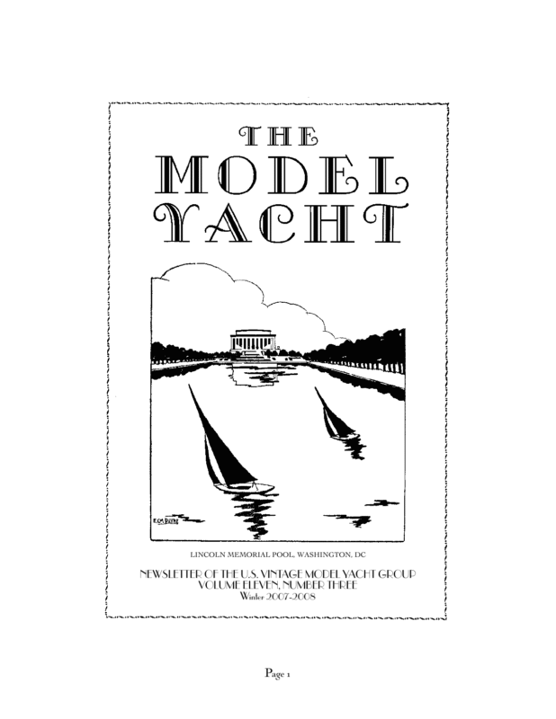
LINCOLN MEMORIAL POOL, WASHINGTON, DC NEWSLETTER OF THE U.S. VINTAGE MODEL YACHT GROUP VOLUME ELEVEN, NUMBER THREE Winter 2007-2008 Page 1
Editor’s Welcome nd so we finish our 11th year of publication. Time definitely goes quickly when you are having fun! It was a busy year for us for both free sailing and radio events, much travel and enjoyable visits with old friends. The biggest news for us personally was the inclusion of reprinted articles from this newsletter in the AMYA quarterly, and the availabilty of Yankee III hulls from Heron Composites: www.freewebs.com/heroncomposites In this issue we present what has to be the simplest vintage sailing craft possible, and one which was designed by the renowned naval architect William Atkin. After many years we have a new update to the Vintage Marblehead rules and we include an important historical reprint from 1921 describing skiff sailing in Prospect Park. And again we are lucky to have our pages graced by the always entertaining Windling World column by Mark Steele. We also document the early evolution of the Marblehead Class by printing two designs from the the same designer, but one year apart: James A. Potter’s Wampum and Wampum II. Finally, since this Season is really for the children, we reproduce what we treasure as the most delightful of our collection of old pictures of young people and little boats. Best wishes to all our readers for a healthy and happy 2008. Ebbs and Flows The President’s Message Vintage Membership reminder that starting with renewals of the next issue, VMYG annual membership will become $25 for three issues of our newsletter The Model Yacht. It will be $30 for members outside the U.S.and Canada. The VMYG lifetime membership will increase to $125. Members also have access to technical assistance and vintage model plans, and details on VMYG-sponsored events. To subscribe to or renew your newsletter and services, send check (payable to US VMYG) or cash to: John Snow, c/o US VMYG, 78 East Orchard Street, Marblehead, MA 01945. For more information, you can call John in Marblehead @781-631-4203 or visit the VMYG Web Page www.usvmyg.org 2008 Vintage M (VM) National Championship Regatta The 2008 national event for R/C VM 50-800 and Vintage 36 (V36) models will be at Spring Lake, NJ September 12 – 14. It will be hosted by The Marbleheaders of Spring Lake, NJ MYC. Contact VM Coordinator John Henson in Brick, NJ for emerging details at senlivjh@aol.com or 732-458-1370. Earl Boebert Page 2
2008 Traditional Sailing Craft/Scale Model Regatta Details are still to be defined for this 2008 VMYG-sponsored event. Thus, contact our Traditional Sailing Craft Coordinator Joe M. Cieri at 732-244-1047 or 10 Abaco Street, Toms River, NJ 08757 for more insights. Joe’s priority is a NJ-area regatta sometime next Spring for these traditional sailing craft, which include schooners and skip jacks. Other Related 2008 Vintage Activities May 11: Free Sail Vintage 36 Restricted Class Invitational Regatta for vane and Braine gearsteered 36R models hosted by the San Diego MYC. June 7: R/C VM Full Cup Invitational Regatta hosted by the Marblehead MYC. June 27-29: 2008 WoodenBoat Show at Mystic Seaport Museum, CT. VMYG and AMYA may again share exhibit tent and stage daily R/C sailing demonstrations. July 12: R/C VM Invitational Regatta hosted by the Laconia MYC in NH. August 21-24: Model Yacht Regatta renewal at Mystic Seaport Museum, CT for classic AMYA designs: J Boat, EC-12 Meter, Star 45, etc. co-hosted by AMYA and VMYG. October 18: R/C VM Bithell Cup Invitational Regatta hosted by Marblehead MYC. Marblehead 50-800 Class History Article AMYA Model Yachting magazine Issue #151 will have feature article (25 pages) that chronicles the 75-year history of the M 50-800 Class from 1932 to 2007. It is to be distributed to AMYA members in Feb-Mar 2008. This article includes details on the development of M designs and rules from 1929 to present, notable M Class milestone events, building wooden VM models at WoodenBoat School courses with photos, and a comprehensive 2007 VM National Regatta report with photos. Cover for this issue will show the start of a free-sail VM race at Redd’s Pond during 2007 VM event. I want to express my personal thanks to VMYG members Earl Boebert, Thom McLaughlin and Harry Mote, plus Pat Butterworth of AMYA, Stan Goodwin of Marblehead MYC and Ray Davidson of Metro Marine Modelers of Toronto, as key contributors to this article. Classic RM Design Grouping – Stan Goodwin, current AMYA M Class Secretary, will evaluate interest in establishing an R/C M (RM) design category for early AMYA M boats that date from 1971 through 1985. This will be in 2008 via five-race RM series sponsored by the Marblehead MYC. It will include an RM Invitational Regatta June 28 at Redd’s Pond with the historic 1934 Campbell Cup as its perpetual trophy. Readers interested in this RM design concept and these races should contact Stan at sgoodwin@draper.com or at home in Marblehead at 781-631-5847. Contact John Snow at 781-631-4203 or VM 50-800 Model Kit – GRP Model Yachts has a high-quality, fiberglass replica kit of the Gus Lassel 1940s Sun Wind Marblehead design available. Visit the GRP website for more details at jsnow@drc.com for evolving details on these activities. Vintage Etcetera VMYG “How To” Model Books – Visit the VMYG website for details on ordering our “how to” vintage model building books and DVD by our Historian Earl Boebert. These are based on wooden, plank-on-frame method to construct 1940s era model racing class designs (with DVD), plus modern building techniques to derive an R/C model of the 1930 I J Boat design. Yankee III is 36inch, entry-level model, which also qualifies as V36 design for VMYG events. Page 3 www.modelyachting.com or call Adrian Olson at 831-724-7000.
`Of Webfooters, Direction-Changers, Favourite Boats, Not-quite-Footy Footies, and a Purpose-Built Boatyard’ Fall into Victoria Water, sailing venue of the Christchurch New Zealand Model Yacht Club and you automatically gain membership of the Webfoot Club. Here’s some advice though, remember to keep your buttocks tightly clenched to avoid water rushing in and causing severe internal damage. Model shipwright’s workshops, wherein some of those beautiful and detailed sailing ship replicas slowly take shape, are generally full of wood offcuts, shavings littering the workbenches and floors, plans and tools, paints, brushes and varnish, and of course previous models, all testimony to hours of work and enjoyable times spent sailing the completed boats after. These `dens of creation’ vary in size of course, but Derek Nicholson of Auckland, New Zealand when having his current house built, put a lot of effort into the separate building where he would spent most of his remaining years creating the fine sailing models for which he is known. His latest is the Athena, the real boat built for Netscape `kazillionaire’, Jim Clark. Derek Nicholson’s workshop, with the model of Athena in the foreground. Page 4
Roy Lake and his magnificent schooner. Ship modelers and windlers subject interests beautiful ketches, cutters and schooners — sometimes change as they develop new pasinstead he and wife Lois though still sions. Roy Lake of Auckland, now closing in weekend-sailing one metre boats are building on his eightieth year, has built so many a garden model railroad. We have one life lovely model each of us s a i l i n g and some of b o a t s , us wish to maybe over use a part of a thirty year it in pursuit p e r i o d , of other boats that hobbies. included the Someone stunning once wrote schooner `there is a which he is very fine seen with. line beHe now t w e e n produces hobby and u t t e r l y mental illamazing ness !’ . I model cars guess we entirely out dedicated of wood. hobbyists Ken Lockley are all a bit of Canada, mad at choalthough sen times in still sailing a our lives ! one metre One of Ken Lockley’s schooners on a Canadian lake. no longer produces his Page 5
These `senior’ sailors of Sheffield in England, three of a group of five sail Footy boats that are not a foot long. (or they don’t fit into `the box!’) Do you think these gentlemen worry about such a trifling matter, after all they are not serious racing types, instead they enjoy building and having fun with their `footynot-quite-a -footy-sized ‘ boats. Ron Rule’s visible Starlet, called Sea Thru. Old-timers will recognize this design as the first of the 36/600 Class in the U.S. I am sure I have emphasized before, you can cruise or windle with any style of boat, even this clear Perspex entirely see-through Smeed Starlet appropriately called Sea Thru built by New Zealand Ancient Mariner, Ron Rule who incidentally gave up copper sculpture to get into model sailboating. With frames of 5mm Perspex, 2mm Perspex used for the sides, bottom and deck, though heavier than the normal conventional Starlets, this one keeps up adequately with other boats, and if the sheeting is fouling inside the hull you can see exactly where at a glance. To Footy or not to Footy (and there are many who absolutely hate them). Island Spice (top) and Jammon (bottom). Two windlers own windling favourites, my own John Spencer designed una rigged (just one mainsail) Fun Fellow, Island Spice, possibly the only FF sailing anywhere today. An absolute delight to sail, easy to rig it is one metre in length and has a shallow draft 7″ keel and bulb. Absolutely loves flat water and light to medium breezes. Steve Levesque in MA, USA favours his John Storrow design Orca, Jammon, photographed here with Steve by Bill Richards also of that State. The “Footy-ish” windlers of Sheffield. Page 6
How to Make a “Straddle Bug” Editor’s Note On first encounter in an old magazine, one might be tempted to thumb right by this odd and apparently oversimplified sailing craft; tempted, that is, until one read the byline: “William Atkin, N.A.” Atkin was one of the most prolific designers of the first half of the Twentieth Century, designing upwards of twenty boats a year. In addition to this he was an author and at one time editor of Yachting magazine. He was distinctive in his field for never having designed a racing craft, but he designed everything else in sail and power: cruisers, fishermen, day sailers, livaboards, and innovative power boats such as “tunnel hull” designs, so fuel-efficient that Page 7
people are still trying to figure out how they work. The book he produced with his son and design partner John Atkin, The Book of Boats, is a classic in its field. He presented the “Straddle Bug,” essentially a iceboat on floats, in Popular Mechanics in 1925. Despite its simplicity the “Atkin touch” is visible int the tapered spars, the seamanlike method for tightening the shrouds and the pin rack to control the sheets. It is so simple and inexpensive that no one now has an excuse not to own a vintage sailing model. Straddle Bug ew tools are required to make the sailing model described this article, and there is no tedious shaping and carving to be done on a hull. The hull in this model — if it can be called by this name — is nothing but a simple framework to hold the mast and three floats. This construction, while it does not give the model the speed of a ‘regular” body, permits the boat to be knocked together very quickly, and, despite the unconventional design, the little yacht is really a splendid sailer. Before going on with the details of construction, we will explain a few of the terms used the drawings, to save trouble later on. The hull, or body of tile boat, needs no description, nor does the mast. The latter, however, is braced by five lengths of wire; there are two on each side, running from a point near the top of the mast to the sides of the hull, and these are called shrouds. Another runs from the same point on the mast to the end of the bowsprit, and this is called the jib stay. The bowsprit projects from the bow to carry the end of this stay, and to this stay is fastened the jib, or triangular foresail. The sail nearest the after (rear) end of the model is the mainsail, and in this case it is a “jib-headed” sail. The sails are lashed at the bottom to spars called the main boom and jibboom. On the sails, the upper end is the head, the bottom is the foot, the side next the mast on the mainsail is the hoist or luff, and the opposite side, the leach; on the jib, the side that runs on the jib stay is the hoist, and the inner side the leach. The leach of the mainsail is roached, or curved, to make it keep its shape. The angle that the sails are allowed to take to the centerline of the boat is governed by lines attached to the outer end Page 8
of the main boom and the inner end of the jibboom, and these lines are the main and jib sheets. The corner of the foot at which the sheet of the sail is fastened is the clew, and the opposite foot corner is the tack. Now for the construction. The frame requires three pieces of white pine or poplar, ⅜ in thick by 1 ¼ in wide. Two of these are 30 i. long and the third 35 in long. Measure ¼ in from one end of the 35-in and fasten one 30-in piece to it so that the forward edge of the latter comes to the ¼ in mark, and the crosspiece is exactly central ; use two No. 6 brass screws, 3⁄4 in long. Fasten the other crosspiece similarly, so that the distance between the inner edges of the two is 10 ½ in. Mark a point ⅜ in. from the two ends of each crosspiece and in the center, and drill ⅛ in. holes, and 1 ½ in from each end drive in small brass screweyes for the ends of the shrouds. Measure 3 in from the after end of the centerpiece, and glue to the underside a block ⅜ in thick, 1 ¼ in wide and 2 in long, keeping the center of the block on the 3-in. Page 9
mark. Drill a ⅛ in. hole through both centerpiece and block, on the mark. Three floats must now be made. Make these of white pine or poplar, 18 in long, 5 in deep and ⅞ in thick. On two of them, cut one end as shown in the drawing. so that the bottoms are 15 in long, round off the beveled ends , and, from a point about 7 in. from the after end, taper the floats so that they are about ⅛ in thick at the after edges, then round these. Drill 1⁄16 holes in the positions marked, and then fasten these to the ends of the crosspieces with No. 6 brass screws, 1 ½ in long. The third, or rudder float, is exactly the similar to the others, except only one 1⁄16 in hole is drilled in it, exactly in the center, and but one screw is used to fasten it to the centerpiece, under the little block. Now drill two rows of 1⁄16 in holes along the edges of the centerpiece (Fig. 6) spacing them ½ in apart, for the pins on the end of the sheets, and cut out the mast step or hole. This hole is oblong in shape, ¼ in wide and ½ in long, and should not be finished until the mast is ready to be “stepped.” (See Fig. 4). All of the spars are also made of pine or poplar, and, when tapering these as shown in the drawings, the best way to go about the job is this: Taking the mast as an example, cut it a trifle longer than necessary, and about ¾ in. square. Still keeping it square, plane it down until it is 9⁄16 in square at one end and ¼ in square at the other, the taper being straight. Now plane off the edges carefully until an octagon is produced, and plane off the edges of this in tile same way. The mast can now be finished round with coarse and fi n e sandpaper without difficulty, cut to length, the top rounded, and the oblong step cut on the foot. Notice that the main boom and the jibboom taper from the center to the ends, and that the bowsprit tapers and is round only for 15 ¼ in of its length. The inner end tapers a little, but is kept square to make it easy to fasten it to the “deck.” Measure 38 in. from the deck shoulder of the mast and at this point drive in small brass screw eyes to take the ends of the shrouds ( Fig. 4) . A piece of copper or brass wire is twisted around the lower part of the mast , 1½ in . from the shoulder, and formed into an eye on the after side to take a brass hook on the end of the main boom. This is shown clearly in Fig. 4. Now step the mast so that it “rakes” or leans aft 9 in from the vertical, measured from the top, and glue into place. The shrouds, which are of 20 gauge brass wire, can now be fitted. Each shroud is passed through the screweyes on the mast, twisted as in Fig. 6, and, about 2 in from the deck, is passed through a small brass ring, then twisted around itself and cut off. Now, fasten one end of a length of fine fishing line to each ring, and pass them several times through the deck screweyes and the ring (Fig. 6). By drawing on these lines or lanyards, the shrouds are set up ( tightened) and the mast straightened. The shrouds should not be set up until tile jibstay is in place or the mast Page 10
may be sprung ( bent ). The stay is formed with at loop on the upper end that passes over. the end of the mast and rests on the screweyes; the other end is fastened to a small brass screweye on the end of the bowsprit, as seen in Fig. 1. The sails are made of light-weight percale, and must be cut so that a ⅜ in. hem may be made on all sides. Remember that there is a l in curve (roach) on the leach of the mainsail and a slight roach (about ¼ in.) on tile hoist. The edges of the jib are straight. Twelve small holes are punched through the foot of the sail and 15 on the hoist; if small eyelets like those used on shoes can be put in these, so much the better — maybe the shoemaker will do allis f or you. Seven are also put through the foot of the jib, and about 12 on the hoist. The sails are laced to the booms, stay and mast through these eyelets by means of light fish line, as shown in Figs. 1 and 6. There are two small holes drilled at the head of the to take the end of the lacing and make it fast, and similar holes in the booms. The lacing on the hoist of the jib can be taken to the shroud screweyes and made fast there. The only work left now is the sheets. These are also of strong fish line. One end of the jib sheet is fastened to the after end of the jibboom, reeved through a screweye near the after end of the bowsprit and passed aft; it is then cut off near the end of the row of holes in the centerpiece, and fitted with a pin made of brass wire (see Fig. 6). The main sheet is fastened to the after end of the main boom, and leads down through the screweye in the end of the centerpiece, then forward. The rudder screw should bind the rudder float tightly, but not so tightly that the float cannot be moved with the fingers. Crossing the starting line of a triangular course. Page 11 William Atkin (1925)
Racing Model Yachts Editor’s Note This article, which appeared in Country Life magazine for July 1921, documents the continued tradition of skiff sailing on Prospect Park lake, a tradition that did not end until well after World War II. The large schooners are similar to those depicted in pictures we have from the late 1880s; this was a slow period in model yachting development in the United States; ironically, just as this was published William J. Daniels had issued his challenge for a contest between the United Kingdom and the United States, an act which energized model yachting here and led to the formation of the Model Yacht Racing Association of America as well as the Yachting Monthly Cup. Racing Model Yachts stranger, walking or driving through Prospect Park in Brooklyn, N.Y., on a Saturday afternoon or Sunday morning, might be rather startled on arriving at the large lake, to see numerous yachts scudding about in the breeze, until he observed that the yachts were only small editions the usual boats seen at any big yacht club regatta. On further observation he would notice that each yacht was followed by a rowboat containing one person—usually the owner of the yacht. If the visitor should be fortunate enough to arrive on the banks of the lake when one of the model yacht races is about to start, he would see a very lively scene. Probably a dozen yachts, with their owners in rowboats, will be congregated nearing the starting line, all trying to get a favorable position for crossing. The starting line is formed by placing a buoy out in the lake opposite the place where the official starter of the club has taken his station. As in the large yacht races, the rules are all strictly observed, and each yacht is timed as it crosses. At a signal from the starter, the yachts come rushing across the line, some of them inevitably getting mixed in with the spectators in their boats, who crowd in In front of the Prospect Park Model Yacht Club clubhouse at the start of a race. Page 12
amongst the racers in a tantalizing manner. sails the model yacht has drawn the design, built the model, and fitted it out, even to the making of the sails and rigging. The lucky ones soon glide out on the lake and make great headway toward the first mark, if the race is on a triangular course, and an exciting moment comes if several try to round the buoy at the same time. lf the race is to windward and leeward, the course has to be covered twice, but only once around in the triangular course, as it is fiveeighths of a mile long. The educational value of the model yacht races is not the most important part of the sport, for the physical exercise and the charm of the outdoor life soon tans the skin and builds up the physique of the yachtsmen. The easy positions that the men assume in the rowboat can Lieutenant Tucker shepherds Yankee Girl come only from If the breeze be long practice. very strong yachts will heel over until the During a race, one may be seen slipping up sails almost touch the water, but they always behind his yacht to make the necessary right themselves before going over too far. It changes and adjustments, sometimes even is really astonishing to watch these boats outlying full length on his back in the boat the sailing a breeze so stiff that one would natuoars in the meantime swinging from the rally think it impossible for them to survive. locks. In going to windward the yachts sail much the same as the large boats, only, in changing tack, the owner swings the sheet around; he is penalized five seconds each time he touches the boat. In running before the wind no spinnaker is used, the mainsail being swung to one side. Accidents happen quite frequently, as it is not unusual for some of the outsiders in their rowboats to get on the course of the racing yachts; and many a torn sail and smashed bowsprit have to be attended to when these onlookers are too slow in getting out of the way. It is surprising to see how one yacht will pull away from the others and cross the finishing line with quite a lead over the other contestants. Sometimes a yacht will get its deck or hull sprung, allowing the water to leak inside, thereby cutting down its speed considerably. Collisions very often happen amongst the yachts themselves, but the damage is soon repaired when they get back to the clubhouse. Although the design and build of the model yacht have a great deal to do with winning a race, the seamanship of the owner counts considerably. The training that these men get in the handling their boats — as well as in designing and building them — will be of great value to them in future. In many cases the man who The model yachts, when painted, look spic and span, each owner relying upon his own taste as to the color used. One has his boat painted a dark green, with a gold stripe running around at the water line; others are painted white; but the varnished mahogany Page 13
hull seems to be the most popular. The sails also vary in color, some being white, some yellow, and others tan color. The shape of the sails also varies, some of the yachtsmen preferring club topsails, while others have the mainsail all the way up the mast and in one piece. which prizes are also awarded. The regattas are held on Decoration Day, Independence Day, Labor Day, Columbus Day, and Election Day; and the point races are held on the usual Saturday and Sunday races. The clubhouse of the Prospect Park Model Yacht Club is built of rustic wood and has a landing float connecting with the water. When sailing before the wind, the mainsail is connected with the tiller, with the the rudder set on On entering the the same side as clubhouse one the mainsail. In s e e s a b o ut beating and s e v e n t y fi v e reaching, howmodel yachts of ever, the tiller is various sizes, left loose, allowwith all sails set, ing the rudder to neatly arranged swing free, folin a circle conlowing the line of forming to the the keel. The shape of the tiller swings on a Measuring a model yacht building, and leavhorizontal bar ing space to walk with an adjustable nut at either end, and can behind the yachts all around the floor. The be very quickly placed in the required posicentre of the room is left free for the yachts, tion. and the bulletin board is hung on the pillar in The members of the Prospect Park Model the centre of the room. Yacht Club are very much in earnest in their Each yacht rests on a cradle with wheels, work with the small yachts. Every Saturday thus enabling the owner to transport it very afternoon and Sunday from Decoration Day easily from the clubhouse to the water. The until Election Day they are to be found either yacht is lifted clear of the cradle and placed in the clubhouse tinkering with their yachts, in the water, while the cradle is returned to or out on the lake practicing for their races. the clubhouse, leaving the boat clear for the Every race is accurately recorded and each others. boat’s performance is posted on the bulletin On the float, ranged alongside the clubhouse, board which hangs in the clubhouse. On restands a tank about six feet long and three gatta days a small money prize is awarded; feet high. This is the measuring tank in but points are kept for the season’s work, for which, when filled with water, the yachts are Page 14
Interior of the clubhouse, showing model yachts being groomed for a race. (Note the little boat at the feet of the small boy standing in the background—Ed.) placed for measuring. The official measurer places his rule along the side of the tank, sighting along the ends to get the waterline. Sail area and length over all are also recorded. The official measurer has an assistant during this work.1 At present the Prospect Park Model Yacht Club is composed of the former members of the Brooklyn Model Yacht Club and the Yankee Model Yacht Club. These two clubs decided to join together and form a strong organization; and so far the change has been a success William Henry (1921) RC Vintage Marblehead Rating Rules Update 2007 Background t has been approximately seven years since we reviewed the class rules for the USVMYG Vintage Marblehead. A lot has happened since then. A number of new boats have been built; and we have added a new Vintage Marblehead division, called Transitional, to the two original divisions of Traditional and High Flyer VMs. Glass hulls of Madcap were produced for youth mentoring programs and Scott Todd The yachts were divided into classes by load waterline, and within each class given a time handicap as a function of sail area. This worked because, although all boats raced at once, the races were actually against the clock. —Ed. 1 Page 15
plans to produce glass Madcap hulls from a plug made by Alan Suydam. And there is now a fiberglass Sun-Wind kit available from GRP Model Yachts. Interest in VMs generally seems to be increasing. We thought it time to review and update the Vintage M rules. To achieve this I put together a committee of Pete Peterson, Harry Mote, Alan Suydam and myself, with the goals of accommodating recent class history, clarifying the rules in areas where questions have occurred, anticipating future class growth and maintaining the vintage appearance of the boats and vintage spirit of the class. Vintage Marblehead class divisions now include: Traditional: Existing designs from 1945 and before and new designs with proportions of rig, hull weights and design characteristics of this period. revised by consensus or recommendation by Vintage Marblehead class owners. The rating rules for the Vintage M divisions are based on the Marblehead 50-800 Class rule adopted by the Model Yacht Racing Association of America (predecessor of the American Model Yachting Association) April 14, 1932, corrected to June 1, 1939, and with the inclusion of the Sailing Rules of September 1942. Subsequent editions were “corrected” to accommodate the evolving Marblehead 50-800 development class. Traditional Vintage Marblehead Design Formula A sloop-rigged monohull model sailing yacht with an overall maximum length of 50 inches, plus or minus one quarter of an inch, and a total sail area not to exceed 800 square inches. Prohibited High Flyer: Existing designs from 1946 to 1960 and new designs with proportions of rig, hull weights and design characteristics of this period. • Sliding or adjustable keels • Centerboards • Leeboards Transitional: Existing designs from 1961to 1970 and new designs with proportions of rig, hull weights and design characteristics of this period. • Bilge-boards • Bowsprits • Transom-mounted rudders or rudders that extend aft of the transom • Outriggers, pontoons, or twin hulls • Moveable or shifting ballast • Prognatheous keels: No portion of the keel appendage, including the lead, may project forward of the leading edge of the keel fin • Metal fin keels • Materials with a density greater than lead • Carbon fiber or Kevlar in the hull, rudder or rig • Fabric, film, balsa, foam or fiberglass decks • Mylar or other modern plastic-like materials in sails • Swing rigs As designs of the Marblehead evolved in its development during these early years, the boats became heavier, deeper, taller and faster. The reason for divisional breakdown by time period is to group boats not too dissimilar in performance to create somewhat equitable competition on the race course. Participants in Vintage Marblehead classes are generally motivated as much by the pleasures of the beauty, construction and sailing of these early designs as they are by onthe-water competition. Consequently, appearance as well as performance are factors in these rules. Compliance with the rules in these divisions essentially relies on an honor system by gentlemanly builder/sailors. It is the responsibility of the owner/sailor to prove compliance with the rules when challenges occur. These revised Vintage Marblehead Rating Rules of 2007 shall govern Vintage Marblehead activities from date of publication until Page 16
Hull Rig Hulls shall be constructed by the methods and of the materials of the period as follows: Bermuda, Marconi, jib-headed mainsail, gaff, gunter, wishbone and other types may be used. 1. Hulls shall be constructed primarily of wood, using plank on frame, cold molded, or horizontal and vertical lifts. It is permissible to cover a wood hull with a light layer of fiberglass cloth to add strength and prevent leakage. Balsa strip planking covered with fiberglass, in which fiberglass is the primary strength of the hull, is not permitted. 2. Fiberglass hulls laid up in a mold are permitted. Minimum weight of fiberglass hulls is two (2) pounds. 3. Garboards shall be hollow, with not less than a one inch radius in the area of the keel fin. This may be checked by use of a disk 2 inches in diameter, fitted to the garboard at a midship section. 4. Modern adhesives are permitted to produce a strong hull impervious to leaks. 5. Draft shall not exceed 12 inches on a model yacht fully rigged and ready to sail. Minimum keel fin chord length shall be five inches. 6. All ballast must be fixed and shall not be changed during a race or series of races. 7. Model total weight shall be in keeping with that of the period. 8. Bumpers are mandatory and are limited to one half inch overhang. Bumpers are not included in the overall hull measurement. 9. Rudders shall be keel- or skeg-mounted in keeping with the design characteristics of the period. It is permitted to enlarge the area of the rudder from its original size to achieve acceptable steering with radio control. The skeg must be at least 50% of the rudder in area when the rudder is skeg-mounted. Balanced or spade rudders are not allowed. Changing rudders during a race or series of races, except in bona fide cases of damage, is prohibited. 1. Alternate rigs are permitted provided the sail area does not exceed 800 square inches. Details of such rigs must be comparable to the original sail plan. 2. Spars shall be constructed of the materials of the period, primarily wood.Round aluminum tubing is permitted. Modern extruded aluminum spars, designed and produced for modern model sailboats, are not permitted. 3. Maximum diameter of spars is ¾ of an inch. 4. Maximum height of the head of the mainsail above the deck (see sail measurement) is 85 inches. 5. Height of the jib head stay above the deck shall not exceed 80 percent of the height of the head of the mainsail above the deck. 6. Hollow masts and spars, permanently bent masts and spars, and rotating and bipod masts are allowed. Fittings Fittings for deck and rig should be made of brass or other metal in keeping with materials and practices of the period. Sails Sails shall be constructed by the methods of the period. 1. Sails may be constructed as either a single or multi-panel sail. 2. The body of each sail shall be made of woven cloth, such as cotton, a cottonsynthetic blend, Dacron or Nylon, such as light spinnaker cloth. No material other than woven sail cloth is allowed for tablings or corner reinforcements in the head, tack or clew of any sail except sail reinforcing tape. Deck 3. Mylar or other modern plastic-like materials are not allowed. 1. Decks shall be constructed of wood: solid, planked or plywood. Film, cloth, foam, balsa or fiberglass decks are not allowed. 4. Roach of sails shall not exceed two inches. Rounded foot of loose-footed sails shall not exceed one inch. Page 17
5. The roach and the rounded foot of sails shall be a continuous, arc-like curve from head to clew and from clew to tack. 6. Mainsail battens shall not exceed four in number and four inches in length and they shall divide the mainsail leach into approximately equal parts. Headsail battens shall not exceed three in number and two inches in length and they shall divide the headsail leach into approximately equal parts. from a point at the head of the sail where its width is ¾ of an inch. The diagonal is measured from the aft edge of the clew to the closest point on the luff. The sail area of each sail is given by:Sail Area = luff measurement x diagonal measurement /2. The sum of the areas for the jib and mainsail must be less than 800 square inches. 7. Headsticks or headboards shall not exceed ¾ of an inch across the base for headsails and mainsails. No other wire or stiffener shall be put in the head of the sails Sail Measurement 1. Rig and mainsail measurements are taken from the underside of the ¾-inch base of the mainsail headboard. Thus, the height of the mainsail above the deck measurement and the area of the mainsail are taken from this point. All Vintage Marblehead Yachts shall be officially registered with the VM class Coordinator to obtain an official sail number. Sail numbers shall be preferably black, three inches tall, ½ inch in thickness and they shall be affixed to both sides of the mainsail between the second and third battens on a line perpendicular to the leach. The VM insignia consists of a red “V” nested in the top of a black “M” as shown above. The letters are 1 ½ inches tall, 1 ¼ inches wide and ¼ inch thick. The “V” is separated from the “M” by 1/16th inch. The insignia should be placed in the upper quadrant of the mainsail and only on the starboard side. 2. Calculation of sail area: Lu ff Luff Radio Control Dia g Only the rudder, headsail sheet and mainsail sheet may be adjusted by radio control. Diag High Flyer Vintage Marblehead The measurement of sails is specified in the 1958 MYRAA Handbook. Only the actual sail area, excluding roaches and the rounded foot of loose-footed sails is measured. The above drawing indicates the layout for triangular sails. The luff is measured from the lowest point on the tack of the sail to the bottom edge of the stick or headboard. If the sail has no headboard, the measurement is taken The rules for the High Flyer division are the same as those for the Traditional division except for the following: 1. High Flyer Marblehead hull design, rig, sails and keel configurations must follow those of the period. 2. Rudders may be of the spade or balanced type; that is, independently suspended Page 18
and not attached to the keel or a skeg. Marbleheads of any design of the Traditional period that use a spade rudder shall be classed with the High Flyer division. use of “rules of thumb” of the period to reconstruct the rig is of particular interest. Munro’s Notes ur design this month is for a little Schooner that was built about the year 1825, for trading on both sides of the Scottish coast, and able to pass through the Forth and Clyde Canal. 3. Draft of a High Flyer model yacht fully rigged and ready to sail shall not exceed 16 inches. Transitional Vintage Marblehead The rules for the Transitional Marblehead division are the same as those for the High Flyer division except for the following: 1. Transitional Marblehead hull design, rig, sails and keel configuration must follow those of the period. 2. Draft of the Transitional Marblehead model yacht fully rigged and ready to sail is to be determined. Comments and questions on Vintage Marblehead Rating Rules and boat registration should be addressed to John Henson, Vintage Marblehead Coordinator, 1212 Sandra Place, Brick, NJ 08724, 732-458-1370, senlivjh@aol.com. John Henson Schooner of 104 Tons Editor’s Note There has been a resurgence of interest in scale sail, if the chatter on the Internet is any indication. The most glamorous boats of course, tend to be picked as prototypes: clipper ships, racing schooners, and so forth. But the humble working boat has its own charm, as shown by the little schooner opposite. Because the act of scaling down a sailing craft destroys the original relationships between sail area and righting moment, one looks for prototypes that were somewhat undercanvassed for their size, and this schooner meets that criteria as well. She should make a fine sailing model, requiring minimum external ballast, and would even be a good subject for a scale “Footy.” She was documented in a series of articles by G.W. Munro in Marine Models for 1937. Munro specialized in historical vessels for that magazine, and what follows are excerpts from his descriptions. His 1 The main dimensions are as follows: Length of Keel, 54ft. 3in.; Length for Tonnage, 63ft. 2in.; Breadth of Frame, 19ft.; Breadth for Tonnage, 19ft. 6in.; Depth of Hold from Deck to Ceiling, loft. 8in. It will be noticed that she has her midship section rather far forward from the usual, and that her bows have a sharpness which is also unusual for this period. Altogether, the design is a very advanced one, but we must remember that most of the experimenting was taking place at that time on the NorthEast Coast of Scotland, and that it was from there that not a little of the advance in sailing merchantmen design took shape. The frame spaces are 2ft. apart, and in the design every second frame is shown in the middle body. There is one cant frame shown at the stern, and this is shown in conjunction with the transoms. The deck plan ls very typical of the average merchant vessel of this period, and needs very little explanation to make every point clear, even to the beginner in ship model making. The first point which will be noticed is the rational way in which the builder has strengthened up the beams with carlings 1 just where the stresses will come the most. It should be pointed out that the length of the beams is only shown between the bulwark rails, and not their actual lengths. This is owing to the amount of tumble-home in the topsides. Or “carlines,” which run fore and aft between the transverse beams.—Ed. Page 19
Schooner of 104 Tons (1825) Page 20
The deck breasthook can be seen fitted to the foremost deck beam. This breasthook is so placed to take the ends of the deck planks at the fore end. The shape of the breasthook —and the rake of the stem—is maintained by the small carling at the centreline and this in turn is backed up by a pair of bitts on either side of the bowsprit. The windlass is of normal pattern. If we make the thickness of the windlass bitts one-third of the diameter of the windlass, they will be in good proportion. The cat-heads on either side of the bows should be sized one-third of the extreme breadth, taking inches for feet. The depth should be 1/7th or 1/6th more than the sided dimension. No indication of the position of the capstan is given on the original plan. This also applies to several of the other deck details. We can only presume that these little points were settled by the captain after the vessel was launched and being fitted out. Naval architects used to—and still have—a nasty knack of showing strings in most awkward positions, and many owners allow the captain to arrange these matters during the building of the vessel. In the deck plan it will be seen that the Schooner has one large main hatch and three smaller ones aft. These latter are arranged as skylights and companionways. I should imagine that the one just aft of the mainmast is the companionway to the saloon. The one aft of that is a skylight, and the aftermost one a small hatchway to the sail locker. It should also be noticed that the pumps are shown just abaft the mainmast. The mast carlings are arranged to make a tight fit on either side of the mast and abaft it, and then cut away to allow the necessary play everywhere.. Page 21
I have not got the original sail plan, as she was actually rigged, but I have endeavoured to set out this sail plan according to the original designer’s ideas and methods of proportioning the sails and spars. It will be noticed that the foremast head is rather long when compared with that of the mainmast. The reason for this is that it might be desirable to fit yards and make a Topsail Schooner of the vessel. On the other hand, the modeller can make the foremast head equal in length to that of the mainmast. In doing this the actual length of the mast must not be changed, but merely the proportion of the head to the total length. A few quotations from the original author’s remarks will be of some interest to the reader: Schooner-rigged vessels have two masts, but these are of a very deferent proportion from those of a Brig, the masts of a Schooner being nearly as long as those for a Sloop or Smack-rigged vessel of the same tonnage. The principal design of the two masts in the Schooner is to divide the sails into smaller portions, particularly the mainsail. The Schooner’s mainsail is set with a boom and gaff; they have two foresails, called the boom and stay foresail. The boom foresail is set with a boom and gaff, or sometimes with a gaff only, and sheets. The stay foresail is made to run up upon the forestay, which is fixed either to the stem-head, or a short way out on the bowsprit, with a jib without the foresail; also, a square sail with yards, ropes, etc. These used formerly to be the principal sails of a Schooner, and the advantages of the rig are, that by it the vessel sails close to the wind, the sails are easier managed and worked in narrow channels, and with much less wear and tear than Smacks and Sloops. The rig of Schooners has, however, been considerably altered within these late years. In addition to the above, they now have a gaff-topsail aft, square topsail and topgallant sail on the foremast, jib-boom, flying jibboom, square sail, studding sails, etc. To find the length of the mainmast for a Schooner: To three times her extreme breadth, add one-third length of the L.W.L., and the depth of the hold from the upper part of the keel to the deck, and two-thirds of the sum is the length of the mast. Or, to find the length above deck: Multiply the momentum (i.e., the sum of one-third the L.W.L. by three times the breadth and the depth) by .55, and the product is the length above deck. The foremast is generally from 17-18ths to 1920ths of the length of the mainmast. The length of the mast heads, from the lower part of the trestleetrees to the top, is 2-13ths of the full length of the mast for the mainmast. The foremast head is 1-5th of the same. The diameter of the mainmast is tin. for every 4ft. of full length. The diameter of the foremast is 1 in for every 3 ½ ft of hull length. The length of each topmast is one-half the length of the foremast. The length of the poles is about 16th of the topmasts. The diameter of the topmasts at the cap is 1 in for every 4 ft of length. The main-boom is arranged to have one-third its length abaft the sheet. The gaff is two-thirds the length of the boom. G. W. Munro (1937) Festive Editor’s Note William J. Daniels was one of the premier, if not the premier, designer and builder of model yachts in England in the first half of the Twentieth Century. He designed relatively few Marblehead class boats, concentrating instead on the 10-Rater and A Classes. This design, published in Model Maker to coincide with the 1951 Festival of Britain, has a typically balanced Daniels canoe body; his conservatism is most manifest in the sail plan, with its low 58 in hoist—this at a time when boats like Rip Tide, designed two years earlier, were carrying sails a foot higher. Materials were hard to come by in England at that time, and Daniels designed this boat to allow for overbuilding on the part of novices. With a design displacement of 20 lbs it would be a very heavy boat for American conditions. The plans as originally published are distorted and are included here primarily for illustration; if you choose to build one, you should not rely on a simple enlargement but re-fair the lines. This can be done on the building board by springing battens along the shadows and sanding off the high spots. It is far more important that the lines be fair than that they match some old drawing. The text of the article describes the traditional plank on bent frame construction that we have covered several times before, so we are presenting just the comprehensive photographic accompaniment which will give you a good idea of what one of these boats looks like in the course of construction. Page 22
(Upper) Cross-section of shadow, showing rib recessed into keel with overlapping planks. (Lower) Center shadow, showing cheek piece added to keel. Page 23
(Above.) The shadows attached to the T-section wooden strongback. This must be straight and flat; another way to make one is to bolt two sections of aluminum angle together. The front shadows are placed with their back surface at the section line and the aft shadows with their front surfaces there. The shadows are sanded to fit the contour of the hull, with fairness checked by springing battens at various angles. (Left). Detail of the shadows. They are made in two pieces so they can be removed easily, and joined by screwing them to the crosspieces. This picture also shows the notches for the inwales and the keel. When building a hull in this fashion it is only necessary to have accurate drawings of the sections and a rough approximation of the profile; all other shapes are derived by the process of fairing the hull. (Right) The transom piece, cut to its true shape and screwed to a dummy shadow. Some builders cut the transom and the shadow as one piece, cutting it down to shape after removing the hull from the strongback. Using a dummy, as shown here, permits a more accurate shaping of the transom. Page 24
(Left) A bent frame attached to its shadow with brads. The small squares of cardboard under the brads are there to facilitate pulling the brad out when the planking gets close. The strip of paper is there to prevent the glue used in planking from gluing the rib to the shadow. Ribs are generally made from oak, which must be soaked or steamed to enable it to be bent without splitting. Note how the rib overlaps the inwale. Some builders leave a gap here, others glue in filler pieces to make a stronger joint where the hull comes together with the deck. (Below) The hull ready to plank. The ribs are in place and the keel has had the cheek pieces added where the fin will be attached. (Above) The partially planked hull. This hull is planked from garboard to sheer. Some builders plank in the other direction, which makes a nicer look at the sheer line but requires an oddshaped “shutter” plank at the garboard. The planks are tacked in place with cardboardshimmed brads. This is traditional UK practice. American practice is to drill small diameter holes and drive in treenails, or “trunnels” made from toothpicks, which are broken off on the inside when the shadows are removed. Another technique is to tack the planks in place with CA glue prior to applying a covering of light fiberglass cloth and epoxy resin. Page 25
The finished hull from the inside, with the deck beams installed. This design has the mast stepped through a hole in the deck to the keel. If the mast were stepped on to the deck, vertical posts would have to be installed to take the compressive force of the tightened shrouds. What a Difference a Year Makes verleaf we present two boats by the same designer, done just a year apart. James A. Potter was a wellknown designer in the MYRAA days and immediately turned his hand to Marbleheads, producing Wampum in 1932 and more publicized Wampum II in 1933. The contrast between the two boats illustrates the rapid evolution of the Marblehead class in its earlier years. Wampum, like the 1932 Champion Cypher, owes much to the earlier Marblehead 450 class with its light displacement and long fin. A year later Potter has deepened the canoe body and increased the beam and the displacement. The result is a boat of the general form that lasted until around 1939, exemplified by designs such as Madcap, Cheerio, and Helen J. After that the West Coast designers such as Lassel and Houk came up with the “modern” form with its plumb stem and stern and full length waterline. Either of these boats could be made into a fine Traditional Vintage M using the planking technique illustrated in the previous article. No sail plan was published with the Wampum plans, but the one for Wampum II will do nicely. The Wampum plans, dated November 1932, appeared in Model Yachting for March 1933 and the Wampum II in Marine Models for January 1934. The table at right shows the dimensional differences between the two boats. Page 26
Wampum (1932) Wampum II (1933) Archivist: Jim Dolan Measurement Wampum Wampum II LWL 36 37 Beam 8⅞ 9¾ Draft 8½ 8½ Displ. 14 lbs 17.38 lbs Earl Boebert The Model Yacht is published three times a year by the U.S. Vintage Model Yacht Group. Copyright 1998 to 2007 U.S.V.M.Y.G. Reproduction for noncommercial purposes permitted; all other rights reserved. Other copyrights are maintained by the original holders and such material is used here under the fair use provisions of the relevant copyright acts for nonprofit research and educational purposes. Editorial Address: 9219 Flushing Meadows NE Albuquerque NM 87111 Email: boebert@swcp.com Phone: 505 823 1046 Officers of the U.S. Vintage Model Yacht Group: President: John Snow Eastern Vice-President: Ben Martin Western Vice-President: Dominic Meo, III Midwest Vice-President: Tom Pratt Southeastern Vice-President: Thom Mclaughlin Vintage M Class Coordinator: John Henson Vintage 36 Inch Coordinator: Al Suydam A Class Coordinator: Rod Carr U.K. Coordinator: Graham Reeves Canadian Representative: Doug McMain Historian: Earl Boebert Page 27
Sail Plan for Wampum II Page 28
“The Trial Trip” (Artist Unknown) 1889 Page 29


