- THE CURVATURE AND SHEETING OF SAILS FOR WINDWARD airflow patterns

oe. O Ships . Cars – Engineering – Yachts
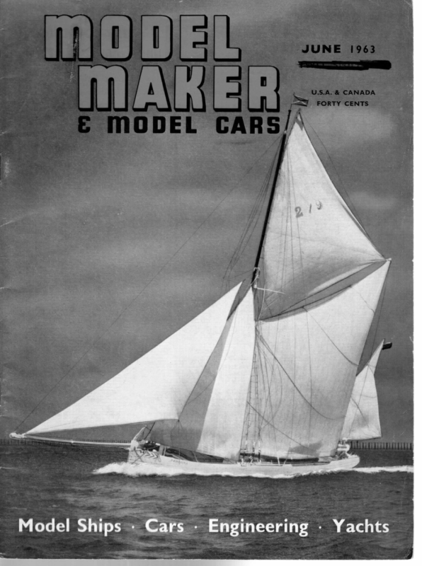
JUNE 1963 Sail Airflow PART TWO Experiments and conclusions drawn Described by Lt. Col. C. E. Bowden, A.I.MECH.E., C.R.AE.S. Photograph on right is Fig. 5 Sheeting and forces involved Every sail placed at an angle of attack to the wind, or apparent wind due to the boat’s forward travel in windward sailing, has a side force component and a forward force component. In sheeting sails, and in their shape, the aim is to reduce side force and increase forward force as much as possible. This is because side force creates heeling, thereby increasing hull resistance when the heeling becomes over 20 degrees. Moreover, the sail’s drive is lower as the heel increases, and the greater the side force becomes, the greater the leeway made. This falling away to leeward creates poor windward performance. We have seen, in Part I of this article, how a relatively flat cut jib, sheeted as parallel as practicable to the mainsail, with the main’s maximum “flow” positioned just ahead of the mid-chord, creates the best airflow pattern and forward drive. Also we saw how side force can be reduced in a strong breeze, by “flattening” the mainsail through hauling down to a wide track, whilst sheeting it well outside the quarter of a keel boat. Let us now examine foresail action by observing wool tufted sails when sailing to windward. The foresail acts as a smoothing slot for the mainsail __ Argument has raged in the past as to whether the jib does in fact act as a smoothing slot. Full-scale and model wool tufted tests made with my boats when sailing to windward close hauled, during the past two years, have proved that a properly cut and jib has an equally broken down flow in lee to a soft sail, when a jib is added the fully battened mainsail provides a big improvement. There is a better flow further up the slot gap. The flow be- hind the soft jib is vastly improved, and the windward side is also very good. The reason is that the stiffened surface creates a better flow through the gap, the curvature is more consistent, and the maximum “flow” can be positioned where it is meant to go. It is signifiacant that this visual improvement of flow is also supported by measurements made last season on my full-scale “X” One Design keel boat whilst sailing to windward in different wind speeds with a fully battened sail and The resulting “curves” of the effective soft jib. drive indicated that a normal mainsail had “A When we poor performance for any airfoil”. measured the full-battened mainsail, with the same jib, the rig’s curve was found to have, “The ideal average gradient with thrust proportional to the square of wind speed”. Battened sails can sail at finer angles without the luff fluttering, and they do not flog with heavy drag in high winds when spilling air. It is not surprising that more and more of the new full-scale boats and Classes are fitting fullybattened sails. What surprises me is, that except for France and a Class in America, very few model yachtsmen and no model Classes that I am aware of, use the fully battened sail. This may be partly due to lack of new classes in the model world. Measurements of wind angles and other factors where the slot exists. True wind speed, apparent wind speed, and angle to the apparent wind, together with speed through the water, are measured electrically in our tests. Minimum friction tensiometers are used in lee of the mainsail is smoothed out, but it is breaking down where the gap narrows at the head of the jib. The flow is completely broken down at the head of the mainsail where there is no slot gap. such tests it has been found that: The full-scale “X” Boat sails to windward in racing conditions, at 26 to 28 degrees to the apparent wind, the six ton cruiser at 30 degrees, and although I have not personally measured this, it is reported in research quarters that a 12 Metre sails at around 22 degrees. We find that free sailing models progress at slightly sheeted jib does have a slot effect creating the desirable “attached” flow on the lee side of sails The large 7 ft. 6 in. long, glass fibre model seen sailing to windward in Fig. 5, with wool tufted sails and a jib sheeted to create a slot effect, indicates that behind the slot gap the airflow pattern in The fully battened sail Wool tufted tests were also made battened model and full-scale sails. on_ fully- Both showed, that whereas a single fully battened sail with no towing and other tests on the sail test-bed, etc. From coarser angles as a general rule. The “X” Boat produced only slightly over 4 to 4 1b. effective drive to windward per sq. ft. of sail area, in winds from 10 to 18 m.p.h. This modest drive emphasises how relatively small increases in 277
WOW MIANRIE:R) THE CURVATURE AND SHEETING OF SAILS FOR WINDWARD SAILING cA) BEST AIRFLOW SHOWN WHEN MAXIMUM CURVATURE SITUATED AT NEARLY 42 CHORD. ; (RELATIVE Y/ “FLAT JIB! , IF MAX: CURVATURE SITUATED WELL FORWARD IN %ROD POSITION, DISTURBED ’ N ‘ AFT OF MAST. ‘ A WELL CURVED re) FLOW JIB UPSETS LEE SIDE FLOW, IF SHEETED SUFFICIENTLY CLOSE FOR CLOSE POINTING IN SAILING. —~—=> WINDWARD found that the airdrag of my full-scale “X” Boat under bare spars, moored to a tensiometer, in no tide, amounted to 6 lb. 4 oz. in the very modest wind of only 8 m.p.h. Also, when towing large models in open seawater, measuring their respective resistances at different speeds, it was most marked how resistance through air drag increased when towing into wind. The suppression of air drag through smoother airflow patterns around sails, cantilever masts, double luff sails, and streamlined decks could all mount up to race winning improvement in windward performance, particularly in stronger winds. In a strong breeze, when racing is really fun, every wire and its interference junction, every sharp deck edge, etc., every conventional mast’s interference, conspire seriously to arrest a boat’s passage towards the wind. Why then do we not redesign these features on our models in a new class or two? At a recent Seminar at Southampton University on yacht research, a well known light alloy mast maker stated that in his view it would be possible to make even a vast 12 Meter full-scale mast fully cantilever with no bracing wires or rods, both lighter and stronger and with far lower drag, provided a certain amount of flexing could be tolerated. Considering that birds rely upon shock absorbing flexing wings tor efficiency when soaring in gusty weather, and that it has been found that a single cantilever Finn mast (full-scale) has actually improved windward sailing when pared down to gain greater flexing in gusts, and better bending back to flatten the sail on the wind, it is only logical that a relatively much smaller model yacht should throw away all bracing wires with their inbuilt headwind for ever! © FLATTISH I make my cantilever model rigs with either laminated spruce masts protected by metal deck sleeves, or from large diameter glassfibre fishing rod blanks. I can then pop the rigs in and out of a deck bearing, and sail with no wires, no bother, and no wasted rigging or dismantling time. JIB — The leng overlap genoa, and its airflow pattern SHEETED CLOSE FLAT CUT Jlé ” har 5a STRONG MAINSAIL DOWN TOO Lo sy MAINSAIL HARD. \ FIG. 7 Opposite top, most powerful sail in its own right, improves the mainsail‘s flow in lee further up the slot gap, and vastly improves its own lee side flow. The mainsail head has the usual broken down flow in lee where there is no slot effect at its head. A jib headed rig for model yachts, with fair flow behind the full height of the mast slot gap has many merits. Even the mighty full-scale 12 Metre yacht’s sails show a close similarity in airflow pattern to the scaled down model seen in Fig. 6. Last season I sailed in a noted 12 Metre yacht during a race for the Queen’s Cup in the Poole Bay Twelve Metre Meeting, which this particular boat won. After the race, a spare genoa, fully tufted as on my 1/9th scale model, was hoisted, and we sailed out once more towards the Needles in a good breeze to observe the airflow pattern on the vast headsail. One might have been looking at the model seen in Fig. 6. One of the difficulties of a “Twelve” is, that owing to its great length, the helmsman is remote SHEETED oe WELL OUT HAULED DOWN VERY HARD \ Fig. 6, bottom, seen that the long overlapping genoa, which is the WIND SHEETED IN, ~~ NOT PULLED A 1/9th scale radio controlled model 12 Metre is seen sailing to windward in Fig. 6 with its standard type genoa, as used in full-scale Americas Cup and other races. Compare with Fig. 5 and it will be SHEETED WELL Our. <> LIGHT BREEZE AND FLATTENED \ ; ! | Fig. 8. | t efficiency through sheeting or improved sail curvature and reduction of drag can pay big dividends in windward sailing. Models are equally affected, particularly as their relative heeling is greater as the wind rises. The evils of excessive drag Drag increases as the square of the wind’s velocity. Therefore, for example, if the air drag of a large boat were 50 lb. in a 10 knot breeze, it would be held back by 200 Ib. in a 20 knot blow. It was from an intimate view of his genoa’s luff to follow the wind accurately. A crew member, therefore, often lies in the bows with goggles to protect his 278
JOINT Ee 3 eyes from green seas and sheets of spray in robust weather, signalling back the exact lifting, etc. of the genoa’s luff. We decided that some strategically placed tufting would assist matters. I have found that wool tufted sails assist in sailing a radio controlled model to windward, for one can see when the flow lifts. The amount of jib overlap The non-overlap jib, as used on a normal model yacht, shows in my tests no appreciable difference in wool tufted airflow to that of a short overlapping jib. This is born out in full-scale practice by the famous Star Class, and also in that during 1930 the Bembridge Redwing keel boat Class, with their interesting and unique freedom to use any type of sail plan with an overall area of 200 sq. ft., found that the fastest all round rig was a Bermudian sloop with jib far enough forward not to overlap the mainsail. Lord Brabazon, a well known experimenter in this Class, who even tried a rotating autogiro rig, found in his small windtunnel that one big triangular sail with clean luff had the best drive to windward, but he was unable to use the rig, because in those days it appeared impossible to go about sufficiently quickly, passing such a sail around a conventional mast and rigging. Today the problem is relatively simple, and my fully rotating and folding cantilever “Delta” rig (now patented) has in many ways solved the one big low triangular sail problem. This rotating rig is also “balanced” on all points of sailing. on its stand, turn it towards the wind so that the sails just fill as in close windward sailing, and take measurements. Curvatures will be found to vary considerably in off the wind sailing. Full-scale Terylene sails, often claimed to be virtually unstretchable, do in fact show considerable How to find and use the curvature of sails Fig. 7 gives the basic principles of sail sheeting and curvature, which can naturally be altered to suit an individual’s taste! Last season I found that I could measure my model and full-scale sails’ curvature and flow position by attaching strings every two feet up each sail, and taking off the curvatures like a series of “sections” or “ribs”. Each string was carried from the luff across the sail parallel to the boom, with a little piece of model aeroplane elastic inserted at the leach end to keep the string taut when sailing. Strings were marked with black dots every 12 in. deformation to another curvature after half a season’s hard racing, when a falling off in performance is noted. This is probably due to loss of “dressing” through “wear”. Triangular sails un[Concluded on page 276] along their length. Model sails had strings every 10 in. up their height, and were marked every 4 in. along their length. The helmsman sails the boat to windward, having wind speed and angle checked by instruments. The “crew” measures the distance from every black dot mark along each string, to the sail’s curvature, and notes it in a notebook. To do this there is a right angle “ruler” marked in % inches to be read from below. The ruler is mounted on a long light bamboo rod to reach the head of the sails from the deck. It is then a simple matter to draw out the “sections” on to a roll of transparent tracing paper. One sail’s curvatures can be laid over another sail for comparison, and to note relative racing results against each other. A winning sail can be remeasured when its performance obviously fades, and the cause will probably be seen in the change of shape that will be found. A model sail in our case is placed on the sail test-bed, seen in Fig. 8, for force measurement and curvature plotting, but most model yachtsmen will not have this appliance. It is, however, reasonably accurate in such cases to put a fully rigged model 279


