- In the Tideway
- MAD HATTER Third of Roger Stollery’s unusual and outstanding Marbleheads. Only 16 lbs!
- TABITHA CAT Fitting the new catamaran class and needing no full-size plans, this simple model by C. Jackson offers a quick introduction to a new form of sailing.

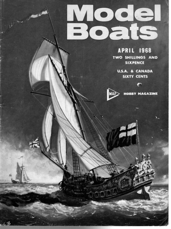
a | ’ | APRIL 1968 — TWO SHILLINGS AND : SIXPENCE | U.S.A. & CANADA | SIXTY CENTS HOBBY MAGAZINE ‘ :
APRIL 1963 In the Tideway mind that any facilities that can be arranged should be available for these individual modellers also and not solely for organised meetings and regattas. The Committee will be very glad to hear from anyone — either individual modellers or clubs who feel that they can give or might require assistance or information in connection with the aims of the Committee and particularly in connection with the proposals for the Lea Valley Regional Park. Communications should be sent to Mr. T. W. Pinnock, the Secretary, NJCRM at 28 Bolton Street, London, W1. The foregoing statement, from the NJCRM, may well be the first intimation to most modellers that such a body has been formed. This is the first time that a// branches of modelling have got together; most members of the Committee are known to the Editor personally, and a formidable array of talent and organisational ability they make. Nothing but good can come from such co- operation; for example, here is a single body with which a Government department can reasonably deal, and we believe that an early aim should be official recognition of modelling as a genuine recreational pastime. Such recognition would make us quite respectable! The Lea Valley scheme envisages a National Park extending for some 30 miles north from London, around two miles wide on average (figures off the cuff, so to speak) including facilities for athletics, swimming, sailing, Recreational Modelling Ae a recent meeting attended by representatives of the various National Associations and bodies interested in the building and running of all classes of models, it was decided to form a Committee to be known as the National Joint Committee for Recreational Modelling, with the object of co-ordinating and promoting the interests of model makers and users throughout the United Kingdom. The Committee, which is under the Chairmanship of Mr. H. S. Weston of the Society of Model and Experimental Engineers, includes representatives of the Society of Model Aeronautical Engineers, the Model Yachting Association, the Model Power Boat Association, the Model Rail Car Association and the Electric Car Racing angling, and most sports and pastimes generally. Lakes for model yachts and power boats, space for a live steam track, model flying areas, etc., etc., are well within the intent of the scheme; no doubt it will be years before it is all finished, but it is good to know that forward-thinking officials from the various model fields have already swung into action. No doubt the cumbersome title will become abbreviated to something snappy and identifiable; in the meantime, our good wishes — and, we are sure, those of — go to this body. our readers Heading Picture Balcony-eye view of part of the MYA/MPBA stand at the ME Exhibition. Roger Stollery takes a breather; that’s one of his Marbleheads on the right. The A boat is Arthur Levison’s Philippa and a trimaran hangs in the corner. M.M. Trophy The Victoria-West of Scotland MYC are pressing on with arrangements for the Model Maker Trophy, to be sailed for on Victoria Park Pond, Whiteinch, Glasgow W4 (near the Clyde Tunnel) 2 p.m.-6 p.m. Saturday, Association. 22 June and 11 a.m.-6 p.m. Sunday, 23 June. Heading west on the north side of the Clyde, pass the tunnel entrance and exit and look for signs to Fossil Grove. facilities for recreational modelling in the newly con- 82/20 Kingsway Court, Scotstoun West, Glasgow W4. The work of the Committee is, at present, primarily directed to the framing of proposals for the provision of stituted Lea Valley Regional Park, and they are in communication with the Park Authority to this end. It is felt Entries should be made to the Race Secretary, F. Drynan, Club Points ; New Scottish MYA Secretary is John Cunningham, 17 Locksley Avenue, Knightswood, Glasgow W3, that in cases where co-operation between branches of the Model hobby is desirable the Committee may well serve a very useful purpose. telephone SCO 4904. It will be appreciated that, from the nature of things, the members of the Committee do in fact represent Associations connected with the organised side of modelling. Nevertheless, these Associations, and the members of the Committee, are very conscious of the needs of the many thousands of modellers who are not members of organised bodies but who wish to operate their own models as individuals, and they have fully in Nottingham MYC have had several changes of officials, current list being President, P. H. Keall, Commodore, W. Scott, Vice Commodore, W. Cresswell, Hon. Treasurer, J. S. Mawby, Hon. Sec., J. W. Metcalf, 33 Westerfield Way, Wilford, Nottingham, Hon. Méeasurers, Messrs. Scott and H. Butler, Hon. Sec., (Power boat section) K. D. Clifton, 10 Devonshire Crescent, Sherwood, Nottingham. 141 MA
ni F Agta N the 1966 season it had become sr increasingly clear that the boats with the greatest development potential were the light boats. The use of the bulb keel had given lighter boats the ability to compete to windward, because they had sufficient stability to match that of the heavier boats, without the resistance of the added displacement. Both Brandysnap fine of maamum beam and Daredevil are lighter than the average and have shown very competitive to windward, and have excelled in offwind performance, particularly in planing conditions. It seemed that progress might be made by exploiting planing characteristics, which in turn implied light | | wOnTs mtNesTENS, LOA (including V2″ bumper) 50 34″ DRAUGHT 12″ SECTION SAAQNG 5? oF ar eet, +mant otsiises R-Stollery no reason why the this point plan could not be shape a at more pronounced curve. In this way the bow could be as slim as that on the narrow boat, while the beam could be maintained at the required value. The maximum beam is_ pushed further aft, by keeping the waterlines fine, which is a great help wM MAD HATTER (ee THE MODEL MAKER PLANS SERVICE BEAM fi!” OFSPLACEMENT 16 LB UML 50° BUTTOCKRWL SFRONG I RIGS 190 FULL SZE | displacement. The question was how light could one go? There are several examples of boats in the south with about 16 lb. displacement, bulb keels and beams in the 9/10 in. region. While they showed promise offwind, they always seemed to lack the stability to enable them to compete to windward, except in light conditions. It seemed that more beam was necessary for a competitive boat at this weight or lighter. Calculation indicated that this was, in fact, so. By taking a draught of 12 inches, determined by lake depths, it showed that an 11 inch beam boat could be reduced in weight to around 13 or 14 Ib., before the stability fell below that of Brandysnap, which was taken as a known minimum. A problem is created if a beam of 11 inches is accepted, because the waterlines at the bow are coarser than has been used on the narrower boats. These fine waterlines have been partially responsible for the success of the light boat in choppy water, because of the ease with which they are able to cut through the waves. An. increase of beam ll along the length of the boat, a simple scaling up in beam of the waterline plans used before, would produce a shape that is not easily driven through a chop. The boats that are being discussed here are all basically parallel sided, because it was thought that the straight curve would produce the least resistance when the boat is heeled. But in this condition the wave shape forms a hollow in the centre part of the boat, and there is in balancing the hull; the centre of 154
1968 er ra APKIL buoyancy is also further back as a consequence. Together with the use of heavy tumblehome, it is possible to make this basically wedge type of hull remain balanced when it is heeled. A boat was drawn out with these thoughts in mind and it turned out at about 134 lb. The sections looked MAD HATTER harshly flat and were modified to produce a slightly more rounded shape; these are the lines of Mad Hatter shown. The final displacement is 16 lb., which produces a stability that is comparable with that of March Hare and a wetted area which is also similar to that boat. A light boat only has a greater wetted area than a heavier boat of similar section when it is either beamier or longer than the latter; in this case, although this area is similar to that of a 20 Ib. 10 in. beam boat, it is considerably less than heavier boats of similar beam. The size of the fin also helps to keep this value low, and although its area has been reduced as much as possible, it has proved to be quite satisfactory, even without the use of the trim tab. The roach restriction of the mainsail of the Marblehead seemed very limiting after the relative freedom of the 10-rater rule. The roach near the top of the sail could not be increased beyond 2 in. and so there was quite a bit of area behind the mast, right at the top, which was not large enough to give much drive. This could be overcome by using a gaff rig which allows almost any profile to be drawn and a gaff added in a suitable position, Third of Roger Stollery s unusual and outstanding Marbleheads. Only 16 Ibs! not only to make it comply with the rules, but also to make that shape of sail work efficiently. Apart from these ideas which are mainly applicable to the taller rigs, there was a problem which had resulted from an experiment carried out on Daredevil, that would benefit from the application of the gaff profile. The top suit low rig used on this boat was made as low as would fit between the mast and the backstay; this produced a boom length of 21 in. This showed to be a good idea because it lowered the centre of effort of the sail plan, allowing a greater area to be used, without any more heeling moment than the second suit of a taller rig. Unfortunately it had the disadvantage that the longer boom tended to hit the water rather more than usual, even though the boom was well off the deck. If the gaff rig were to be used the 800 square inches could be accommodated both with a lower luff height and, (continued on p. 163) 155
ell APRIL 1968 then feed the other end through the centre bulkhead and finally through the transom. Cut off the excess tubing, leaving about 1 in. overhang. Ripmax produce a rather smart little metal end piece which completes the exhaust system. Once again, heat the end of the tubing with a match and press it onto the end piece. Feed the tubing and tailpiece back into the transom, securing with three small woodscrews. Stow all the batteries or accumulators into the hull, ensuring that they cannot shake loose. If you are using batteries as we are, Sellotape them together to prevent them from rolling about in the bottom of the boat. Finally, fit a suitable propeller to the end of the prop shaft. We are using a 14” Ripmax 2 bladed one. The boat is now ready for its first run. It’s always a good idea to start the engine before you go to the nearest stretch of water, in order to ensure that it is running correctly. Final engine tuning will, of course, have to be carried out when the boat is in the water, as conditions under load may necessitate the carburettor settings to be changed. Place the hull in the water and check to see it is floating level. You may have to re-position the ballast (i.e. batteries) to achieve this. Finally, before starting the engine for the first run, check that the radio is working perfectly. You may have to make minor The engine compartment showing fuel line, exhaust, cooling inlet and outlet tubes. and water adjustments here and there to make your boat run absolutely well, but providing you have carried out the construction etc. carefully, you shouldn’t have any real problems. MAD HATTER (continued from p. 155) more important, with a shorter boom. The experiment of using gaff rigs on all suits proved to be most important, involving many aspects other than just the ideas mentioned above. The rigs used on the original Mad Hatter are different from those shown on the drawing; they had longer gaffs and a topsail, so that the line of the leach followed a fair curve from head to clew. It was intended that the sails would be laced to the gaff which would be flexible and act like a large full batten, bending to the shape of the sail. However, this revealed the weakness of the fully battened rig; as the wind blows harder, the sail gets fuller and fuller as the increased pressure on the Jeach bends the battens, or in this case the gaff. As this led to a complete breakdown in the shape of the sail, a stiff gaff was used with much better results, since it had the opposite effect and the pressure on the leach tended to bend the mast and flatten the sail at the top, where it is most needed. It is also possible to vary the flow in the sail at the gaff in the same way in which the flow at the boom is controlled. This gives better control of the flow over the whole of the sail than is possible with a triangular rig. Perhaps the most interesting result of this experiment is that it showed that the most important factor in the drive on a windward course is not the area of the sail, but the length of luff. On the reach, however, the converse appeared to hold and area was the most important factor. The gaff rigs shown are the result of the experience gained in sailing Mad Hatter last season. The topsails promise that had prompted this departure to a lighter boat; not only was it quite happy to plane in a tall rig, in light conditions, but its speed in strong winds was most impressive. On the reach it was outstanding and showed again that weight is a critical factor in marginal planing. It seems that although the three boats discussed are basically dissimilar in concept, there is nothing much to choose between their performances; any differences are small and are concerned with the relationship between planing ability and displacement. Mad Hatter is an interesting boat to sail because this planing potential is always apparent and one is constantly trying to exploit it; even to weather in fresh conditions there is the possibility of a short sprint. Mad Hatter is not as light as one could go, but at least it has shown that light displacement is more than a possible field of development in Marblehead design. have been dispensed with and the gaffs have been reduced to a length which is merely sufficient to eliminate the inefficient part of a triangular sail. An arrangement of a gaff and associated fittings are illustrated in the diagram. Despite its experimental rigs and hull shape, Mad Hatter showed a great deal of promise last season. Once a little experience of these rigs had been gained, its windward ability was comparable with that of March Hare, which might be considered to be above average; in a chop its light weight was no hindrance and, in fact, its shape allowed it to gain advantage in rough water. On the downwind legs its performance confirmed the 163
APRIL 1968 3. Lay obeche bottom on board, glue both sides to this and insert squared formers of 4 in. balsa at 4 in. intervals through hull. 4. Glue decks to box, after adding small pieces of $ in. ply under where beam will be fitted. 5. Add block bottom, I used 4 in. sheet and further 4 in. CAT Fitting the new catamaran class and needing no full-size plans, this simple model by C. Jackson offers a quick introduction to a new form of sailing. This model is semiscale, based on Unicorn Class ‘A’ catamaran. The sail plan is reduced to avoid overturning as the model has no crew on a trapeze; the hull lines are slightly simplified and a single centreboard and rudder used. Building Sequence 1, Cut out 4 pieces of obeche to full hull top lines, reduce two by | in. at stern to be lower side of basic box. 2. Cut out 4 pieces } in. balsa to inside lines, i.e., allowing for deck and bottom thickness. to make up thickness. Sand down smooth all over, apply lightweight tissue and dope and sanding seal once. Then add small piece 14 s.w.g., wire to bow to avoid wear in use. Use Araldite to secure this. 7. Finish to choice, I used 2 coats Kingston Diamond Polyurethane. 8. Beams are cut from 3 in. x 4 in. hardwood lathing, rounded edges and then clear polyurethaned. 9. Skeg and rudder are cut from 4 in. obeche, tubes added, whole lot painted, and then skeg slotted into main centre beam. Glue centreboard holding blocks to this beam, screwing as well for strength. 10. Assemble beams and hulls. making sure they are true. 11. Make mast from % in. dural, fittings from scrap aluminium, spruce spars, and shroud plates and mast step from Woolworth’s nylon curtain rails. 12. Screw fittings to hull using brass screws, and rig using nylon fishing line. 13. Build up vane assembly from Ripmax gears and 2BA XN TABITHA nuts and bolts. Frames again 1/16 in. aluminium. Sailing When sailing in heavy breezes windward hull lifts quickly, to improve stability have sails let out more than for a normal monohull. if you want to experiment try sliding weight on beam aciioss between hulls or tilt whole rig to leeward. “ pas ern| ~ ———— A =: oo mss bo 2/2 [os i he -_ v4 “ TAPER /S STRAIGHT Li; SMOOTH HERE nee } ert \jcamg | (2) a Z SR
APRIL 1968 . (e) ‘ Va” BALSA FORMERS —=—s—“(is*éi‘“(tété*é OLE GRA TRANSOM SECTION MT Tt it Vg” OBECHI DECK Ve” BALSA SIDES ; aa, Ss 4g” OBECHI SOFT BLOCK —=— Se FORWARD TO Ss TILLER ARM \ aa OQ_L SAILS FROM HEE


