- In the Tideway
- Simple Moving Carriage Vane Gear Built without elaborate tools by T. H. Crawford
- Some Observations on Radio Controlled Yachts By American reader Frank D. Kelley
- A LIGHTWEIGHT ‘A’ CLASS BOAT BY A LEADING AMERICAN YACHT MINI A by G. Fuller
- R/C Yachting with Metro Marine Modellers By D. A. Eason
- TEST BENCH
- “Square One” Sailmaking Making sails with mode materials is very much easier than it used to be. Fred Shepherd gives the procedure in concluding his note on his simple 36 in. Restricted design

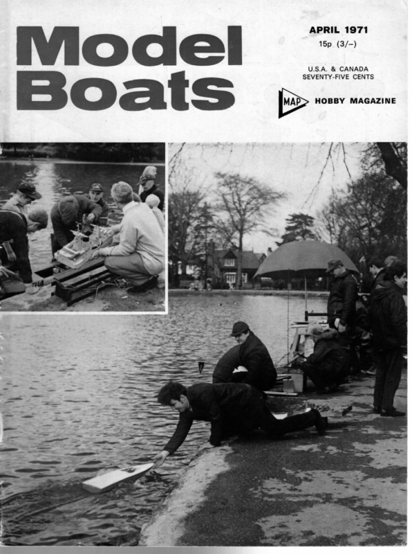
APRIL 1971 15p_(3/-) U.S.A. & CANADA SEVENTY-FIVE CENTS pu> HOBBY MAGAZINE
APRIL 1971 Juniors and Yachting There is evidence of renewed concern over the failure to recruit younger new members into model yacht clubs, and although this has been a perennial problem, it may well be that the present climate is right for some positive steps to be taken. In general, only three classes are widely sailed, the A, the 10, and the M. The rule for the A class, now about 50 years old, was so cleverly arranged that development in boats is limited; the trend to heavy- weights is a result of vane steering, modern sail materials, etc., but heavyweights are not necessarily better than moderate or even light displacement craft, and a boat built new is still likely to be competitive in four or five years’ time. However, an A boat is big, fairly expensive, and difficult to transport, and few beginners, especially young ones, would plunge in at the deep end with one of these craft. The 10-rater and Marblehead classes have much simpler rules, but development, particularly recently, has been rapid, and someone who builds a model only to find it outdated a year later can understandably get discouraged. This is why we have always supported the idea of a one-design class; it wouldn’t even matter all that much if it was a bad design, as everyone would be under the same handicap, and at least the builder would know that no major change would be likely to arise to outdate his boat completely. We understand, though, that the recent proposal for a one-design in the M.Y.A. has been turned down. Which brings us to the only other classes still recognised — the 6-metre and the 36R; the 12m. is so long gone as to be out of court. Perhaps the snag with the 6m. is the complexity of the rule. They can be pretty boats, like scaled-down As, but are still perhaps a little big and complex for a beginner at around 5 ft. or so length and 30-odd pounds displacement. The 36 in. Restricted class has been in the doldrums for the last few years, but is now beginning to be looked at hard. The rule is simple — the hull must fit inside a box of dimensions 36 x 9 x 11] in., and the all-on weight is limited to 12 lb. Punt and pram bows are barred, as are centreboards. There is no restriction on sail area, and this, we feel, is a snag. Some of these boats in the past have carried 1,100 sq. in. or more for light weather suits and the number of sail changes and the skill in handling over-canvassed models tended to decrease the interest of the beginners for whom the class was intended. A set of limits on main, jib, and spinnaker hoists and sail foot dimensions, restricting fore and aft area to, say 600 sq. in., plus a three-suit maximum, could be what is needed to revive this class. In March 1934, the M.Y.A. introduced an even smaller class —l.o.a. 30 in., beam 8 in., extreme depth of hull 9 in., displacement 9 Ib., sail area unlimited. Some delightful little boats resulted, but the class was never really popular, possibly because it was so little different from the 36. We mention it because it is a size that could nowadays well appeal to a kit manufacturer (vacuum-formed hull, etc.) and if something was available in kit form this could well be a major step towards re-awakening interest — providing clubs put on occasional races for the class and advertised them in their area. One understands the reluctance of the M.Y.A. to introduce altered or new classes with no guarantee that success will follow, but nothing can stand still, and if it doesn’t move forward it moves back; from a beginner aspect, it is surely better to have tried and In the Tideway failed — several times if necessary — than never to have tried at all? Championships A new National competition will be sailed this year —a Marblehead Team Championships. Teams of two boats, aggregate scores counting, will be racing at Witton Lakes, Birmingham, on 10/11th April. There should be some pretty sharp sailing, well worth watching. The dates of the other National Championships are: 6m M 1/2May 29/30 May Q 10/11 July 36R A 10R Witton Gosport 13 June Bournville 1-8 August Fleetwood 28-30 Aug. Poole Birkenhad (entries by 10 April) (entries by 1 May) (entries by 15 May) (entries by 12 June) (entries by 3 July) (entries by 31 July) It is hoped that the Model Maker Trophy (Marbleheads) will be held at Dovercourt in September, but confirmation of this must follow. Club Notes Full details of the 1971 ‘Mini Power Boat Marathon’ on 28/29th August at Keighley are now available from K. S. Parkin, 48 Park Road, Bingley, Yorks. Entry date for this popular contest is 18th July. Mayesbrook M.P.B.S. has, through the good offices of Barking Council, obtained the exclusive use of a fine, big workshop. This has led to a spate of new projects. Any modeller in the area would receive a cordial welcome; contact the Hon. Sec., R. J. Hunter, 13 Boleyn Gardens, Dagenham, Essex. Normal Service At the time of writing, postal disruption still continues and even when the strike ends it will be some time before postal arrangements return to normal. Subscribers in particular are affected, and we very much regret this. This month sees a gap in the Racing Model Yacht Construction series, and for this and other irregularities we can only ask your indulgence. Naviga Teach-in Maurice Franck’s ‘teach-in’ on Naviga rules has now been fixed for Easter Sunday, 11th April, at Bergh House, New End Square, London, N.W.3. There will be two sessions, 10-1 and 2-5. The object of the exercise is to familiarise British club officials and keen competitors with the rules and their interpretation, specifically to assist our team in the European Championships in Ostend in August, but also, of course, to enable clubs to get used to the rules as interpreted so that when we stage the Championships in 1975 there will be no chance of confusion through different interpretations. Incidentally, for 1975 three sites have been shortlisted, all near London since the Continentals have asked for this if possible. The possible venues are the relatively new Stanborough Lakes at Welwyn Garden City, the familiar Verulamium lakes at St. Albans, and completely new water at Thamesmead. In each case the local authority is keen and discussions are continuing. 141 eo… TMm
mn MODEL . 1 BOATS 3 —s | Simple Moving Carriage V ane 6 Gear “ (== 1 5 Q io) = | designed for ease of manufacture and is well 1° within the capabilities of the home modeller who has no access to machinery other than an electric drill. The gear is highly sensitive and is at present in operation on my own 50 in. unregistered Marblehead; if made carefully it is also quite pleasant in appear- 10 = 10 11 — abe Built without elaborate tools by T. H. Crawford A pss adaptation of the moving carriage gear is LD at ‘ HAE we u : bh A vine a\ \ 9 8 ee a —= PRES a ‘ ance. (1) Sun wheel. Meccano gear } in. dia. approx. with gear face reduced to 3/16 in.. (2) Planet wheel. Meccano gear } in. dia. approx. with gear face reduced to ¢ in. Items (1) and (2) need not have gear faces reduced, but if this is not done, the overall height of the carriage will be increased. > PLAN AT TOP, OF 2 se DISC 8 (3) Vane spindle. 5/32 in. dia. stainless steel rod with approx. 80 deg. included angle point ground at one end. This spindle should be long enough to just clear the upper pivot screws of the carrage support; make this item longer than necessary and cut to length last. (4) Sun wheel spindle. Material as above (3) but with approx. 80 deg. included angle point ground at each end. This spindle governs the final depth of the carriage. The design shown calls for this spindle to be -G 3 in. long. (5) Disc. + in. thick approx. 2 in. dia., edge to be graduated in 5 deg. intervals. This disc is drilled 11/64 in. dia. at planet wheel centre (i.e. centre of disc) and drilled to a depth of 1/16 in. at sun wheel centre. This blind hole to be just clearance of upper carriage support screw diameter. (6) Arm. 1/32 in. thick stainless steel to fit over collar of sun wheel, and be attached to sun wheel by SELF TACK a 10BA screw through both, length 14 in. from centre ARMS LOWER of sun wheel to outermost hole. Four holes 1/16 in. dia. ¢ in. apart. PLATE ONLY (7) Carriage top plate. 1/32 in. thick stainless steel (flat) with planet wheel centre drilled 11/64 in. dia. and sun wheel centre centre-popped to allow location ‘ of spindle point. (8) Carriage lower plate. 1/32 in. stainless steel 6 N OF SUN WHEEL (flat), with both gear centres centre-popped to allow location of spindles, lower plate only to have selftack arms. 1 (9) Carriage spacing screws. 6BA countersunk instrument head, stainless screws 1} in. long with nine nuts. (10) Spindle locating plates. $+ in. thick perspex, three to be made, the same shape as the top plate ; item (7). Two to be drilled 11/64 in. at gear centres | and the remaining one drilled to 1/16 in. depth at sun wheel centre to clearance hole of diameter of lower carriage support screws. (11) Carriage support. 1/32 in. thick stainless, with quadrant marked off in 5 deg. intervals to approx. 30 deg. each side of centre line. Dimensions can be adjusted. Two carriage support screws, approx. + in. long stainless with four nuts. say 6BA (12) Spacer. 1/16 im. thick brass or stainless washer I D 11 64 in, OD ? in. This spacer eliminates any upward movement of the planet wheel, which may 11 1 ‘ j | a ge SY | | | PLAN OF CARRIAGE SUPPORT ;
- Balance Weight A Sun Wheel B Planet Wheel Grub Screws Self tack arm port and stbd. Adjustable quadrant cies Tiller Self tack guides 4 in No. Self tack line port and stbd. Link See detail bottom right 1. Sun wheel; prox. 2. Planet dia. approx. 3. stainless steel Horse Meccano gear 34 in. dia. ap- wheel; Meccano gear 1 in. Vane spindle; 5/32 in. dia. rod with point ground aa one end. Sun wheel spindle; as 3 above but point each end. 5. Disc; Y% in. thick perspex disc 2 in. dia. marked off in 5° graduations. 6. Arm, stainless steel arm. 1/32 in. thick. 7. Upper carriage plate; 1/32 in. thick stainless steel with sun wheel centre heavily pop marked and planet wheel centre drilled 11/64 in. dia. 8. Lower carriage plate; material as 7 but both gear centres heavily pop marked. 9. Carriage spacing screws; 6 BA. stainless steel screws with C.K. instrument heads. Lengthen to suit. 10. Spindle locating plates. ¥% in. thick perspex shaped as top plate, but with gear centres drilled support; 1/32 rant marked Spacer; 1/16 in. 1/D 3% in. Rudder 11/64 in. dia. 11. Carriage in. stainless steel plate, quadoff in 5° graduations. 12. in. thick brass washer 11/64 O/D. “th ¢ Jack line Hook =- cary ied ~ XN Slide a vial =~ Main sheet Bowsie device. I use an adjustable quadrant but this is purely optional. All I have tried to do is produce an efficient, easily manufactured version of a complicated gear. I made my own with the aid of an electric drill, a cheap portable woodworkers’ vice, and the kitchen table. result in that wheel jumping out of the lower bearing point and causing the equipment to bind. When assembling it is important to adjust the carriage plate spacing so as to locate the sun wheel spindle in the centre pop marks, but not lock in them. This can be done by bringing plates together slowly by turning the nuts marked ‘A’ on the carriage spac- Self-Tack Operation of the Moving Carriage Gear The operation is for the boom to exert a sideways motion (say to port) upon the slide, therefore tightening the starboard self-tack line, and slackening the port self-tack line. The slide will then move to port until the carriage pointer contacts one of the nuts on the adjustable quadrant, at which point the starboard self-tack line will bring the slide to a halt. This movement of the carriage will tend to rotate the planet wheel around the sun wheel, thus bringing ing screws until the spindle cannot come out of centre pops but is not locked (this to be done with spindle locating plates in position). Planet wheel and spindle need not be used at this stage. The next operation is to install the planet wheel and spindle, allowing the spacer to come within, say, three thou. of the top locating plate; as long as the planet wheel lower centre-pop bearing is deeper than three thou., this spindle will not leave its position. It will probably be found easier to make the carriage plates, stainless and perspex, if a template is made first of stainless steel and centre holes only the vane into line with the wind direction. Thereafter, any alteration in the course of the boat or direction of wind will misalign the vane with the wind direction and the vane will execute a correction of the rudder to bring the boat back on course. At the point where the boat requires to go on the opposite tack, merely pushing the bow of the vessel drilled. The template can then be clamped to the plate which is being made and you will be sure to get the correct spacing of holes. This gear will operate efficiently for all reasonable angles of heel, but when inclined to less than 30 deg. to the horizontal, the spacer may begin to bind on the upper perspex locating plate; however, if your boat heels to this degree, there is enough wind available ta overcome any resistance which may occur in the gear! There are probably a number of improvements which can be made, such as the inclusion of a locking on to that tack will cause the mainsail to go over and drag the slide with it, which in turn will tighten and slacken the self-tack lines as described above, and cause the carriage to come over to the other nut on the adjustable quadrant, again rotating the planet wheel (in the opposite direction) around the sun wheel, causing the vane to take up a neutral position with the wind. 149 oes el
| Sa a Some Observations on Radio Controlled Yachts By American reader Frank D. Kelley prevents the boat from turning. I have seen a M to the Hammer lines dropped into the water during a blow, sail across a lake and nearly beat itself to a pulp on the far shore before the skipper could get to it, and rescue it. My own boat, a 10-r to the Flamingo lines, has done the same thing. Bringing it through luff with the rudder alone was nearly impossible. If memory serves, I managed it once in ten tries in a good stiff blow. more effect on the boat than the much smaller rudder. In one case, I noticed, the skipper was ‘pinching’ the wind, and tried to kick it through luff. He didn’t have enough forward speed to carry it through. Time and time again it fell off on the same tack, and finally wound up against the shore. Later in the day, using what little knowledge and experience I had gained with the same trouble, I tried controlling his boat. Several times he told me I was in trouble. I merely held the boat a little wider to the wind, picked up forward speed, slapped the rudder hard over, and she came through luff with little problems. I made it heel hard on a reach with the sails in tight, for a few moments while it picked up speed, so the rudder could become effective. Sail contro] is also necessary, for complete directional control in a heavy wind. Even with the larger rudder, and the near-absence of a skeg, a boat will not turn to a downwind leg until the sheets are let out. I have managed to hold wing and wing for nearly a mile as I walked alongside my boat while it was nearly a hundred yards away. No spinnaker was set, as I sailed the nearly mile-long lake for three hours without touching my boat. My sail control consists of a small motor (and a weak sister, at that), geared way down to pull a bathtub chain over a sprocket. The sheets are tied directly to the chain. As the top travels aft, it pulls the sheet to the jib in. The bottom of the endless chain, travelling forward, has the main sheet attached to it and pulls the main in. The differential in the length of the main boom and the jib club is solved by attaching the sheets at the same distance from the swivel or pivot. (please turn to page 163) im owners. These include classes as small as 30 in. L.O.A. up to and including some of the ‘A’ boats. A recently formed group, A.M.Y.A. (American Model Yachting Association) is now registering radio controlled yachts in the United States and Canada. Evidently the same slow process is going on in England and on the continent of Europe. My evidence is the article on the Mistral by C. S. Gould in the June issue of Model Boats. Some of the things we have learned about what needs to be done to the vane sailed boats to make them more suitable for radio control should be publicised. The hulls are easily adaptable for radio control, but we have found that there are a few changes necessary to make them controllable. All of the plans advertised by Model and Allied Publications, the publishers of this magazine, seem to be for vane controlled boats. If we look at what they are designed to do, they are well designed. That is, they are designed to sail in a straight line from one point to another with a minimum of swerving, and, if properly set, will go only in that direction. They are then handled (by human hands), reset, and start off on the new course. Sometimes they are pushed with a pole to change tacks, on the beat to windward. (I’ve never seen one of these races, and can only judge by what I read and see in some of the pictures.) In radio control, one of the rules is that the boat must not be touched by hand. Therefore, the change in tack must be caused by turning the rudder. We have found that merely dropping a radio into a boat with a servo hooked up to the rudder will work in light air. Notice! I said it will work in light air. When the boat is put into the water during a blow, the trouble begins. The skeg (in front of the rudder) ‘i ADIO control in model sailboats is in its infancy, but an ever-increasing number of boats are having control units dropped into them by their To counteract this tendency to remain on the same course, the skeg must be cut down, or removed entirely. The rudder area must be increased, and the total throw must be about 45 degrees either way from centre. Even then, when the sailing gets ‘hard’, many skippers discover problems. Their problem is their own lack of knowledge of the forces applied to a boat. They don’t realise that the sails have far 150
MODEL BOATS A LIGHTWEIGHT ‘A’ CLASS BOAT BY A LEADING AMERICAN YACHT (SHE concept of a successful lightweight Class ‘A’ boat (33 to 38 lb.) has been an intriguing question lying dormant within me for a number of years. At the close of the National M Race, held in Detroit in the autumn of 1969, the possibility took hold and my enthusiasm finally carried me to the drawing board. Lines were set down on paper, a split female mould, made out of wood, was constructed, and two models of glass-fibre were built. One was sold almost immediately to a retired former model skipper residing in the western part of the country, who was looking for a lighter ‘A’ boat to handle than he possessed. The other was built and sailed by a Detroit M.Y.C. skipper, who brought the boat up to a tie for first place in the 1970 National Class ‘A’ championship. While this one success cannot be construed as establishing an earthshaking precedent, it is nme \ \ Sg “ \\ A Full-size drawing available as below, price 75p inc. post nevertheless encouraging to note that it is possible for a lighter ‘A’ boat to compete against the heavier boats, especially in medium to heavy weather. It has become an agonizing belief of the author that should the era of the 70 Ib. Class ‘A’ boat and up become firmly entrenched, then the class is in real danger of becoming extinct. We may already be in a race between developing a successful lighter weight class boat or continuing on to larger and larger boats, with a corresponding drop in the number of skippers willing and able to handle them. As the weights of boats increase there must come a point of demarcation for every skipper when the extra burdens of handling overcome the pleasures of sailing. For some skippers this may be a 40 lb. boat; for others a 50 lb. boat; for others 60 lb. and for still others, 70 lb. or 80 lb. boats. Each step upward in weight unfortunately must carry with it a corres- a M | BY G.|
MAN JULLER APRIL 1971 ponding step downward in the number of skippers willing and able to participate. A breakaway, then, in our way of thinking regarding this class is called for, and Mini A hopefully may become the forerunner in the exploration of a distinct other side to the Class ‘A’ formula. It is not within the scope of this article to attempt to explain the ramifications of the International Class ‘A’ rating rule, but let it suffice to mention that because of her light weight, Mini A takes a type of penalty that still leaves her with a decent LWL (53.5 inches), but which drastically reduces her sail area (1,200 sq. in). The model yacht club to which the author belongs is fortunate in that one of its skippers does not always use the maximum allowable sail area permitted, but sails a Marblehead in lighter winds with less than 800 sq. in. of sail area and sails his ‘A’ boat with a jib that no wise fills his allowable foretrangle. He does not always win, but the lessons I 7S” WL BEAM QBL = 12-375 ACTUAL 48-0″ QBL ALLOWABLE 50 718” $35+3475+ 53543475 2 2 Yor * |-06 a successful lightweight Class ‘A’ boat. The design of Mini A is rather straightforward, of V-sections, its length overall being governed to a great extent to a length which can easily be got in and out of the boot space of an automobile. The lead keel is non-detachable. There is no tumblehome to the model because it was designed for laying up in a female mould for glass fibre construction. The designer has an iconoclast approach toward model yacht design, so if the builder of this model desires to add tumble-home, make use of a set of sails he already possesses of approximately 1,200 sq. in., or change the outline of the keel or skeg, he is certainly welcome to make the change. If one has sails for a 10-Rater it will be appreciated by the author if the skipper will let him know how Mini A does sailing against The original model of Mini A is 14 in. shorter overall than the has finer bow sections with female =3930 = 10 04 aon ~ optimism with regard to the feasibility of developing the 10-Raters. has a plumb bow, present design and a fuller transom. Nothing in the canoe body has been altered, but a more equalizing of the ends had been attempted, and with additional sheer in the bow, it is hoped she will ride better over the larger waves instead of going through them. During the second day of the 1970 National, in 30 m.p.h. winds, she showed a tendency for submarining. Fortunately, this did not slow her down much, for she did not lose a run during the two days of racing. In fact, on the day of the heavier weather, her skipper would give a boat length or two to his opponent at the start to lessen the possibility of a collision and consequent resail. As brought up earlier in this article, the model was laid up in a split mould made of wood, this being constructed on the same principle as a model built by the bread-and-butter method, but leaving the outside unshaped. The author has used this method successfully in a number of moulds for models ranging in sizes from 36 in. O.A. to a 60 Ib. ‘A’ boat. By using this system there is no necessity for building a male ‘plug’ upon which to form the 6 25″ 53:5″ LOA UWL MAX BEAM have learned from watching his boats perform have become the denominator upon which I am basing my PENALTY +20″ 10-7 yy + MINIMUM DI ACTUAL 0 <4 mould. The time required to construct a mould of this type is approximately half that of building a model complete by the B & B method, it also being possible to use a cheaper grade of timber than in a B & B model. The advantage of course is that after the mould is constructed a number of glass-fibre hulls may be taken from it. With the mould for Mini A, I also built a detachable deadwood keel section, so I was able to lay up the keel in conjunction with the body of the boat. This leaves the keel hollow down to the lead. There appears to be no saving in weight, however, although one would imagine it to be lighter than a similar keel built up of wood. In fact, the weights of a glass-fibre model come out very close to those of one built of wood, 10 lb. for the hull and appurtenances and 26 lb. for the lead keel. The original model of Mini A weighed in at 36.5 lb., but because of its well rounded bottoms of sections in bow and stern, it still measured in at 53.5 in. L.W.L. For those skippers then desiring to compete in ‘A’ boat races, yet finding present sizes objectionable due to their great weight, Mini A should provide them with the opportunity for doing so. And need I add, that there is an extra thrill in store for you when you watch your “little” one beating the “big” one over the finish line first. EE |
MODEL BOATS R/C Yachting with Metro Marine Modellers By D. A. Eason "NE Summer of 1970 was for the Sail Group of the Metro Marine Modellers of Toronto, Canada, a very active one. The members of this group have taken part in three Regattas and four Sail-Ins, as well as sailing on the remaining week-ends at the Mill Pond, Richmond Hill. I should explain that we define a ‘Regatta’ as a sailing meet where three or more races are sailed by each boat and a prize or trophies are awarded to the winners. A Sail-In is a sailing meet where we race but no prizes are awarded. All of our races during the summer were sailed with the boats divided in two classes, those under 50 in. O.A.L. and those over 50 in. O.A.L. We have raced boats this way for the past three years and have found it a satisfactory way of racing a mixed fleet. It is the feeling of the writer that for 1971 have to go to class sailing as the number of am sure, will justify it. The 1970 season opened with a regatta at May 24th. The weather was not of the best, we will boats, I Buffalo, but the sailing great, with winds in the 25 m.p.h. range, which proved too much for the under 50 in. boats. The over 50 in. boats, however, lapped it up. Taking part in the racing was a total of 19 boats made up of 10 Santa Barbara, six 10-Raters, two ‘A’ Class, and one 12 Metre. Each boat sailed in three races on the triangular course on Delaware Park Lake. The course had one long leg which proved to be a run, and to the advantage of the Santa Barbaras. What happened each time a S/B and a 10R met was that the 10-Rater would make the first mark just ahead of a Santa Barbara, then lose his lead on the long run leg. At the end of the day’s sailing, the Santa Barbaras clearly won the day, taking the first three places. With George Fine of Pittsford, N.Y., standing 1, 1, and 1 for first place, James Hoover of Endicott, N.Y., taking second place with 2, 1, and-1, and Bob Dence of Johnson City, N.Y., in third place with 3, 1, and 1. Kitchener, Ontario on June 21st, was the site for the second regatta of the season. The weather was much improved by this time. The winds were much lighter, however, also quite variable and _ shifting. The site was the lake in Waterloo Park. A triangle course was also used, with the major difference that all the legs of the course were of equal length. This was possible because of the shape of the lake. With the lighter wind, the under 50 in. boats had a good day. The top man was Jack House, sailing his boat to four firsts with Ted Robertson and his scale model of the Bluenose Schooner in second, and Frank Fearn sailing his Star Class to third place. The over 50 in. racing group also had a fine day with eight boats competing, five 10-Raters, one Santa Barbara, and two ‘A’ Class. The end of the day found Ted Robinson A Buffalo, N.Y., in first place with his ‘A’ Class 3, 1, 2, and 1, and Roy Bourke of Toronto in second ike with his 10- Rater, 1, 1, 3, ong 3. Bill Burgess and his 10-Rater placed third , 3, 3, and 1. These two Toronto boys had to have a sil: off to settle second and third place, which Roy Bourke won to secure the second place. On August 30th, at Toronto, a regatta was scheduled. The weather proved to be its undoing; after very heavy rain in the morning a start was made in racing in the afternoon, but the wind was so light that it was decided to reschedule the regatta for September 27th. The weather of the 27th was a great improvement. The winds also were very good, shifting very little and varying only in strength from 8 to 10 m.p.h. with the odd gust to 15. The course was again a triangular one set out on Grenadier Pond in High Park, Toronto. The over 50 in. group had 10 contestants, seven 10-Raters and three ‘A’ Class. The top skipper of the day proved to be Ted Robinson of Buffalo, N.Y., with three firsts. Bill Burgess of Toronto also had a great day with two firsts and a second to take second place with his 10Rater. Third place was taken by Jack Robinson of Buffalo, N.Y., with his ‘A’ Class. The under 50 in. group also had a fine day of sailing. The competition was made up of two scale Above, a close finish as Ted Robinson’s Bill Burgess’ KC110 up to the line. Left, Toronto Metro M.M. club. 158 A Class follows members of the
APRIL 1971 Right, Bob Wynne’s US119 (a Red Herring) winning against two Santa Barbaras. Below, Bill Burgess of Toronto with his Warlord 10R, winner of the 1970 Fred Mathews Trophy. Bottom, |. to r., Ashley Marshall’s 10R Moth, Norm Perkins with his Red Herring 10R, and a trio, Frank Fern’s Star, Mike Taylor’s Adagio, and Dennis Eason’s Red Herring. models of the Schooner Bluenose, four 50/800 Marbleheads, one scale Dragon Class, and one Star Class for a total of eight boats. After a complete round where each boat had sailed in three races, we found we had a four-way tie for first place. This was bad enough, but to make it even worse, three of the four were on the same radio frequency. It seemed as though Murphy’s law had proved itself again. After consultation with the four contestants, it was agreed to sail each of the four Marbleheads against a 10Rater for one lap of the course, and time the difference of lap time for each Marblehead and the 10Rater, the winner to be the one who had the smaller time difference. The 10-Rater chosen for the sail-off was Roy Bourke’s, as Roy’s boat had been the most consistent of the day, having finished in second place for each of his three races. When the four races were finished, Derek Pheaton came up as the winner by his finishing 1 min. 23.2 sec. behind Roy’s 10-Rater. Joe Lacy was second, finishing 1 min. 35.3 sec. later. Mrs. Jane Wynne from Buffalo was third, the only lady skipper, finishing 1 min. 51.2 sec. after Roy. While this is not the only way to settle a tie situation such as this, it worked out very well this time. It is to be hoped that more R/C manufacturers will come out with plug-in crystals for their units, so we will be able to work out these ties by actually racing all boats against each other. Last winter we sought a means of encouraging our club members to take part in the Regattas which the Buffalo, N.Y., Kitchener, Ontario, and our club planned to hold. The club decided to purchase a perpetual trophy which would be awarded annually. The trophy was named The Fred Mathews Trophy, in honour of Fred who was one of our founding members. The way we set it up is: a club member who competes at each of the three regattas will have a record kept of the points he scores for each race he is in. The point system used was 9 points for first, 6 points for second, 4 points for third, and 1 point for completing one lap before the end of the race. The way it has worked out has been most satisfactory. At Buffalo each boat sailed in three races, at Kitchener four, and at Toronto three. The maximum (continued on page 165) 159
WM Sed ie su = ae 7 all on MODEL BOATS iin, Yachts to recognised classes were quite a big feature at Nuremberg, most with an eye to R/C operation, as keener readers will spot by the fact that all the boats in the above pictures have fully floating rudders, without skegs. On the left is a Marblehead, Windy, on the Rowan stand. Centre, on the Fiberlin stand, another M, this one carrying a label saying that it was European Champion at the 1970 Swedish meeting. We are not clear whether this is offered as a kit, but there is a remarkable resemblance to the Stollery Mad Hatter design. The third picture shows the Klug range, glass-fibre (as are all these boats) in M and 10R size, as well as a schooner-type 63in. length and a Bermudan boat apparently only slightly under M size. We believe that a possibility of an English agent for these models exists. They are available as kits or completely built and are superbly made. TEST BENCH New items from the model trade “ FYNHOUGHT you'd like to see the latest AcMan by Palitoy, tion complete with zip jumper, laced boots, etc., which should be in the shops soon. He’s 114 in. tall, most for big rather models but ideal for a rowing boat as in our January issue. Price, because of the detailed clothing, will be £2.40. Silenced tuned pipes with a new _ heat-proof black coating are available from E.D. (64 Brighton Road, Surbiton) and tests we made showed noise on a 10 c.c. glow cut from 93 to 85 dB with a gain in r.p.m. of 1,200, running on an 11 x 7 airscrew, over open-ex- haust figures. Weight is under 3 oz. and price £5.23. Also in the picture is an adaptable manifold
aa ha gn Sa sO) SSO MODEL BOATS HEADBOARD MADE Making sails with FROM FORMICA modern materials is very much easier LUFF TAPE 1.1/4" WIDE BEFORE than it used to be. FOLDING Fred Shepherd gives 2 the procedure in on his simple 36 in. ALL CORNERS HAVE DOUBLE THICKNESS CLOTH THIS SHOULD BE GLUED IN PLACE AND Restricted design ALLOWED TO DRY BEFORE STITCHING “Square One” ANY clubmen build their own boats, but far fewer make their own sails. This is rather odd, as with modern materials there is far less involved in sailmaking than in boat building. Material (usually hot-rolled nylon dinghy cloth) can be obtained from almost any sailmaker, and some sources are listed at the end of these notes. The writer has found that 4 ounce cloth is the most suitable for model yachts, and three yards will be ample to equip Square One with a complete set. Prices vary considerably, from about 45p to 70p a yard for the best coloured cloth. A piece of hardboard about 30 in. x 72 in. will be needed for marking out and cutting, and a panel about this size can be bought inexpensively at handyman stores. The sailcloth should always be cut with a “hot wheel” gadget such as sketched, or a soldering iron sharpened to a knife edge. Neither needs to be red hot. A straight-edge 72 in. long and a few lead or iron weights to hold it steady are also required. Tape for the sail luffs can be bought in rolls, but strips can easily be cut off the edge of the sailcloth. The tapes need to be 1-14 in. wide before folding. Some difficulty may be encountered in getting the SEW HEAD BOARD TO SAIL WITH THREAD r { | ' { ' \ ' 1 | ! | | PUT BATTEN IN | WHEN THIS POINT ! 1S REACHED, THEN SEW IN ' \ ! | START HERE | ! LUFF TAPE FOLDED. ! THIS WILL PUT A PERMANENT CREASE IN METHOD OF SEWING ON LUFF TAPE AND CORNER PIECES I @ I START HERE JACK LINE HOOKS (OPENED OUT DRESS HOOKS EYELETTED IN PLACE) DRESS MAKER'S EYELET GADGET FOR MATERIAL CUTTING S FINISH HERE MADE FROM OLD ARMCHAIR CASTOR. CHINA WHEEL REPLACED BY METAL DISC SHARPENED., HANDLE |2" 3/8" GAS. MAINSAIL BACK EDGES OF ALL SAILS SHOULD ALWAYS PARALLEL WITH EDGE OF PIPE TOP SAILCLOTH WOUND WITH MASKING TAPE TO REDUCE HEAT. 164 RUN


