- STAR—C An independent report on building and sailing our 42 in. R/C one-design yacht by experienced skipper BOB JEFFRIES
- COMET Part One A 42 in. sailing catamaran incorporating a novel sheeting mechanism adaptable to other sailing craft. By E. F. Amiss
- Readers Write…

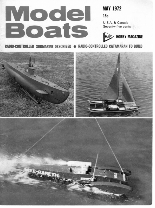
MAY 1972 15p S.A. & Canada Seventy-five cent HOBBY MAGAZINE RADIO-CONTROLLED SUBMARINE DESCRIBED @ RADIO-CONTROLLED CATAMARAN TO BUILD
STAR—C An independent report on building and sailing our 42 in. R/C one-design yacht by experienced skipper BOB JEFFRIES Re readers of this journal and its companion Radio Control Models and Electronics will know my views regarding the future of R/C yachting, and my campaign for the adoption of a smaller class, more suitable for ease of building, transport and cost than the heavy ‘Q’ class. Recently I have had a lot of fun sailing a somewhat elderly ‘M’ boat adapted to radio control. From that experience, I have designed a new boat to the ‘M’ rules, but adapted to give the best performance under radio control. Out of the blue comes the December issue of Model Boats and the announcement of the little Star C. I felt the size (42 in. overall) was a bit on the small size, but worth building and testing, in the hope that the size would catch on and become the new smaller class I have so long desired. An immediate approach to your Editor produced one of the first hulls after the prototype. All work on my new ‘M’ boat was stopped, so that work could start on this, nl speed. mass and it could be built and tested with all The hull and the two halves of the fin are in glass-reinforced plastic, and were in white, with an excellent finish that would not require painting or any further effort. The idea of building a keel that did not require casting was a good idea, and is worthy of commendation. The digital equipment in my present ‘M’ boat weighs, complete with hatch and perspex box, around 1} lb., so I decided to use the plastic sandwich box as recommended, as this would reduce the weight slightly. I allowed for 14 Ib. of gear and therefore made the fin keel weigh 6 lb. The jointing of the two halves of the fin, and the attachment to the bottom of the hull, were made with epoxy resin. The drawings stated the space in the fin should be filled with polystyrene. I was working ahead of the articles on the construction, and poured in the two chemicals that make polystyrene foam. I found later the idea was to fill these spaces with chopped-up ceiling tiles. 190
MAY 1972 Pictures opposite show Bob’s finished model on test. Note the ‘goose-winging’ centre bottom; this can be assured by using a light spring or rubber band to bias the jib, but seems to happen automatically anyway on this yacht — the original model does it, too. Above, views of the electronics, set well below deck as seen in the centre photo. One advantage of a glass hull is relatively easy accessibility, with no internal structure to obstruct reaching inside. cured on subsequent trials when the mast was moved forward. Subsequent trials were made in much more suitable weather. I found she would beat to windward really well, and would hold her course for sometimes as much as 25 yards without having to give any rudder adjustment. With the jib and mainsail about 10 degrees from centre line, she would beat to windward on either tack without difficulty. Downwind, with the sails let right out, she I think my idea, if you can obtain the chemicals, is better. The rudder was made to specification. Your Editor calls me ‘a big rudder proponent’ in this he is right. I am firmly of the opinion that a large rudder moved a small amount does not slow a boat anything like as much as a small rudder moved a larger amount, assuming the turning circle is the same in both cases. More on this subject later. The general construction calls for no comment. To keep the overall weight down, I used obechi for the deck beams and inwales, and made the deck from 0.8 mm. waterproof ply. I watched the weights of all components carefully, as it was my idea to keep the weight down to the bottom limit of the specification. In this I was successful, and actually I shall have add to weight as Iam all of two ounces below the 113 lb. As mentioned earlier, I fitted the radio equipment in the plastic box recommended, but fitted it below a hatch, as low as possible to keep the centre of gravity down. This made it necessary to fit the drive to the rudder and the rigging to the sail winch below deck level. The various fittings were all home made, were quite conventional and call for no comment. The sails were was quite easy to control and showed no tendency to wander. The rudder was adequate in all winds except very light airs when the boat was ‘ghosting’ (hardly moving at all). Then I wished the rudder was bigger. At the Boat Show at Earls Court recently I had the pleasure of sailing one of the R/C ‘M’ class yachts by Flotilla Models Ltd. in the lake, using artificial wind from a large industrial-type fan. These yachts are fitted with spade-type rudders and I was so impressed with their performance and ease of control, I decided to use this type of rudder on the ‘M’ boat I referred to earlier. I am contemplating changing the rudder on this little yacht also. The spade rudder is only suitable for use when the control is proportional. The bang-bang type of control, which gives full rudder or centre only, is too fierce to get smooth control with this type of rudder. Undoubtedly the best type of radio to use is where the control is proportional for both rudder and sail setting. I have tried sailing without using the sail adjustment, and only using full rudder or centre to simulate the use of single-channel equipment. Sailing cross wind on a figure of eight course, I found it quite simple, and would give a lot of fun to anyone with the simplest equipment. Races could be held with other yachts similarly equipped, but it will be understood that full control of rudder and sails obtained from Nylet Ltd. of Fordingbridge. This firm are local to me, and have made sails for my earlier boats for some years. They are in white siliconised Terelyne and are very well cut and finished. The radio equipment is again home made, and is based on the successful digital equipment described in Radio Control Models and Electronics some two years ago. I modified the transmitter to include tuned circuits in place of the untuned R.F. chokes, and in so doing increased the power output considerably. The rudder is operated by a Remcon Quantum servo mechanics using Horizon amplifier. The sail winch is home made, and operated again by a Horizon amplifier operating relays to switch the separate battery power to the winch motor. Both rudder and sails are operated proportionally. I sympathise with our Editor on his reports on the first trials of the prototype. I also found the weather wet, too windy, not enough wind, no time, and had to wait several weeks until a suitable occasion when weather is vastly preferable. From the few times I have sailed this little yacht (I am calling mine ‘Electra VII’, being the seventh R/C yacht I have built!) I have decided it was well worth building and will give a lot of pleasure in sailing. I see that at the time of writing, over thirty are being built. I should be pleased to offer anyone in the Bournemouth/Southampton area an opportunity of seeing mine, and perhaps seeing her sail. I would welcome to hear from anyone and available time coincided. The first trials were made building in this area, so that we could get together and have some friendly racing. Perhaps if numbers are sufficient we may start a club locally. Either drop me a line c/o our Editor or telephone me anytime at Highcliffe 4438 and have a chat. in somewhat windy conditions around force 4/5, really too windy to carry out serious trimming adjustments. My first reaction was the mast was too far back, as she would keep coming up into wind, and I found difficulty in gybing (turning away from the wind). All of which were ? 191
MODEL BOATS i a’s catamaran is a stable and speedy model which uses a two-function proportional radio and incor- porates a quick-release clutch for the sails, giving instant and complete control. It has been sailed all day without the necessity of touching it, from a deck-chair on the pondside, and however the wind changes, control remains. Deep V hulls give very good stability, and the absence of a centre cabin helps, since if the model is steeply heeled with one hull in the air, the wind can blow through the between-hull slatting and the model rights itself at the first lull, or on release of the sails. It has never capsized yet. The ‘works’, i.e. the clutch/drums/motor assembly, function is as follows: Transmitter stick Up. Servo movement pulls control rod which pivots clutch selector arm and holds it in new position till signal is released. The arm carries a fork which disengages clutch by pushing clutch plate 2 towards the motor. Clutch plate 1 forms part of the winch drum and is now free to revolve. Wind pressure on the sails unwinds the winches, and it is impossible to tangle the lines. Release of Up signal. Control rod returns to neutral and spring re-engages clutch plate 2 with clutch plate 1. Stick Down. Servo arm moves control rod in opposite direction; end engaged with clutch selector arm simply slides further through hole in arm and has no effect, but microswitch contact is made at servo end, switch- ing on motor and winding sails in for as long as signal is held. On release of signal winch switches off and sails remain in that position. If the model is at a distance, and fully sheeted in posi- tion cannot be seen, a brass bead on the main sheet is An attractive model of simple construction, this catamaran should appeal to those who like something slightly unusual. The clutch mechanism which frees the sails to blow out and locks to sheet in is shown below and on the drawing. COMET Part One A 42 in. sailing catamaran incorporating a novel sheeting mechanism adaptable to other sailing craft. By E. F. Amiss drawn up to the slotted section on the clutch selector arm, pivoting the arm, thus disengaging the clutch. The wind then tries to take the sail out and the clutch reengages, only to be disengaged by the bead, etc. This produces a loud clicking, indicating that the sails are hard home and the signal should be released, so switching off the motor. Stick left and stick right give normal proportional rudder via the second servo. For portability, the mast is simply removed by slacken- ing a knurled 6BA screw near its base, when the whole model fits easily into a car boot. With no ballast, the model is very light for its size, which is reflected in its acceleration. Altogether, an interesting project, control of which is made very simple by the clutch/winch arrangement, so why not join the small and silent brigade? 194
iV8″RBPAO:pCeINnotshf{.t}e 1“ETS SPinRETAINIDEGaed|b-2BATP! SEMLYCUHlove1=ORINSTEADUJ —_sa oCmNlPfOg—SIT[E,WIDOaAETtGBURLtpWSIrsNCecES-hmH“iin=c0>eFgP2=a7YT—wor{ |neEROaSs3i|-SeHAnF=TMOINWARLES,*9qUGGYNY— |CPEA.SFTtmihs(t>TOROBLorRED RBP. V2″ WATER RELEASE TO 8J”OIMNAERHM1U/L4″» EACHJOOINN3E1R8″SW4F»IDE = = freC)MAST PLYWO D BONDED RESIN RB.P— } 1 S C A L E T O N V I E W X P L O D . e S i A = GLUEDPYoraetHW|MEAT ortBase PLAN90°7 T aiB ERB:CK A. OR= |”REP. SID T[OECGLKU~E(8+SIDETO UNDERA,GOS TUBE ‘E8Ytuc’sWMIATKHES1|pe HERE we \’ — Po ifarl ead ‘ asro oe is ACETWINDO 1/8″ 10 TAPER ! SQUARE KE P ee eee ey os cit Tne ghe ~ ye”RPSIDES” ao on 1 39 [uw HHWrVcw=oi/awsyha1″lhJeRe”BPMpN.6&4-+HVe/UamL”rsqtQ,oHsCwsyO.+WN:lS\uTfRGhGt35.SmIKO9E=pL|[OAPNEBRVB”PaSXEURdRVS8M\”,OLXHXTNNHKRDI4TUD’EaGRnUNLeWALlECSA{VM1OS,6F”t«5r/|O8fe*_B-C&B‘TUD3—Hi—dopaxDgwsEe=ASPQ0Lt.RseA}IaTNP1LnRGPAeT3NIR9*c-0S°rG101WOVa5imlsrsNEtCe7”FKyRrAAMvEBvO&XcS_ID|f,BPP1O/l8″a)InBNsR@AZVMHMBDMAA’adHt3Cb6Hgk:”ST1O/8“S6LS8″LI—T_1o8duS-rUea2!RO1)wN);Do=eWfcIr%—|mtpPEatHuenX(eieo{W,p=CshotryRA7bSa5HAPsEj=YiJOINEs!ceOWFNMTPLT01MLHUS3HaD9re,né:,twarmRfe.,—av—Albe1I7Z:E;8″oFULC9dra|w|D|iAnGRzaguMtl{th—eNfcmip”P’)s{Fy/Ful/_ -iz bas S:|heJiMBTAwHiRn1/4o:, o”UD*LOE8— !;-—(=p9u.r1oe42eFORESA_IL—T5=4″ |JOIMNAEHR3./8″F14T Serz*vHertcs.mplaCands,fyOMMplykoEnSgtrtTeBoidg_e13°5Th MAY Rul ‘SIDES 1972 |
MODEL BOATS Main Boom | 18 in. x 2 in. dia. Mahogany or Ramin Seal for Cabin Roofs 34 ft. } in. or 3/16 in. dia. soft rubber tube (or Neoprene) Retainers for Cabin Roofs 4 Hardened brass head picture hanging pins Mast Cap Assembly 23 in. of $ in. dia. alum. rod. 14 in. of 3 in. sq. brass Pulley Housings Materials from scrap box. Gooseneck Clutch Assembly No. |. 12 in. length Z in. or | in, dia. brass rod. Clutch Assembly No. 2. 2 in. length of { in. or | in. dia. brass rod. Remainder of material parts should come from the scrap box, a chance to use up those small pieces too numerous to mention. 1/4 pint of black enamel 1/4 pint of white enamel 1/4 pint of red enamel 1/4 pint Polyurethane Varnish 1,2 ft. 6in. x 1in. thin sheet Acetate (or 1- 1 ft. 3 in. x 2 in.) Construction Begin with the keels, which can either be cut complete from 4 in. ply or each built up in three piece with scarf joints, using waterproof glue or quick setting epoxy resin. Form a slight chamfer along the bottom edges of the keels, matching the bulkhead angles. Making the hulls is a fairly long job, rather like making two boats at once, except that they must be exactly alike; it is therefore advisable to prepare all parts in pairs as building proceeds. Cut both sets of bulkheads from 6 mm. ply to shapes shown and glue to keels. While drying, prepare the four tin. x 4 in. triangular inwale lengths, retaining the 90 deg. angles but filing the faces to match angles of bulkheads. Cut notches in bows and sterns to accept, glue Straightforward construction is a feature of this model, seen above ‘in the white’. Careful alignment of hulls is essential when joining them. Materials | | | | | | | 2 Richard 6 speed 6 v. motor or similar Two-Channel propo Radio Tx and Rx (I used Futaba) Engine Servo Rudder Servo Micro Switch (normally off) 12 in. Control Rod 14in. Control Rod 6 v. Deacs (or batteries) Mast. Rigging 1313in. length3in. dia. 22G. Aluminium Tube | 342in. length 2 in. dia. 22G. Aluminium Tube I Roll fine brass picture wire (it has a steel core) Hulls Keels Bulkheads Decks Inwales 440in. 2 43in. 1 20in. 240in. 440 in. Cap Strips 440 in. x 3/l6in. x % in. Mahogany Gunwales Rudders and Skegs Rudder Bars Rudder Linkage x x x x x 44lin. x 6in. x 1/16in. Resin Bonded Ply Sin. x 12 mm. (3 in.) Resin Bonded Ply 4 in. x 6 mm. (J in.) Resin Bonded Ply 52 in. x 1/16 in. Resin Bonded Ply 4 in. xX din. Triangle Hardwood $in. x + in. Mahogany 23 in. x 7 in. xX 4 in. Mahogany 2 103 in. x in. x 4 in. Mahogany | I4in. x Zin. x Liin. Mahogany Hull Joiners 418in. x Zin. x } in. Mahogany Deck Locators for Joiners 5 in. x 3in. x + in. Mahogany Front Cross Memper 1 1Sin. X Zin. x } in. Mahogany Mast Heel Plate Slatting Slatting Supports Cabins 16in. x 23in. x £ in. Mahogany 17 5 in. x 3/16 in. x 4 in. Mahogany 179 in. x 3/l6 in. x 4 in. Mahogany 17 23 in. x 3/16 in. x % in. Mahogany iein. x $ in. x % in. Mahogany or Ramin I sq. fe. Resin Bonded Ply ¢ in. Cabin Roofs, Hatches Porthole Frames Net Stern Tubes I sq. fe. 1/16 in. 46in. x lin. x 22in. x Lin. x 2 din. x 14in. Resin Bonded Ply giin. White Perspex or Oroglas 4in. White Perspex or Oroglas x 4 in. White Perspex or Oroglas 7 yds. $i in. dia. Nylon Cord | doz. small brass screw eyes | 12 in. x 2} in. dia. brass tube | 12 in. x Zin. dia. brass tube and pin in place, cutting off surplus. It is advisable to drill the strips at each bulkhead position to prevent the pins poe splitting them; use } in. or $ in. veneer pins. Leave to dry. The hull sides are now prepared by marking and cutting out the top profile only, leaving overhang elsewhere. Glue and pin one side of each hull in place, holding the top edges with clothes pegs. It should not be necessary to steam or soak the ply, especially if the sides are cut with the main grain vertical. Trim the excess material from bottoms and ends when the glue has hardened, and repeat for the other sides. Soak and steam to shape the $ in. x § in. mahogany gunwale strips, trim to length, and glue in place flush with tops of hull sides, clamping with clothes pegs. Cut decks to fit and line with ball-point pen or marking pencil, etc., then glue in place and weight down till set. Cut the cap strips to fit, glue flush with tops and again hold with clothes pegs. It is not necessary to steam these. The top edge of the hull should show three flush timber edges, the ply side skin edge sandwiched between the gunwale and the cap strip. To complete the hulls sand the keels flat and smooth, and drill and file the scupper slots at deck level; these allow stray water to run off the deck immediately. Mark the hull centres for the four 18 x # x 4in. joiners and the front cross-member. Make cut-outs to fit them (in the above-deck projections on the inboard sides) and try to keep them a tight fit. Position the hulls accurately the correct distance apart, trim joiners to fit, and glue to decks, holding with weights. Check carefully that the hulls are parallel and square to each other in all respects. Cut the 16-5 in. lengths of $ x 4 in. to exact length and glue to decks andj oiners, again weighting. Trim the six 9 x 4 x 4 in. slatting supports to exact length and gluein place, clamping with clothes pegs and leaving a + in. step in which the slats will rest. (To be continued) 196
MAY Several readers have asked for a STAR-C 42 in. one-design R/C yacht i. Hull. Boats will normally be built using the g.r.p. hull and fin obtained from an approved manufacturer. Where a competitor wishes to enter a hull built in any other way, he must offer for inspection a copy of the hull lines (i.e. a print of the designer’s lines) plus two female templates, viz. a full hull lower profile, including fin keel, and a hull section at station 5, cut in card, ply, metal or other semi-stiff material. 2. Sails. Only sails of the dimensions specified in the original design, measured as simple head-tackclew triangles, may be used for competition pur- poses. (Jib 36 x 334 x 10, main 45 x 47 x 15). Any roach shall be contained within a fair curve not exceeding 14in. from the chord line at its maximum width. 3. Mast. Must be of circular section throughout. 4. Displacement. A boat shall weigh, in complete sailing condition, between 11} and 124 lb. 5. Ballast. Movable ballast is prohibited. Weight or position of ballast may not be altered during a race or series of races. 6. Rudder. No restriction is placed on type or area of skeg or rudder. 7. Bow bumpers. May not extend more than jin. forward of stemhead nor more than 1 in. below gunwale level. 8. Sail battens. No restriction is placed on sail battening or stiffening, except that the headboard base shall not exceed in. 9. Sail marking. The class mark shall be a circular letter ‘C’ of approximately 2in. diameter and 5/16in. thickness enclosing an irregular fivepointed star. The boat number shall be carried immediately beneath, the whole to be in the upper third rating rule. Here’s our suggestion 10. Tolerances. The eligibility of a boat departing in a minor way from the rule is at the discretion of the officials organising a race, who must be satisfied that any such departure is inadvertent and not intended to secure unfair advantage. The above is the proposed rule covering the Star-C one-design class. It should be clear that the aims are to ensure that similar hulls carry similar sails at a similar waterline length. A builder of a wood boat cannot pinch waterline length by adjusting the profile, nor can he substantially alter the waterline by moving the fin and re-trimming. There is no ‘plus or minus 4in.’, which allows a builder to build to the maximum; }in. on all sail dimensions would add about 13 sq.in., or 2} p.c., to the sail area, which could make a difference of several feet in a race. On the other hand, it is admitted that absolute precision is unlikely, but the onus of allowing a genuine variation or debarring a deliberate attempt to step outside the spirit of the rule is placed on the officials on the spot. Because a skipper with seven or eight suits of sails (or even three or four) is a quick way to put off a newcomer, we are sticking to one suit; as mentioned, the prototype sailed in a full gale and remained controllable, so there will be little chance of a race being washed out. There is nothing to prevent the development of reefing gear! A circular mast does not tie a builder on material, but prevents a gain of unmeasured area and keeps the cost down. A spade rudder can be used if desired, while freedom in sail stiffening allows one field of possible development, and the one in which experiment could well be most fruitful. The roach restriction prevents the use of junk-type fully-battened sails or other means of secur- ing unmeasured area. We hope that this covers it, but if there is any glar- ing omission, please tell us! of the mainsail. R/C sailing are limitless, let’s all get together with some boats and discover Readers’ Write… J them. J. E. Dowling Cardiff ‘ Dear Sir, Dear Sir, on R/C yachts that | felt | must put my the March issue, on the subject of the award of the Bronze to Mr. Avis’ model of the Dover Lifeboat, may | read the February Model Having Boats, | felt so depressed by the letters thoughts down in writing. The letters nearly all illustrate the eternal bickering that surrounds the organisation of R/C yachting in this country. One letter decries encouraging more than one class, another decries one-designs (why are full-size one-designs by far the most popular?). Regarding Mr, J. King’s remarks in offer a word or three? As a model maker myself for many years, and having afforded Mr. Avis some small assistance in his prepara- tions for the construction of the model in question, | was naturally interested s hasten to — and in Mr. King’s remark clinations differ, about size, type and add that | accept and respect his opinion on modelling matters without and sail. We have the Star-C, the Solent, how about a restricted class by But, as second Cox’‘n of the Dover Lifeboat, | feel qualified to comment on his The point is that opinions and in- restriction. Let’s not argue, let’s get on someone like Roger Stollery? Personally, | would like to see at least three one-design classes and a couple of restricted classes for those with more design/building time. realise that over-splintering the interest is undesirable, but | believe that there is enough interest for there to be this many classes in a year’s time. Helms- men with any ambition always gravitate to a class where the competition is hottest, so things will undoubtedly find their own levels. | demonstrated my Solent to a crowd of University sailing friends, who immediately grasped the possibilities of R/C. sailing, Team racing, 3 per side (one-designs a must), inter-club, interuniversity, national. The possibilities for ; argument. statement that the ‘lifeboat feeling did not register, Perhaps because this type of boat is not of the traditional pattern that we all know and admire’. Mr. King is no doubt thinking in terms of white end-boxes, varnished mahogany shelters, liberally sprinkled with highlypolished brass. While | agree that these boats make 1972 wonderful subjects for models and are what most people think of when they hear the word ‘Lifeboat’, may | assure Mr, King that the 44-foot steel boat in question i bp petted is a lifeboat. Designed and developed for that one and only purpose. It must also be said that if one ex- amines such subjects as speed, range, stability, manoeuvrability, assistance capabilities, etc., the ‘traditional’ types 201 do not compare too favourably. If the R.N.L.I. stuck to traditional designs, we would still be taking oars, wearing cork lifebelts and waiting for the railway horses to arrive before we could launch the boat! No sir, lifeboats, like just about everything else, are changing all the time, some of them even less like traditionals in appearance than the Faithful Forester. But they are all definitely lifeboats, and so could hardly register any other feeling. | hope Mr. King can see what | mean and that he accepts my remarks in the way they are intended. Frank P. Ide Dover Dear Sir, As a supplement to my last letter re scale models, | would like to draw your readers’ attention to the versatility of Messrs. Darnell’s glass-fibre hull of a trawler, price £7,50 inclusive. (This is a 534 in. hull to M.A.P. Gleaner drawings — Ed. 1 have just completed a model from this hull of a trawler, not the type for which it was made, but one of the Constant Star, by R. A. Sweet, whose drawings were for an 18 in. model. The hull is capable of these modifica- tions because of the good, basic design. | intend to build a modern coaster later on from this same hull. A breakdown of the cost in time and materials makes interesting reading for those who say that they have not the time. | received the hull about six (continued on page 212)


