- SHEET WINCH FOR R/C YACHTS A slightly different approach by T. B. ROSE

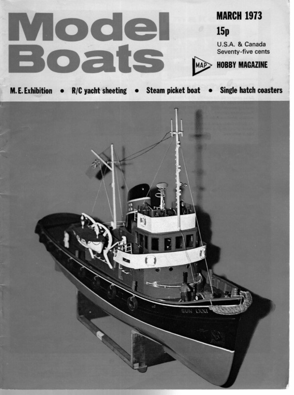
MARCH 1973 Model M.E. Exhibition @ R/€ yacht sheeting @ Steam picket boat =: U.S.A. & Canada Seventy-five cents ¢ Single hatch coasters
MODEL BOATS SHEET WINCH Winch drum m FOR R/C YACHTS \ mn Cree, A slightly different approach by T. B. ROSE ‘cere _t Fe CAN Rack and | pinion carries the winding drum and the object in this case was to make it revolve through 15 revolutions and to provide facilities for reversing or stopping at any aaa point within these limits. At the end of the shaft D is a worm, F, which drives a 60-tooth wormwheel, so that when the shaft D has made 15 revolutions, the wormwheel will have revolved a quarter of a turn. This wormwheel is coupled to the commutator B, which causes B to revolve when the shaft D rotates. This causes the brushes attached to B to rotate around the commutator A until they arrive at the insulated slots, which discontinues the supply of current to the motor and stops the winch. If the commutator A is then moved by the servo, the brushes will again make contact with the copper segments, and the motor will start up again in forward or reverse, according to Rotating brushes To servo | the position of the servo. If you have succeeded in following the description so far, you will realise that the brushes will always seek out the insulated strips on the commutator A and then the motor will stop. Because the position of these slots is under the direct control of the servo, it follows that the winch revolutions will automatic- N I became interested in the subject of R/C model yachts, the need for some kind of sheet winch soon became apparent. I looked through back numbers of Model Boats to see if I could find anything suitable, but could not find anything that appealed to me. After thinking about the problem for some time, I hit upon the following solution, which may be of general interest. The idea is so simple that it is difficult to believe that it has not been used before, but I have asked a number of model boat enthusiasts and none of them had seen anything ally be regulated accordingly. When the brushes have reached the insulated strips, the battery is automatically switched off and the winch drum cannot be revolved by pressure from the sail because the worm gear E cannot be driven backwards by the shaft D. This means that the winch control stick on the transmitter can be set at the required position and the operator can then concentrate on rudder operation through the second channel, while the winch gets on with the job and switches itself off when it reaches the desired position. similar. Although the idea is simple, it is not very easy to describe, but perhaps the diagram will help to make it clear. The heart of the system is a commutator, A, which has two longitudinal slots isin. wide which divide the commutator into two segments. These slots were filled in with thin strips of vulcanite, which were carefully filed until they blended smoothly with the curvature of the copper tube which forms the The ratio of reduction between the motor and the winch shaft can be varied to suit the power of the motor without affecting the timing of the rotating brushes on B, which depends on the ratio of the second worm gear F at the end of shaft, i.e. 60:1. It is necessary to determine the length of the sheet to be hauled in between the extremes of running before the wind and sailing close hauled. Once this length has been found, it is easy to calculate the diameter outside of the commutator. This commutator is then mounted so that it can rotate freely on a shaft and it is coupled by means of a crank or rack and pinion to a coupling rod and thence to the arm of the controlling proportional servo. Most proportional servos seem to work through 90°, so that this arrangement will enable the commutator to be turned to any point within an arc of of the winch drum which can take up this length in 15 revolutions. If L is the required length in inches ae D is the os diameter of the drum in inches, 90°, i.e. a quarter of a revolution. Two sets of brushes make contact with this com- then mutator. The first set are coupled to a battery so that the two halves of the commutator are kept at battery 47.1 A few notes on the construction of the various parts may be of interest. The commutators A and B were potential. The second pair of brushes are mounted on a second commutator, B, in such a manner that they are in line with the shaft and make contact with commutator A. These brushes collect current from the commutator A and energise the motor, C, which drives the shaft D through a worm reduction gear, E. This shaft made from 4 in. O.D. copper tube which was secured by Araldite to a vulcanite bush. In the case of B, all that is necessary is to make two slots right through the copper at 180 deg. with a hacksaw to divide the copper into two segments. In the case of A, these slots need to be made 3/16 in. wide and it is advisable to 104
MARCH fill the slots with vulcanite strip and then file up flush with the copper. The brushes were made from phosphor bronze draught excluder strip and were hammered carefully to improve the spring. Existing worm gears could probably be adapted, but I cut my own in the lathe, using a ¢ in. Whitworth tap as a hob. Both wormwheels are 1 in. O.D. I gashed them carefully to 60 divisions to give the tap a start. The blank was then mounted on a ¢ in. dia. vertical shaft secured to the cross slide so that the centre of the blank was ievel with the lathe centres and free to rotate. The } in. Whitworth tap was mounted in the chuck and the blank was gently fed in, causing the blank to rotate until teeth of the required depth were generated. The result was very pleasing and so 1 decided to make a 40-tooth wheel and use it in conjunction with a }+ in. Whitworth screwed rod as a rack and pinion to connect the servo with commutator A. This can be done equally well with a crank and connecting rod, but the worm has the advantage that the setting can be adjusted by rotating the screw which is acting as a rack, The worm wheels were made from brass and the worms themselves were simply short lengths of 4 in. dia. mild steel rod screwed to + in. Whitworth. 1973 The idea has been tested and works well, apart from minor teething troubles. There is a slight tendency for the sheet to tangle with the drum housing, but it is hoped to eliminate this difficulty on Mk. 2 by having all the mechanism inside the hull except the drum, which will have a vertical shaft. The drum on the upper deck will have an anti-tangle housing like a fly-fisher’s reel, and the sheet will be led back through an eye which will have an anti-fouling contour, near the stern. In strong winds perhaps a slightly larger motor would be better. I used an Orbit 305, but the next size bigger would probably be better. The unit is compact and gives fully proportional control and I think it shows great promise for future development. All the moving parts are directly coupled and work from a single control without the need for clutches or external limit switches. The tests were made on a yacht one metre long which I made in Germany at the end of the war from timber salvaged from the remains of the Naval dockyard in Kiel. It was designed for straight running with a substantial skeg which hinders a quick turn, and no doubt a better performance would be obtained from a hull specially designed for radio control. (F) and returns to an anchorage point at G. This should be under slight tension when the sheets are fully out so that the winch is winding in against the pull of the elastic. This prevents any tangling of the ULTRA-SIMPLE SHEETING SYSTEM An old friend from the Winchester area, Guy Batho, mentioned recently that he has been sailing for two or three years with a Conrad design using the simplest possible winching system. This uses the Monoperm motor with Richard gearbox which is easily available and which we have mentioned as suitable; it has six optional gear ratios and though these are spur gears, there is no tendency for the sails to ‘unwind’ the winch back through the gear cluster. Guy uses a simple drum made from two Meccano system. The winch motor is switched by microswitches operated by a self-centring servo, and in this instance the radio is an old RCS reed type which has given sterling service. A similar servo can be used on the rudder, but some yachtsmen find a_ progressive (throttle type) servo better for a yacht rudder. With proportional equipment standard servos can be used, throttle for winch switching and rudder on rudder. bush wheels (part No. 24 or 24b) mounted on the gearbox output shaft (on which they are an exact fit), bush to bush (Aon the sketch). The motor unit is mounted inside the hull, low down with the R/C unit and batteries. A single line from the drum passes up through an inclined tube B, cemented in the deck aft, the outboard end being above deck to exclude The switching circuit (to use one battery) is as shown in June 1972 Model Boats. Since the Conrad is a 25 lb., 48 in. w.l., 11.4 in. beam and 845 sq. in. sail area design, there is likely to be little problem with regard to room or power in a normal Marblehead. Weightwise the motor/gearbox is just over 4 oz. and it needs a 4}v. current supply (6v. has been found unnecessary) which can be dry battery or Deacs. With receiver, two servos, switching gear, and Rx batteries, it is not difficult to achieve a total radio weight of 14-2 lb., well within reasonable limits for a Marblehead. The winch and extra switches cost under £5, so this is indeed an inexpensive and water. The line passes round a pulley (or through an eye) and turns forward, separating into. two at point C to provide main and jib sheets. These operate in the normal way, turning through eyes at D and E and hooking to the booms at points equidistant from the pivot point of each boom. A piece of hat elastic is attached to the line at C and runs right forward to a pulley or eye in the bow simple way to go. 105


