- One Approach to Yacht Design A simple mathematical method of designing a yacht hull from predetermined values of displacement and Prismatic coefficient by Ben A. Hogensen

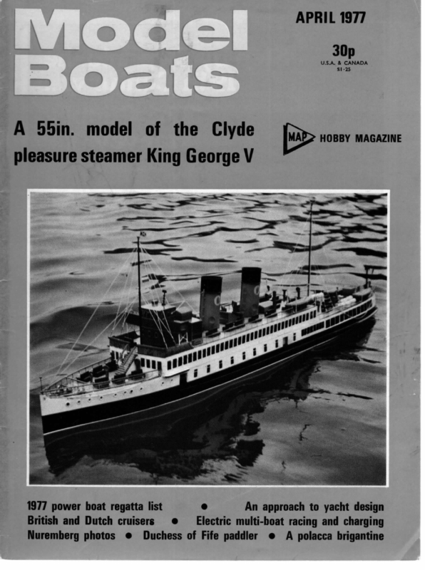
APRIL 1977 30p U.S.A. & CANADA $1-25 A 55in. model of the Clyde HOBBY MAGAZINE pleasure steamer King George V 1977 power boat regatta list British and Dutch cruisers Nuremberg photos @ & e@ An approach to yacht design Electric multi-boat racing and charging Duchess of Fife paddler @ A polacca brigantine
APRIL inserted, then they were glued and dowelled in place, suitable wooden pads being fixed to the deck underside. The anchor davit is quite simple, the only tricky part being the two blocks. I never knew how many parts a block had until I made one. However, it can be a nice piece of watch-making, as LBSC would have said. The radar scanner was made in wood and brass to the measurements given in the Decca brochure and very well it worked out too. It was suitably painted and lettered with the word ‘Decca’ on each side. I made the mast from brass tube and cut two slots at right angles about 24in long from the top to about where the yardarm would go. These four parts were then gathered into a small brass ring to give the mast a suitable taper. Small holes were drilled for the rigging. A hole for the yard was drilled and this was fitted. The whole thing was then fixed together with solder including the brackets for the three lamps. Small wire loops were soldered to the yardarms to take the signal halyards. The lamps were sawn and filed from brass tube with one end blanked off by a small piece of brass fixed by solder. A small strip of plastic film was inserted in the open end to serve as the lens. The lamps were then fixed to the mast brackets with epoxy. I would have liked to have working lamps but was put off by the thought of all that delicate wiring. Isn’t this a subject for some thought on fibre optics? Now the lamps ona pilot vessel’s mast are somewhat special. The top one is white and must be a shape that makes it visible all round. The bottom one is red and the same conditions apply. I made it from larger diameter tube than the other two, so that a small portion of red lens was visible each side of the mast when viewed from dead astern. These are the right colours of a pilot vessel on station. The lamp in the centre, of course, is the usual Siig light burned along with the other navigation ights. The mushroom vents dotted about the superstructure were all made from rivets, slices of tube and washers. oles were then pushed into tight fitting holes in the cabin roofs. Small pieces of brass wire were soldered to two tin brass screws which were then screwed into the inner sides of the ventilation trunking at the after end of the wheelhouse. These made suitable cleats for the signal halyards. The large flat-topped mushroom vent on the coach roof is, I think, the air intake for the main engine. I made this 1977 from an end cap of a large electrical fuse which happened to be the size needed. This was soldered to a length of brass tube with a big copper washer serving as the mounting flange. The other smaller vent was made in the same way. On the full-size craft it supplied air to an auxiliary generating set. The Paxolin tube from the large fuse was fashioned into the life-raft container by plugging it with balsa end caps. The moulded reinforcements were suitable cardboard strips glued in place. Hatch and door handles were made from alloy and polished up. After glueing them into holes drilled they were varnished to prevent tarnishing. The ensign staff was fashioned from }in brazing rod. Two cleats were soldered to it, for the aerial and the ensign halyard. These were run through holes drilled just below the finial cap. I made the hand rails from yin in brazing rod threaded through commercial ;;in split pins. These were all soldered together with a washer at the bottom end and mounted as a complete unit. In this operation the fixing holes in the cabin must be carefully marked out. The rails at the fore end were made in much the same way except that the joint between rail and stanchion was soldered after the assembly was mounted in place. This entailed sliding the two ends through the commercially bought knobs previously screwed into the sides of the wheelhouse. While soldering this part I covered the woodwork, which was painted by this time, with wet toilet tissues for heat protection. The only other point I might mention and I have never seen them on any other model, unless functional, is that I fitted dummy exhaust outlets, one on the transom for the st engine and that for the generator on the starboard side. All lettering and draught marks were done by using one of the dry print systems, and then varnished. The bow fender was crocheted by my mother from a length of rigging cord. At last, after what seemed to my wife a long time, it was complete. But as all model makers know, some things don’t get the priority they deserve. I have sailed the model running free, with my wife and daughter as mates, and can report that it has an excellent turn of scale speed. Ina slight chop it looks very realistic on the water. I suppose the next thing I’ll have to do is cut bits out of it to install speed and rudder control — by radio, of course. One Approach to Yacht Design ECENTLYa letter was received from Vic Smeed which said, in part, “Thank you for your letter, the interesting drawing and also a copy of your letter to Ed Williams which showed a very interesting approach to design . . . The Williams letter would form a most inter- esting basis for an article; all it requires is . . .” So — I’ve picked up the gauntlet — so to speak — and here’s the step by step process that I go through in establishing the size of a hull for a model yacht to meet a predetermined displacement. But before we get into discussing the actual figuring, may I say that my method is based on the fact that there is a definite sum of products for a given displacement that is determined by the length of the load water line, and a related sum of moments for that sum of products that is determined by the moment arm for the centre of buoyancy when Simpson’s Formula is used as the basis of the calculations. 201 A simple mathematical method of designing a yacht hull from predetermined values of displacement and prismatic coefficient by Ben A. Hogensen
SIDE VIEW at WATER LINE [Fi \_ VIEW 7) sion of the calculations). MAXIMUM CROSS 7 SECTION IN WATER EXTENDED MAXIMUM Step 5: We are not quite ready to calculate the sum of moments since the moment arm for the centre of buoyancy has not been calculated. However, we do know the displacement and the load water line length and with this information we can calculate the sum of products. It is calculated by the use of Simpson’s Formula as follows: SHADED AREA SHOWS PROPORTION OF HULL CROSS SECTION IN WATER Displacement =3 x Sum of Products Prismatic Coefficient Now -for thatstep by step walk through the calculations: When Tiny Tim was designed, it was desired to have a boat for the A Class that weighed approximately 45 pounds and had a prismatic coefficient of 0:60. Displace- ment was to be the minimum allowed for the load water line length. With this for the design criteria, the following steps were taken: Step 1: As I see it, the best place to start is to calculate the displacement in cubic inches and then find the cube root of the displacement, since both the displacement and the root are the basis of subsequent calculations. The displacement was calculated as follows: Displacement = pce pu 0-0360 __ 45-00 Weight ll tl 0-036 = 1250 cubic inches approx. Note that we say the displacement is approximate. Although it is exact for the weight given, it is approximate for the design. Step 2: The next step is to find the cube root of the displacement that will be used in the rating calculations for the model. The basis for these calculations is the displacement found in Step 1, and the calculations are as follows: Displacement?’? = 12501 = 10-77217345 = 10-80 (rounded off!) Since the cube root was rounded off, the displacement now becomes: Displacement = 10-80° = 1259-712 cu. in. A check of the weight shows: Displacement x 0-036 Ht 1259-712 x 0-036 45-349 pounds — acceptable Step 3: Since we have found the cube root of the displacement, the load water line length can be calaculated (from the A Class rule) as follows: Displacement’’* — Load Water Line min By transposition : 5 OBE Loud ater pee Displacement*’*—0-40 Displacement = Load Water Line x Area of Master Section x Prismatic Coefficient heen 2 Displacement = — x Sum of Products By transposition: ; 4 ; Sum of Products = LWL x Displacement _ 24 x 1259-712 i 52:0 = 581-405 Step 6: Since we now know the sum of products, all that remains to be done before we can calculate the sum of moments is to determine the moment arm for the centre of buoyancy. Now- since a fine entry is desired and a bustle will be used, the centre of buoyancy will be placed midway between Sta. 5 and Sta. 6 and the tentative moment arm will be 29:25 + 0-020. The sum of moments is calculated by the use of Simpson’s Formula: h x Sum of Moments Moment Arm = Sum of Products This formula is Simpson’s Formula in general terms. When the load water line is divided into 8 sections, the formula can be rewritten: Moment Arm — LWL x Sum of Moments ow 8 < Sum of Products Sum of Moments = at 8 x Sum of Products x Moment Arm LWL 8 x _ 581-405 x 29-25 52-0 = 2616-332 Step 7: At this point we know the area of the master section, the sum of products and the sum of moments. Therefore, all of the necessary information is at hand and we canset fortha set of tentative areas for all of the sections. Thomas Moore, in his book BUILD A WINNING MODEL YACHT (Frederick A. Stokes Co., 1928), used a very neat method of working up the areas that make it possible to keep a running check on the displacement and the moment arm for the centre of buoyancy. The calculations for the tentative areas of the sections = 10-80—0-40 = 10-40 Load Water Line= 10°40 x 5 = 52-00 inches Step 4: The area of the master section is found as follows: By transposition: This formula is Simpson’s Formula in general terms. When the load water line is divided into 8 sections, the formula can be rewritten: Displacement ~ Load Water Line x Prismatic Coefficient 1259-712 ~~ 52:0 x 06 = 40-375 square inches You will note that the prismatic coefficient had been specified in the design criteria, the displacement found in Steps 1 and 2, and the load water line found in Step 3. Therefore the homework had been done so Step 4 could be taken. (More on the prismatic coefficient after the conclu- 202 were done by the Moore method and are as shown below: Sta. Area xX SM = Product SM = Moment No. 1. 00-000 1 000:000 0 000-00 2. 3-750 4 15-000 1 15-00 3. 22-750 2 45-500 2 91-00 4. 31-351 4 125-405 3 376-22 5. 40000 2 80:000 4 320-00 (Master 6. 40:375 4 161:500 5 807-50 Section) 7. 35000 2 70:000 6 420-00 8. 21-000 4 84:000 7 588-00 9. 00:000 1 000:000 +8 000-00 Sum of Products = 581-405 Sum of Moments = 2617-72 Check: Disp] = 581-405 = 581-405 — acceptable 2617-72 x 6°50 Moment Arm = a acceptable a
APRIL Suppose we have a displacement of 1250 cubic inches and a load water line length of 52:0 — but one boat has a coefficient of 0:60 and the other has a coefficient of 0-40. He vlan the formula for displacement given above, we As you can readily see, only one set of calculations is used to find the displacement and the moment arm simultaneously rather than a first set of calculations to find the displacement followed by a second set of calculations to find the moment arm and the centre of buoyancy. There is a disadvantage to finding the displacement first and then finding the moment arm afterwards. This lies in the fact that quite often although the tentative section areas will give the desired displacement, they will not be proportioned so that the desired moment arm and nd: 1250 = 52:0 x 0:60 x 40-064 square inches 1250 = 52-0 x 0-40 x 60-096 square inches You will note that as the prismatic coefficient decreases the master section increases in area when the displacement is constant and the load water line length is constant. This means that if too high a coefficient is chosen that there may not be sufficient area in the master section to use a section with good lateral resistance characteristic. And therein lies the pitfall of choosing too high a prismatic coefficient centre of buoyancy is obtained. It should be noted that, with either method, when the calculations are done in advance of drawing the lines it is quite often necessary to make adjustments to the calculations when the lines are faired. What is desired is a hull with smooth flowing lines! If the calculations do not give this, it is best to adjust the calculations to the lines when they are smooth flowing and perhaps make a small compromise or two to the design criteria if necessary. After all, it is the hull and not the calculations that is going to be on the pond. under these conditions. However, there are conditions when a high prismatic coefficient will be of benefit and a low prismatic coefficient will be detrimental. Suppose we have a load water line of length of 52-0 inches and the area of the master section is 50-0 square inches — but one boat has a prismatic coefficient of 0-60 and the other has a coefficient of 0-40. By using the same formula for displacement, we find: I find that by finding the area of the master section, the sum of products, and the sum of moments in advance, I have established the basis to work from when sketching up the lines. The area of the master section lets me sketch in that section and thus know the size and shape of the largest section. Knowing the sum of products lets me keep a running check on the displacement — too low a sum means an 1977 increase in section areas is required; likewise too high a sum means a decrease in section areas is required. The key to increasing and/or decreasing which sections lies in knowing the sum of moments. Too low a sum means that the moment arm will be too short and that sections in the bow may have to be decreased along with increasing sections in the stern. Too high a sum means the reverse is true — sections in the bow may have to be increased along with decreasing sections in the stern. And therein lies the beauty of Tommy Moore’s method of working up the sum of products and sum of moments simultaneously. A knowledge of the sum of moments and thus the location of the centre of buoyancy is also used to locate the centre of gravity of the ballast. It is also used when the fore and aft stability calculations are made. To calculate the tore and aft stability characteristics, the same process is used as Step 7. Only this time the sections are drawn with the boat heeled and location of the centre of buoyancy found. Ideally, there would be no difference in the location of the centre of buoyancy when the hull is at rest in the static position and when the hull is heeled while sailing. Therefore, the final fairing of the lines is to adjust the sections so there is no difference in the length or very little difference in the length of the moment arm for the centre of buoyancy. Now that we have walked through the calculations for Tiny Tim and have completed our comments on the importance of the various parameters, we can turn our attento the promise made in Step 5. In his letter, Vic went on to say: “all it requires is a small amount of interjection as to the advantages of a high or low prismatic co-efficient, why you need to work out moments and how it might be necessary to change station areas to get flowing lines whilst still retaining the correct sum of products.” To fully discuss the effects of the prismatic coefficient would be quite lengthy — so, I’ll limit this discussion to what I consider two of the most important aspects when a prismatic coefficient is used in the calculations. Let’s go back to the formula used in Step 4, namely: Displacement = Load Water Line x Area of Master Section x Prismatic Coefficient 52:0 x 50:0 x 0:60 = 1560 cubic inches (56-16 lbs) 52:0 x 50-0 x 0:40 = 1040 cubic inches (37-44 lbs) You will note that as the prismatic coefficient decreases that the displacement also decreases since the other factors are constant. By the same token, as the prismatic coefficient increases the displacement also increases. This means that when the master section is of sufficient area to have good lateral stability characteristics that the prismatic coefficient only affects the displacement under these conditions. If too low a coefficient is chosen, the desired displacement will not be achieved. Daniels and Tucker in MODEL SAILING CRAFT say: “The use of co-efficients of fineness is really only for purposes of comparison, and a great deal of experience is needed before they become of any use to the designer. The beginner is, therefore, advised to be very chary of their use, as without the necessary experience he may be led astray.” Yes — the prismatic coefficient can be useful in preliminary calculations and as a reference for comparison of designs. But so far I haven’t defined what it is, and since there may be those who are unfamiliar with the term, let’s define it without any further delay. The prismatic coefficient is the ratio between the actual displacement of the hull in cubic inches and the displacement of a regular prism in cubic inches whose length is equal to the load water line in length in inches multiplied by the area of the master section in square inches. (Bill Daniels says it another way: “The Prismatic Co-efficient is the ratio that the actual displacement bears to the volume of a solid block equal in length to the L.W.L. and having a transverse sectional area and form equal to that of the immersed midship section of the yacht.’’) Yes — the prismatic coefficient is only a ratio between the hull and a theoretical prism. There are more important factors in designing a hull. What is desired is a sleek canoe body that offers little resistance coupled with a keel designed for a low placement of the centre of gravity of the ballast for good lateral stability. It is unwise to sacrifice good design for the sake of a theoretical ratio. In conclusion, I hope the walk we took together step by step through some of my calculations will help you formulate a method of working out your own designs — and please remember it is unwise to sacrifice good design for 203 the sake of a numerical value. IfI can be of further help, a letter to me at Box 218, Greenbelt, Maryland, 20770, USA will bring a prompt response.
MODEL BOATS varnished or painted, and in fact looked like racing yachts. I am not in any way saying that the yachts of today are not better but why have they got to be convex decks suitable only for glass fibre construction? So what I would like to say is, Come on all you clever lads, Shepherd, Stollery, Dicks, Lewis, Sykes etc. How about designin g some up to date competitive M/Class yachts with flat decks suitable for wood or glass fibre con- struction? The number of times at Meetings that we have been asked for advice, from members of the public, regarding decent upto-date designs that the average man can build very little assistance. So come on all you Southampton C. Edmondson SAIL C.E. (1) Dear Sir, P. Whitehead’s letter is interesting, but there are some lessons to be learnt from full size boat and dinghy sailing. In a squall or gust of wind the centre of effort on the sails moves aft, so the boat tends to luff up into the wind. Further, as she heels the underwater shape, pregnant -inthe-beam, may be such that she tends to bury her nose and lift the stern so that the lateral centre of pressure of water on the lee side of the hull, counteracting leeway, moves forward increasing the trend to luff up. A racing dinghy sailor knows, when a gust occurs, to pay out sheet, up helm and fly away on the plane further off the wind. The more nervous tend to put the helm down and luff up, to spill the wind, but this very act of turning makes a ‘negative angle of attack’ broad on the lee side of the deep keel or plate, resulting in a tremendous suction on the windward side of the keel, with resulting capsize. By the dozen in gusty regattas. Presumably this capsize is what he means by broach, though in strict seamanship the wind should be abaft the beam with a following or quartering sea moving at nearly the same speed as the boat, so she buries her nose in the trough, stern and rudder half out of water lose direction ability, and she slices round 90° or more on her beam ends, broach- ing to. Very frightening itis too in a destroye r heeled to 87° with the righting moment “vanishing angle’ at 95°, But we are talking of freesailing models without radio control, so surely the aim is a nearly straight and Steady course on all points of sailing, tacking, reaching, running. Again there is a lesson from the ‘long boat’ such as the naval 27 foot whaler and the 18 foot Salcombe yawl. Apart from their drop keels for leeway, the underwater keel continues virtually straight from stem to stern, and acts at each end like a slab of plank on edge, called ‘deadwood’, to prevent the boat turning too fast or too suddenly. An Enterprise and most other dinghies are flat saucershaped at bow and stern, and can turn on the proverbial pin. Even modern ocean yachts have the latter trend in design, aiming for a surfboard effect for racing speed. Regretta bly the design of model sailing yachts has followed sheep-like, ignoring the lack of helmsman , and probably inefficiently overwor king the vane gear. Two simple experiments are suggested . First, as P. Whitehead, model without sails. But weight down one side with a bag of sand or stones. Push it dead central straight ahead. Does it turn? Repeat with the weight on one side of the bow, and near the stern. Does it turn faster, slower or the other way ? Secondly, in strong winds attach a tem- porary skeg as far forward along the keel as possible, of 1—2sq.ins, to reduce the bow turning, and add double that area of skeg to the stern, to bring the lateral centre of water pressure on the lee side of the hull further aft to match the shift aft of the centre of effort on the sails, in strong winds. This, maybe in addition to stepping the mast forward, and adjusting the vane steering gear to move the boom at a bigger angle for strong winds. No need to say it cannot be done by class From this kind of observation we are in a position to surmise what happen s to a boat caught going to weather in such a Situation. us up the wrong garden path. (a) With the arrival of the puff the boat first reacts by a rapidly increasing heel. This slows the boat as the project ed sailplan decreases in area. It reduces the lateral resistance to leeway, and also (b) The hull meanwhile has started to develop (1) an increased bow wave on the leeward bow which forces the bow Haywards Heath J. M. Sharpey-Schafer Commander RN PS — Rather than adjusting the trim of the mast for gusts that often change in about half a minute, it might be easier to design a set of ‘Venetian blind’ style louvres to close and open in the stern skeg controll ed from the vane gear. Quickly moving masts are difficult, are numerous and quite frankly we can be of designers, please have a go! I am sure Vic Smeed would be pleased to publish through this medium. rules. When redesign shows that something works, there will be a clamour to modify class rules. Mark well, the ‘leaders’ of class rules are the modern designers who have led though the 16ft Finn has a flexible mast that to weather, and (2) a decreas ed bow wave on the weather side which no spills the wind on a gust, instead of reefing, but it does not prevent luffing and excess longer resists the movement of the bow weather helm, during a gust. SAIL C.E. (2) Dear Sir, Having read Mr P. Whitehead’s expositi on (c) on the movement of the C. of E., and plans for approach and made a good positive identifica- tion of what a naval architect call ‘lead’. This is the fore and aft distance which separate s the CE and the CLR (centre of lateral resistanc e). In an article written for the America n magazine Model Builder in June 1976, I went into So you see, it is not just the ‘lead’ that one has to take care of at all. To keep even a meticulously balanced boat on her feet, one must do the following: (1) Anticipate the arrival of a puff. Watch the boats ahead of you, or if you are in the lead as you should be, read the (2) While you still have manoeuvrability, head up in the puffs. In the couple of force and the falling off tendency produce d by the heel component. From just this simple summary we can see that heel itself is going to have a direct effect on weather helm, irrespective of any other forces that we can identify. weather, and then bear off and sail in a (3) waves, or wind and water. Other authors have now very little was known, and/or published about the wind structure in the 0 to 7ft region above a sailing water. During last summer we performed a series of measurements which allowed us to assess the wind velocity profile in this area. A complete discussion of these results is to be published in Model Builder in April or May of 1977. For our present purposes it is enough to say that our boats are working in a rather thick boundar y layer. With wind strengths of greater than 5 knots, at 7ft., the decrease in velocity with altitude is approximately linear to about 3.5 knots at 2ft and a rapid decrease to 0 at the water surface, At lower wind speeds, the linear range may extend only down to 3 or 4ft so that the bottom half of a sail may be working in a marked velocity gradient. The most informative lesson learned from these measurements was the picture we now have of the arrival of a puff. If we assume a puff of 10 knots to arrive during a steady wind of 5 knots, we observe an almost instanta neous increase in speed at 7ft, but it takes two or three seconds for the puff to work its way down to 2ft, and the increase in any level is rapid. 216 stronger breeze in full control, Be ready to slack the main sheet. Not much, just enough to countera ct that hooking leach. You will reduce heel, will not corkscrew the stern, and will remain much more in command of the situation, initial tuning. Rather than add the pound or convincingly pointed out that we are working with a vehicle immersed in two fluids, one of low density and high velocity (air) and one of high density and low velocity (water). The game is to extract energy from one fluid and transform it into energy in the other fluid, with a little bit stolen to make the vehicle move. The former fluid is only now being explored in any kind of a systematic manner. Up to catspaws to weather, seconds it takes for the puff to develop, you can work a boat length or two to Mr Whitehead takes us to the conclusi on that fore and aft movement of the sailplan is going to cure our troubles. In point of fact, such an adjustment will make a significant contribution to maintaining the control we desire, and it is the kind of primary adjustme nt that we help a novice make to his boat in its inventory the other forces that might be contributing to weather helm? Maybe by understanding them, we can make some adjustments to the sheets or rudder that will have a role in stabilizing the boat. The forces that we must consider can be divided somewhat arbitrarily into wind and Now that the boat is strongly heeled, with her way decreasing and her man- becomes ineffective, the puff has worked its way down to the main body of the sail and immediately pushes the draft in the mainsail aft, which cocks the leach to weather and corkscrews the stern of the boat to leeward as the high velocity air exits off the hooked leach. With no rudder to counter act it, the boat rounds nicely up into the eye of the wind and sits. now being recognized as a fundame ntal con- trol on the performance of R/C sailing yachts. Mr Whitehead has taken a no-nons ense two of motors and mechanical complexit y that he suggests, why not take a moment to to weather. The hull has changed its underwater shape and the usual occurrence is an increased tendenc y to round up. oeuvrability decreasing as the rudder the compensation thereof, we would like to add our comments on a subject which is only great detail on the forces which generate the luffing tendency that we have all seen. What one finally arrives at is some sort of a quasibalance between the rounding up tendency produced by the thrust component of the sail severely reduces the effectiveness of the rudder as its projected area decrease s. When we threw away the vanes and bought R/C we gave ourselves the fun of controll ing our own boat on the course, but we also took on the direct responsibility for its performance in real time. With no more mechani cal complexity, with nothing but a better understa nd- ing of the forces that move our boats we can react to changing wind velocities. And we can do it in a manner which takes advanta ge of the vagaries of Mother Nature. Mr Whitehead has made some persuasi ve Statements about the effect of ‘lead’ on yacht performance. I hope that these remarks will make a contribution which will allow skippers to appreciate the forces models. Springfield, Va., USA at work on their Roderick A. Carr R/C FREQUENCIES Dear Sir, . Your letter in your January issue by Russell Potts of the Danson MYC raises an important issue. It is essential that strong pressure is brought to bear on the Post Office to ensure we retain our present frequen cy allocations. If such a threat to our 27 Megaher tz becomes a reality, there is always our other frequency allocation on the 459 Megaher tz band. This is completely ignored by all, and it is about time we made use of it. The band is of sufficient width for us to sail three times the number of boats that we at present sail simultaneously. Can I appeal through your journal for anyone with experience of these frequencies, to come forward and tell us how to do it. The present digital system of proport ional control may still be used. All that is needed is a re- design of the RF end of our present trans.mitter technique, and probably an ‘add on’ converter to still use our existing receivers. Commodore, New Forest R/C MYC Robert Jeffries


