- THREE TIMES A LADY THREE TIMES A LADY THREE TIMES A LADY A 67in. overall high performance Trimaran by Christopher Stanley.
- ROUND the Regattas IYRU European Radio Marblehead Championships.
- STARTING IN SAILING Vic Smeed tales a look at sail material and construction methods.
- Logbook Model Yachting Association News.

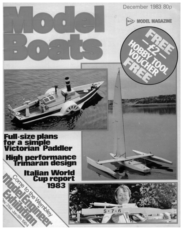
December 1983 80p MODEL MAGAZINE Full-size plans for a simple Victorian Paddler High performance rimaran design Italian World Cup report
THREE TIMES A LADY THREE THVIES A LADY | A 67in. overall high performance | Trimaran by Christopher Stanley. Introduction Regular readers of this magazine will be aware that model 12 metre yachts have been built as a design study exercise in order to help full size yacht designers, by providing information on the effects of design features on performance and handling. This exercise goes under the name ‘Project Acorn.’ The subject of this article is the result of my own, less ambitious, study project undertaken also with a view to full size design. My intention was to combine my hobby with my hope to one day design and build a full size trimaran and thus give myself some design experience and a chance to put theories of behaviour to the test. The resulting model has come up to my expectations in performance and behaviour, is successful as a racing model and a design study, giving me great pleasure and satisfaction on both of these counts. with Description The model is 67in. overall x 60in. water- line length having a beam of 46in. and a design displacement of 11lb. It carries 1250sq.in. of sail. (It fits the 10 Rater rule). A single detachable crossbeam connects the three hulls and carries the deck stepped mast on which is a moderate aspect ratio less work, for a prototype, than moulded glassfibre shells. Handling the assembled and rigged model is made easy by the fact that the central rear edge of the crossbeam makes a convenient handle which is close to the centre of gravity allowing a one handed lift to the water. masthead rig The hulls are round bilged have long runs up to the transom with little rocker, the main, or centre, hull being flatter in section than the outer hulls, or floats. The main hull has only short overhangs as little heeling is present when sailing. a The improved fin, efficiency, forward and a carried with for is tip fence positioned for well relatively large rudder is good manoeuvrability. The rudder is round tipped and inclined forward as this improves its effectiveness at high angles of incidence and when stalled (so the theory goes). No ballast is carried other than two channel radio and a sail winch system, access to this being through a large hatch aft of the crossbeam. The winch is fitted with a system, described later, to ease the sail sheets should too great an angle of heel occur and to reset them as they were when normal angles of heel return. This sounds ponderous but the system activates and resets quickly and effectively, and allows the model to cope well with strong, gusty conditions. The winch is designed to be used for sail leech tension control, for control of sail twist, in conjunction with sheet horses and so is very powerful when compared to the typical servo based winches now common. The bulk of the model’s construction is of balsa/glassfibre sandwich as this method produces a light and very stiff structure 636 Design philosophy Builders may find a few words of the principles of design enlightening, if not interesting, and helpful in understanding their model. The principles involved are the same as those used in monohulled yacht design but are modified and extended to allow for the effects of less heeling and more hulls. As you will see, the configuration of a trimaran can be used to advantage. Heeling stability The basic mechanism providing the yacht’s righting moment is easily under- stood, this being the buoyancy of the float as it is depressed into the water acting at a large arm from the yacht’s centre of gravity. Since the sum of downward forces must equal the sum ofthe upward forces, then as the upward force from the float’s buoyancy increases, the main hull displacement must reduce, i.e. it lifts out of the water. As Fig. 1 shows there is a third vertical force involved. This is a component of the heeling ing its float completely, without causing the main hull to leave the water but does not generate as large a righting moment as it might. Of concern to the full size designer is that this type can, and does, immerse its float and trips over it when thrown on its beam ends by a wave, even under bare poles. The third type, where B is much greater than W is not capable of immersing its float by either sail and/or wave action so it will lift its main hull from the water and tend to Fcos & F sine force F, Fsin6. The values that the designer gives these three forces, i.e. the yacht’s weight W, float buoyancy B and sail down force Fsin@, determine the behaviour of the yacht at and beyond the limit of its stability. There are three basic design types in this respect. These are: where B is less than W, greater than W and much greater than W. The first type will be capable of immers- wo with fine reflexed waterlines at the bows, Model Boats
pivot over about the float. The onset of hull ‘lifting is not readily observable from on > board and can occur and continue very IN rapidly due to combined wind and wave action and has also led to lost craft. F cos @(Thru CE) = As you will have guessed, my choice is the second type whereB SS| is greater than W. GE More accurately, where B is a little /ess than the sum of W and F sin@. This subtlety Thrust gives several benefits. It means the yacht ——— u F sine can immerse its float by sail action and so Thrust | will lie down in a gust, but the yacht’s weight alone will not immerse it and so the F cos @(Thru CLR) — eae ee Drag main hull will not leave the water. Float immersion under sail happens relatively slowly, hence controllably. It allows the Fig. 2 righting moment to be safely maximised also. One can see from this that for this type of trimaran, maximum stability is a function = a Fig. 3 eras | ot.— | wy 8 produced by the thrust and drag forces can of gravity, having made allowance for the of the values of F, B, 8, beam and design sail down force F sin 6, such that this bow weight W but is not improved by exceeding depressing moment is equalised anda the design weight. This fact makes it very trim preserved, see Fig. 2. resistance CLR (the point through which Yaw stability rudder is considered to act). See Fig. 3. As in a monohull the centre of effort of the rig CE (the point through which resultant force is considered to act) moves result in a yacht which is well balanced be counteracted by placing the CE a suitable distance from the centre of lateral level the combined lift forces of the fin and important that the model is built to the design weight to ensure maximum performance. Pitch stability In any yacht a moment is produced by the thrust and drag forces which Applying these principles with care will over its whole stability range and be well behaved in gusty conditions. outboard with increasing heel, but to a lesser extent as there is less heel. With increasing heel the drag on the float tends to depress the bow. Ina trimaran the centre of buoyancy of the float is positioned a suit- Full size plans for Three Times a Lady are available from Mode! Boats Plans Service, PO Box 35, Wolsey House, Wolsey Road, Hemel Hempstead, Herts. HP2 4SS. Sheet one is shown below. sheet two includes details of centre wing and hull shadows. Price is £4.85 plus 50p post and packing. increases so a ‘centre of drag’ also moves outboard from the centre. The moment able distance forward of the yacht’s centre Sheet = (D 1of 2 designed by 1/B°PLY KING C.Stanley PLANK AS WEIGHT The MODEL BOATS plans service HULL PO Box 35, Wolsey Road, Hemel Hempstead, Herts. WITH FITTINGS RIG Mb 10; > et EACH ~ NOTCH INTO PLY DECK aR sa roe AB” PLY DECK BEAMS aS i 41, Oor FLOATS FOR JIB FITTING AS sone BREAKDOWN BEAM 3/8* sar HARDWOOD BEAMS AS REQUIRED REQUIRED — _ Wa PLY STEM (Toft) RADIO, WINCH & BATT _2ip Sex ETC 1ib — 67* LENGTH OA. TAKE DRAUGHT IF – 12-4* DISPLACEMENT – GREAT CARE NOT = Ooz 1/4°PLY eeees NECESSARY ce | TRUE } / / | oa SS ee DECK LEVEL eg < 1 = | : —— | = — ee =— a =. “HS | a ae aD | | St | Ca Fioat Set seer T —- sp ee [eons‘SPACING INTERNALLY WITH On REMOVING CLOTH TIP FENCE | / } | | B% KC at 50% C DECK LEVEL toz sar yd GLASS SHADOWS 2 to) CLOTH TISSUE ALTERNATIVELY TO j i | H FIN CASE sioes (20H) H USE oz sar yo \ | i =| | i » STEM SPACERS (20m) | | j vee | i / / = | FROM ———_——_ —— \ ‘ AREA (CM SOR 644 2.08 sores / RUDDER = ree 2 i 2 DOUBLER —— f | AROWOOD ; — ot SOmC THICKNESS WITH GLASS FIBRE TISSUE \ SS Wa ee iY | STN | é~ : | | STEM | — | ween” a“ } 4+—1/4"PLY OR ' | | { PLANKING \ BALSA SHAPE & SHEATH \ EXT & INT |_eoins pawn partum AXIS eee, LAMINATE CLOTH AFTER |} a A 1/8" BALSA STRIP 2 | } \ \ Boz sar yd GLASS ay \ FIN eensLAMINATION \ WITH Dd V8" BALSA SHAPE & SHEATH WITH GLASS FIBRE TISSUE \ (Nera ; j | 1S% KC SHEATH HULL EXTERNALLY cLe LAMINATE UP TO 1/2* WiTH \ ig / 6 SIZE ee TENING Va PLY \ CHAMFER TO THIS LINE ~ T { 1/2FULL | \ ro | Tr 4 jt 3 a =] } PLAN & ELEVATION DRAWN HOLE \ eI s ~ Hh ee — r I {v DRILL A NUMBER o DECK STRINGERS — ( ~ NOTCH TO LOCATE DOUBLER (2oft) vet = SE neeai ZJ ve" BALSA | wel. Ee 2 [ a: | (ioft ) BALLAST STATED 1tilbs SAIL AREA — 1,250.sqr_ins | BREASTHOOK ‘ibs ALL BALSA MEDIUM UNLESS’ ©OMERWISE 60° [Goesousun LWwe 70 ifiiseres | SHADOW 6. oe Te | aSsSemace with = | | ~~ BOWELS | [= ——__— Peat | FINSHED DECK [Pr=| (VB BALSA) — INOR SPRUCE STRINGER WA6*PLY LOCAL DOUBLERS FOR BACKSTAY FITTINGS = waTcH COMMING & HATCH coves 1/16"PLY OR LESS TRANSOM Ly COVER eae dimection iD reat ite GLASS CLOTH MM/1355 December 1983 637
outside, then inside. The shadows were For anyone interested in learning more of the principles of yacht design | thoroughly recommend reading Aero - Hydrodynamics of Sailing and Sailing Theory and Practice by C. A. Marchaj (Adlard Coles Ltd). made up as shown in Fig. 4 from pieces of y,in. balsa, slotted for stringers and glued to %,in. square timber which was then screwed to a suitably marked out building Mark board. All stations are temporary except one and the transom so these should be of good medium balsa. Add the in. ply stem Construction Before describing the method of construction, some thought on related aspects. As mentioned above, to obtain best per- formance the model should not be made overweight as this will be of no benefit, but nor should it be underweight. To ensure the target weight can be reached the builder should employ weight control and keep watch on weight as construction proceeds. Below is a table showing the weights of components of the prototype model which can be used as a guide. Individuals always have preferences as to how and with what to fit out their model and thus the installed weight of radio, winch, battery, etc. will differ from that in the table. Ib 4 1 1 1 Fig. 4 | would recommend that your first step be to gather together a// the hardware to be used in the model, including fittings, screws, tubing and pins, etc. and weigh it. This will allow appropriate target weights for the hulls and beam to be established, after allowing for any changes. Construction can then begin. Table 1 Hull Beam Float Winch and radio Battery Rig and fittings and deck plate and the balsa station one to oz i (@) 2 each 11 10 12 Hull The grp/balsa sandwich is produced by first making the hull shape by strip planking over shadows in the conventional manner using balsa then sheating it with grp, first the board as a ready glued assembly with the stem balsa laminations already applied to both sides. Glue in first the keel stringer then the deck stringers and when dry chamfer as required the stations, stem and deck plate so that the planking will lie fairly. Mark on each station the extent of its straight edge and transfer these marks and the stem notch position to a sheet of \in. balsa by temporarily pinning it to the structure, ensuring that it fully covers the deck stringer. Two sheet lengths are needed for each hull side which can be _ butted together. Draw a line through these marks and cut along the line, making it smooth with a balsa plane. Use the pieces made for for making one side of the hull as templates those for the other side, and glue the resulting four pieces back in place using pins to hold them. The remainder of the hull is strip planked using 1,in.-%in. wide strips according to the curvature of the hull. For economy, strips can be cut from sheet using purpose Finish made tools available at your model shop. Using a less powerful winch than that described below may also mean that a Use straight grained wood. Plank from the bow by cutting an end of a strip to a wedge shape to fit between the stem doublers and the skin sheets or previous plank. Glue and different sheeting system and mast step method may be chosen. Any such changes should be carefully considered early and the resulting weight difference taken into pin it in place working aft and complete that plank with a second piece of the same width butted to the first over a station. Apply planks in this way to each side alter- account. For a keel stepped mast additional hull frames of ‘U’ shape will be needed plus deck slot and reinforcing. Also the crossbeam would need to be slotted and reinforced. Alternative jib fittings would require natively. This may not produce the most elegant planking but it will serve its purpose. When complete, the joint between the skins at the bow can be tidied up by cutting them back to form a flat and suitable deck beams etc. Should the builder adopt moulded grp construction then the laminate thickness required should be predetermined. Weight allowance should also be made for suitable finish, whether it is to gluing and pinning in place a cap strip of hard balsa or light hardwood. The hull can now be sanded to a smooth shape. Use coarse then medium grade paper and a sanding block with little pressure otherwise the balsa will become thinner at the stations and produce undulations in the shape. Shape the stem and bow cap to the lines of the hull to produce a blade like bow below the waterline which should not be be paint, pigment or gel coat. made less than ¥,in. thick at its edge or it will become fragile. Use the lamination of the ply stem as a guide to the correct shape and to show shape differences between the Above: low angle view on bow after shaping and before sheathing. Right: completed main hull planking showing stem doublers before shaping. Left: detail of bow construction showing skins strip planking, stem doublers and cap strip before shaping. Note shadows. Above left: completed main hull planking. 638 two sides. Sheathing Now comes the messy bit. How you tackle sheathing the hull will depend on your experience with glassfibre. For the record, my experience was virtually nil. In order to provide a strong yet light sheath with a good surface the prototype was sheathed with a single piece of glass c/oth, chosen because cloth requires less resin to Model Boats
saturate it than does matt for the same Decking Fig. 5 thickness and provides more strength. The The hull is now ready for decking with Ygin. balsa, grain athwartships for economy intention was to similarly cover with finishing tissue cloth while the resin was wet to soak up any excess and improve and the extra stiffness it gives. Cut all the pieces required and use resin to paint all the surface, but this proved easier said than done so it was omitted. The cloth used was surfaces of the deck beams, fin case, etc. and the underside of each piece of decking 80z/sq.yd. and the tissue 10z/sq.yd. The cloth proved to be on the heavy side although it made a very strong and stiff hull. This meant that to avoid being overweight the inside of the hull was sheathed only with the tissue cloth which seems sufficient. A better result would have been achieved using 40z cloth both outside and inside without being any heavier. When calculating weight of layup use thus gluing them down. When cured trim up and structure to carry the jib fitting loads. As indicated before, what form this takes will depend upon the type of fitting to be used. That shown on the plan is for the jib fitting shown in the photographs, but can be simplified for other types of fittings. Take a little trouble to make it light yet efficient the hull in one piece leaving a few inches such overlap all round with a slit at the stem to hardwood resin (use epoxy resin if you can come by it) by applying with a brush and spreading it out with one of the special segmented washer type rollers available from grp material suppliers. Be very careful to apply only enough resin to just wet out the cloth, otherwise too much weight can easily be added. It can be removed partially by dab- as thin plywood edge beam webs with reinforcing to accept screws. Make a drawing or some record of the method you use so that you know where to find it when covered by the deck! Next to be added is the fin case. Assemble the cheeks and spacers as shown on the plan and prepare to make a slot in the hull bottom to accept it. Measuring from station 1 mark out the required slot on the inside of the hull and cut it down to the exterior glass bing with scrap cloth. When fully wetted fibre but not through it and place the case out apply finishing tissue cloth if you wish. into the slot. Make up the %in. square deck beams with central slots to accept the case If necessary apply a little more resin to give a uniform appearance and surface finish with no white coat visible. In order to make sure of a neat bow by excluding air from between the hull and cloth at that point apply a shaped piece of wood as shown in Fig. 5 to each side of the overhanging cloth and hold them in position by clamping with clothes pegs. When the resin has properly cured, normally a few days at room temperature, longer if the temperature is lower, the hull can be removed from the building board and tidied up. Make three temporary deck beams from lin. x in. timber and screw these firmly across the hull into the deck stringers, then knock out the shadows and keel. Smooth the interior surface as before and slightly round the stringer lower edge. Cut a piece or pieces of your chosencloth to apply as the inner layer of the sandwich. Wet out sparingly as before and ensure that the cloth is properly tucked into the corner under the deck stringer and neatly folded onto the transom. Cut darts here as required and apply a piece of cloth tissue to the transom. If using tissue only, add a 2-3 inch wide strip along the length of the keel. When this cures the excess cloth can again be trimmed and then plane the deck stringers to provide a flat surface to which the deck can be applied. Remove one or two of the three temporary deck beams as required to make this job easier. Internal structures The next stage is to add the required structure inside the hull. Working aft from December 1983 the deck edge and sand tissue (if your weight build can stand it use the bow the first item to be added is the 3.50z/sq.ft./mm_ thick finished. Sorry about the mixed units! Cut your chosen glass cloth to drape over improve its lie here. Begin wetting with round smooth. Sheath the deck with one layer of and centralise it. Notice that the case protrudes gin. above the deck beams and will become flush with the deck when it is applied. Use resin to glue the case and beams in place and when cured cut the slot two layers or a single layer of 20z cloth) draping it over the hull by 1, to 1in. Also cover the hatch coaming with tissue to make it more abrasion resistant. While you are busy with cloth and resin add a small wrap over doubler to the bow for additional strength. All that remains to be added to complete the hull is the rudder tube, preferably stain- less, and the rudder pushrod exit to choice and the sheet exit. The hatch cover is from ¥gin. balsa and is simply painted with resin, sanding sealer or similar according to your finishing requirements. Crossbeam This part of the yacht is the most severely loaded and has been carefully designed to do its job and yet be light and stiff. To achieve these requirements it is necessarily a more complex structure. It is built like an aircraft wing in that it has spars and ribs and has a similar sectional shape but is inverted. Construction begins by pinning the drawing down onto a board as it is used to position the structural parts. Make up the in the hull sheathing to accept the fin. If you intend to keel step the mast then two spars as shown on the plan and cut the add two ‘U’ shaped plywood frames 3in. or SO apart and a piece of hardwood along the keel between them. Also use resin to glue from 4in. balsa). Make the beam end ribs doubler blocks to the deck stringers, to take the beam fittings, the balsa deck beams remaining, the hatch surrounds anda small ply doubler on the centre of the inside of the transom. Below: crossbeam structure on building board. central rib pieces. (If you intend to keel step the mast then make two such sets of parts and pin them in place on the drawing with the two spars glued between them into the notches. Glue the pieces of the central rib in place, and then the remaining pieces can be added to this framework beginning with the short spars and their end ribs, then the remaining ribs. These rectangular pieces can be cut in pairs to the required size and glued in member place. oversize Cut and the the leading edge trailing edge member to size and glue them in place. Then add the remaining pieces of the ribs as rectangles which then are shaped, with the leading edge, using a straight edge from beam tip to centre rib, to show high spots. Carve and/or sand them till the straight edge shows contact at each rib over their length. Reinforce the junction of each rib and spar by adding a piece of in. square balsa. The structure should now look as in the photo and is ready for skinning. Skin with 3in. sheet between the spars first then the remainder, using pins again. When well dry remove the whole from the board and trim up. If you wish, the interior surfaces of the beam can be given a single coat of thinned sanding sealer. Now similarly apply skins to 639
the other side of the beam and again trim up and add the leading edge capping. Carve and sand it to give a good rounded shape as shown on the plan. The last pieces to be added before glass sheathing are the end bars. These can be from ply or hardwood should be cut much overlength to and provide handles with which to hold and support the beam during sheathing. Mark on the underside of the beam the positions of the hull and float attachment members. Apply the glass cloth sheath with the same care as before, ensuring minimum resin usage, using 80z/sq.yd. cloth, preferably in one piece by wrapping it round the beam as shown in Fig. 6. Ensure that the warp of the cloth is along the beam and that it covers the full extent of the top and bottom of the beam. Fig. 6 — aT ins GED) Se lve Trim off excess cloth when cured and cut off the beam end overhangs flush with the leading and trailing edges. The beam should be kept flat for some time until the resin has cured fully. Make up the hull and float attachment members and check them for fit to the beam using the marked lines for guidance. Adjust as necessary to ensure a Close fit, that the central ones lie parallel and flat and that the end ones lie at the correct angle and parallel to the beam end. Use dowels to position them accurately and use resin to glue them in position. Add the remaining pieces of ply and balsa as shown, using resin as glue and paint. Holes for assembly pins will be drilled in these members later. Floats The floats are made by the same method of construction as the main hull and in order to speed up construction they should be made simultaneously side by side on the building board. As an economy measure make the float shadows in pairs using the material used for the hull shadows. Build just as the hull and sheath with two layers of 10z tissue cloth, again in one piece, and when removed from the building board all stations except 1, 5, 6 and the transom are removed and one layer of tissue cloth applied internally. Hardwood blocks to accept the float attachment fittings are set into the deck stringers forward of station 5 and aft of station 6 to be flush with the finished deck, i.e. Yin. proud of the deck stringers. The deck is applied and sheathed as on the main hull. Lastly add the spray deflectors. Fin The fin is a laminate of 4 in. ply and balsa sheathed in tissue, which slots upwards into the hull, Ensure that the plywood centre lamina- 640 tion is cut from unwarped sheet. Make it up to the required thickness with balsa laminations and shape to the section shown and to fit up to the hull leaving minimum gap. The section is a low drag gear ration of 60:1 driving a conical drum supported in a bearing. The conical drum gives rapid sheet movement when well off and lightly loaded, becoming eased its slower as they wind in and loads increase, giving finer adjustment when fully sheeted Sheath with cloth or tissue to give a hard approximately three seconds. To avoid the turns on the drum slipping to the small moderate thickness shape having maximum thickness at 50 per cent chord and a well rounded leading edge. and smooth surface and add the plywood fence to the tip. Paint the remaining wood surfaces with resin or varnish. Ensure that the tongue to be inserted into the hull does not become too thick making it a tight fit. It in and greatest pull. Full sheet travel takes diameter end a piece of cord is glued to the drum surface in a spiral of the required number of turns; see photo. should slide easily in and out. Rudder The rudder is two or more laminations of with the shaft glued between on balsa assembly. It is shaped to a thicker version of the fin section and sheathed as the fin. Finish Now that all the parts have been made they can be prepared for the finish of your choice by using wet emery paper in various grades to improve the surfaces. Any blemishes that appear as this work progresses Even can be filled with plastic fillers. if the weave of the glass cloth is evident at the outset as a rippled surface a good finish can still be achieved with patience and effort. This is where care at the sheathing stage will pay off. The prototype was painted but if choosing again | would use gel coat in the desired colour. This can be either sprayed or painted on with a fine haired brush and polished up to a good gloss. | have learned that it is very Winch drum with helical rope guide bearing mount and shaft extension for feedback cord. The proportional control comes from switchgear based on a design published in Model Boats some years ago. A servo driven circle segment with two cam faces operates two switches which wind or in normally make wind out closed the winch according micro- either to the easy to add too much weight at this stage, direction in which the cam was moved and hence which switch was opened. Winch segment underlying the first and on the same pivot. A cord wrapped round a small so be sparing with your finish. The winch in the prototype is unusual in that it is so much more powerful than most winches in use today which are based on servos or are enlarged versions of servos. The reason for keeping the weight of these winches, hence their power, low is to maximise the ballast ratio of the monohulls they are used in. There is no such require- ment in a trimaran and hence a generous proportion of the all up weight can be used for the winch system. (If designed for servo type winches the yacht could have been lighter, perhaps by 1lb, but a 10Ib yacht with 1250sq.in. of sail would carry very little way in a wind). The winch power sub- sequently available can be put to good use with sheet horses to pull downwards on the boom ends, thus controlling their height and hence sail twist. This is a more effec- tive method than relying ona kicking strap which tends to bend the mast at its lower end and cause poor sail shape. Also the mast can be simply deck stepped. A kicking Strap is fitted but is only effective when the sheets are eased and the rig is less heavily loaded. To provide the required sheet tension the winch uses a monoperm pile unit with a The switches are mounted on a similar diameter shaft extension of the winch drum and fixed to the lower segment causes this segment to move about its pivot, either pulled towards the winch by the cord or away by a return spring or elastic, according to the direction of rotation of the winch. Its operation is as follows. Servo movement of the top segment opens a switch causing the winch to run. The lower segment moves by action of the cord in the same direction as the top one until the switch is again closed and the winch stops. Hence the winch rotation is proportional to the servo movement. The switches are wired so that the motor is short-circuited when both switches are in their normally closed positions and so rotation is rapidly stopped when the desired position is reached. All of this could be replaced by an electronic servo amplifier and it is my intention to do so when | can come across a design capable of handling 20 watts. As mentioned before, a safety device is fitted to the winch which causes it to ease the sheets should a large angle of heel occur. This consists of two mercury tilt switches and a double pole, double throw Model Boats
on/off Fuse/cut out Fuse/cut out ‘in' over run cut out Fig. 7 DP DT oa) eT RE ici eeteee: WS. relay ThGomer Now, ot ean Se Fig. 8 PNT ee DPDT relay er ee ee ‘out! over run cut out of on/off Winch in N 2 BK: T Amplifier ps, hs NC = C - Common NO = Normally Port tilt switch / open Stbd NC - Normally tilt switch = L asad tilt switch % Stbd tilt switch nor 1 ov dia. stainless tube which projects both for- a securely fixed to the hull floor in such a mercury switch closes at approximately position as to make the C of G of the ward and aft of the mast so that the forestay 45° of heel the relay is energised. This makes another circuit which by-passes the winch control switches completely and assembled yacht lie at the correct position. and backstay loads produce no bending in A the mast. (DPDT) relay wired such that when makes the motor run so as to ease the sheets. This quickly reduces the angle of heel until the mercury switch opens again de-energising the relay. The winch control switches are now connected again and due to the above winch rotation the ‘winch in’ switch will be in its normally open position causing the winch to run until the pulley is fixed to the deck stringer opposite the drum to turn the sheet forward to the deck exit under the beam and from there to a bow turning pulley then aft to respective sheet horses. Rig and fittings Some fittings on this model differ from common practice and are described below. The masthead carries a jumper of 6mm Both kicking straps are fixed to the booms fairly close to the goosenecks so the loads they apply have their greater part vertical. This again reduces mast bending effects. Control of the sail foot camber is provided by a cord and bowsie arrangement along the boom rather than a fitting with several fixed positions. The four bottlescrews on the main and inner shrouds need only be of 6BA threads with minimum body diameter to keep their mechanism resets to the position it was in at the start. A study of the photograph should make things clear. The complete circuit is shown in Fig. 7. combined weight low. Drilled aluminium plates screwed to the beam end bars and transom If you wish to use an electronically con- provide shroud and_ backstay trolled winch you should still use the above attachments. Ensure that the bottlescrews safety device by following the circuit shown in Fig. 8. are captively fitted to these plates as the When choosing your winch make sure that it can cope with the greater rig loads experienced on a trimaran. Use one which when the yacht is sailed hard. The shrouds leeward shrouds can become quite slack themselves can be of light wire, such as 40- Continued on page 666 can provide about 30 per cent more pull, preferably 50 per cent, than one you might use on a monohull with this sail area. Additional safety devices fitted to the prototype’s winch are over-run switches and a fuse. The whole of the winch and radio system is mounted on a stiff base plate which is Top: view looking forward on port float to beam attachments. Float deck in foreground. Above: main clew outhaul. Right: mast, step etc., jib horse etc. Left: view through hatch into hull showing motor gearbox and drum, upper right, radio box and servos, upper left, battery, lower left, switchgear, lower left and safety relay centre. December 1983 641
NOUN tne GA WAS !1YRU European Radio Marblehead Championships The first event for this title was run by the Swedish national authority at a large lake 30km north of Stockholm during August. A very well organised event, comprising five days sailing with one break for a scenic trip by boat from Stockholm gave all the 27 entries plenty of time on the water. The hosts were very surprised by the lack of entries from the UK, with only Graham Bantock Norman Hatfield down to sail, further reduced when the latter had his boat and equip- and ment stolen in Oslo en route to the event. This lack of entries allowed two expatriates from Hong Kong, Richard Eastwood and Peter Wood, to enter sailing American designs, Bone and Spot. Both were somewhat lacking in match practice in the predominantly strong winds experienced during the whole week, as were the Italians and Swiss. All the Italian boats suffered structural failure on the first two days and were withdrawn before your reporter arrived at the lake. Sailing conditions were made more difficult for all the visitors by the substantial waves that built up over the mile width of the lake with a moderate on-shore breeze blowing, and it was clear that the Scandinavian boats were rigged with lower- aspect ratio sailplans to cope with the swell. The winning and second place boats are well known already to readers, but in third place came the young Dutch 16 year old Jan Mooijam, sailing an unusual boat of his own design. The hull hada a marked chine on the point of maximum beam with the sides above showing substantial tumblehome. Two-part GRP moulds are used to form the hull-shape. Fifth place boat was a very attractive Swedish boat designed by a local dinghy sailor which had sections showing the same basic idea as the Dutch boat. This boat was generally regarded as one of the most attractive present, in contrast to the almost dart shape of the Bellander boats of which several examples were sailing. The event was conducted with efficiency by OOD Jan Dejmo and his team and enjoyed by the competitors. Chris Jackson Results Total of 22 sails, 4 discards Pos. Name Nat. Points 1 T. Klem NOR Se 7 2 S. Andresen NOR 49.6 3 J. Mooijan HOL 68.4 4 C. Fagergren SWE 70.4 5 L. Andren SWE 73.4 6 P. Tailliez FRA 115.4 G. Bantock GBR 286 17 Frenchman Patrick Taillier’s Masque Concombre RM followed by Dutchman Jan Mooijman's o/d RM at the European Championships held in Sweden. Photo: Chris Jackson. few new boats, but to designs that had been seen before. The weather was very kind, a good wind, giving some variety in direction and strength to test the rain, and Fleetwood organised a variety of social events to get families together. From the start it became obvious that Chris Dicks was very keen to win with Revolution for possibly the last time, that Mick Harris felt the same about his first race with Supertramp, and that some Lo/lipops would do very well. For most of the week Revolution and Kialoa fought out the top two places, the winning beat occurring in the last heat of the championship. Perhaps Chris had that extra bit of determination. The two black Stollery designed Lo/lipops came next, and then Graham Bantock’s design, Supertramp, very well sailed to windward by Mick Harris, but failing somewhat on the runs. Alex Austin again sailed That into the prizes, and sixth place was taken by newcomer to the prizes, but not to the Champion- ships, George Clark, with S/o-Mo-Shun, a Butler/ Sykes Sulara design (the same as Sundance). Another newcomer to the prizes was Chris Jackson, sailing a Stollery design, Rolling Stone. It was interesting to see how High/ander performed after all these years — 1961 was the last time Dick Priest won the championship with this yacht. | think all agreed that the boat was outclassed by modern designs, but it could still win downwind, and did not disgrace owner Dick Priest, or the two crew who sailed the boat. There were many more younger people in- volved in sailing than last year, a good sign for vane sailing — many have been introduced to it by their fathers, and they seem to get smaller. There were one or two problems on the first couple of days when small arms had difficulty turning an A boat with a pole when the boat came in at an awkward angle, but as the week progressed there was not a lot of poling to be done on the mate’s bank, long legs and guying gave the skippers most a number of past holders of the trophy amongst the 40 entries. These included Chris Dicks, Dave Latham, Mick Harris, Roger Stollery, Alex Austin, and the welcome return of Dick Priest. There were 19 designs, but only one new one, Northern Dancer, designed by Dave Hollom. There were a December 1983 well sailed, in a friendly but com- Joyce Roberts skill of skipper over boat. There was very little work. A Class Championship — Fleetwood — July 30-August 5 The 54th A Class Championships saw organised, petitive way. The schedule was completed, and the best skippered boat won. The International was a four boat race, sailed on Wednesday evening. This race was possibly started a bit late in the evening — it was dark when the final board took place, anda tie resulted between England (K/a/oa) and South Africa. The sail off took place next day, Dave Latham taking the deciding run.|t is a pity there are not more European countries sailing vane A class yachts. All competitors and officials agreed that it had been a most. successful championship, well Cygnets Scale Regatta — July 17 — Mote Park, Maidstone, Kent This event was held on a glorious, sunny day. Our guest judges for the day were Mr. Peter Mitchel of Medway Harbour Board and Mr. Ken Tierney of Medway River Users. The course was a typical Cygnets course with islands, wreck, canal ways and an ‘L’ shaped dock. With 80 entries including tug towing it was ‘sleeves up’ all day for Cygnet members. Full credit should be given to all judges including course judges for keeping up with static, stand-off and course scores. The wind wasa little troublesome on the course and played havoc with some entries but in spite of all obstacles everyone enjoyed the day. With the Scale Regatta completed around 4.30pm, the tug towing event followed, with some very good towing by competitors through the buoys. It was decided to run the event seriously, not as a novelty which made the course easy; thus the six minutes allocated was ample time. Dave Metcalf and Dave Abbott pipped I. Sykes and J. Appleton by two points to win the event. Trophies were presented by the judges. Results Scale 1st A. Lock Stormlight 2nd D. Abbott 3rd A. Lock Tod Head 137pts. 133pts Hibernia 127pts Non-Kit 1st K. Edmeades Fverard 2nd D. Hutchinson 131pts Lynn (Tug) 3rd D. Bayley 130pts TID 126pts Kit Class 1st |. Winchester Paloma 2nd G. Stocking 136pts Inga IV 3rd G. Sheppard 135pts Custom Launch 133pts Pilot Boat 126pts Best Junior P. Harman Tug Towing D. Metcalf D. Abbott Happy Hunter93pts 15 min. 8 sec. Bajima George Baker 651
(leading edge) would be folded into a luff tape, made from linen tape and sewn; the foot might also be folded in, or a straight STARTING IN SAILIN tape sewn across and the roach of the foot hemmed. The leach would be hemmed with as fine a hem as possible, and it was essential (it still is) that the leach be parallel Vic Smeed takes a look at sail materials and construction methods to the selvedge of the material. In any other direction the cloth will stretch and the leach will sag or ‘dog-leg,’ which is why tapes are fitted to the other edges. Hems are not normally used with hot rolled nylon, the material being cut with a hot, sharpish blade which melts its way SAIL works in two ways, as an aerofoil through the fibres and fuses the melted Nylon cure-all ends together in a fine bead. A luff tape is when sailing towards or across the Strangely, it took some years before full- used, but to ensure compatibility this is wind and as a simple ‘bag of wind’ when off size yachtsmen caught up, but when they often a strip cut from the sailcloth (along the wind. Now, an aerofoil works because did so it was with nylon, processed after the selvedge line) with the hot blade. The weaving by hot rolling. This softens the cutter can be an electric soldering iron with shape or section causing a drop in pressure woven strands and squeezes them flat, on one side and a slight rise on the other. the bit sharpened, or a thus filling the minute interstices in the knife can be used, heated ina gas flame and The reason for the pressure differential is weave but allowing the cloth to remain reheated periodically during the cutting. A that air has to speed up around the convex reasonably this thick card or even a hardboard template can became available in a range of be used, or a spring steel wire or wooden of pressure differences on its two sides, the side in order to reach the trailing edge material soft and flexible. Once heavy cobbler’s (leach or leech) at the same time as the air light weights (often used for full size spin- spline pinned securely in place. Some form on nakers) model yachtsmen found it a better of guide is essential to get an absolutely the opposite side, and when a fluid speeds up, there is a reduction in pressure. You can look up Bernoulli's law in any dynamics book if you want to go deeper into and easier material to use and virtually all smooth cut, especially if it is necessary to fore and aft sails are now made from it. reheat the blade halfway through the cut. It it! Note “fore and aft sails.’ Spinnakers, is not unusual to pencil the shape of the sail used by all vane boats, vary in shape and on the cloth but freehand cutting is not size to suit wind strength and angle (a boat advisable. The cloth should be taped flat on may have six or seven in its gear) and one of a clean smooth surface such as a sheet of the biggest problems always was finding an hardboard. It is obviously a bad thing if air can leak through the sail from the high to the low pressure, so the sail material needs to be airproof. It is also easy to understand that downwind a sail made of netting, or thin porous material, will let air through and will not therefore produce as much drive as it would if made from airproof material. This is one reason why a lot of home-made sails provide disappointing results, as however close the weave may appear on that piece of cotton or nylon or whatever from the materials counter or market stall, it is very unlikely to be adequately airproof. Airproofing Airproofing low wind strengths. The various thicknesses are widely used for First time sailmaking Anyone tackling a suit of sails for the first time should obtain the cloth — model sail- balloon spinnakers. Some unrolled nylon is makers can supply it by the metre, and will used for brisker winds, and hot-rolled nylon send you is explain what the boat is etc. — tape it out employed quartering for heavy-weather spinnakers. The flat or use of plain weave nylon may seem strange, since it and the appropriate weight if you mark out the sails, tape strips etc. which will indicate which bits of cloth will ‘leaks,’ but it was found that a degree of air be flowing through a spinnaker stabilises it. tablings Totally airproof spinnakers are often seen possibly batten pockets, but there will be spare. Some will (corner be needed for the reinforcements) and with a central row of holes to allow part of some which can be used to practise cutting and sewing. involved flexible Egyptian material. coating film, common the was the treatments sails with banana choice. cotton) Most of very the air to pass through. Without these the (actually subject in advent of polythene sheet solved this and ex- standard the drive perimentation for many years when Union Silk was airproof material sufficiently light to filland oil being There were appeared impregnated with ‘secret in the varnished synthetic resin, marine cables, or so it was generally under- crack if creased; it also rattled in the wind and was not the easiest of materials to work with, requiring adjustments to sailmaking was, however, infinitely superior to cotton as a sail material and over the next twelve years just about all seekers of performance changed to it. 660 a majority of model sails belly being given by cutting the luff edge to stood. It was not fully flexible and would It Historically, have been single panels of cloth, shape or a gentle curve but sewing it straight into the designed for insulation wrapping on sub- techniques. to which destabilises the yacht. Terylene sails. This material was synthetic cloth leading collapse and the latter side-to-side bobbing ushered with possibly light. synthetic age occurred in 1951, when D.A. MacMonald former fairly ment could not compensate for poorly cut which the a or poorly made sails. change sides, a formulae’ galore, but of course any treat- The spinnaker may spill air from one or both luff tape. There is perhaps a Compatibility An overlooked point by inexperienced sailmakers is that all materials used in a sail must be compatible or, preferably, as far as possible identical. Use of linen luff tape or thread on synthetic sail material, for example brings which, since the similar amount, problems sail will of will cause shrinkage not shrink a the luff to wrinkle beyond any point where it might be stretched out by rigging tension. Other materials may not perhaps shrink, but may stretch by varying amounts. The use of compatible materials reduces the risk of sails becoming spoiled after a few hours of use. Hems In the days of cotton the luff of the sail little knack in doing this while keeping the sail, tape and thread under equal tension, and some experiment may be needed to determine the degree of curve, where its maximum occurs, whether indeed it is just a plain convexity or an S form or what. The amount of curve is quite small as a rule, something like %-/9in. (or 3-4mm) on a sail 15-16in. along the foot. Panelling Panelled sails have become increasingly common over the last five-six years. By using variations on curved edges to the panels and sewing them together straight, a variety of shapes can be built into sails. Further, the seams will reinforce the sail and help prevent it stretching out of shape. Model Boats
Fig. 1 Leach Spinnaker on outer boat has collapsed and blown over to leeward. Yacht thus half broaching to starboard and will be lucky to get back on course. Other boat needs more drive on main to balance thrust of sails. Luff but it is certainly possible to sail a yacht with them. The film is very tough Battens and waterproof, though there is one snag — once a tear starts it will zip effortlessly right across the film, and a tear will start from However, be warned. A sail cut in one piece, totally flat, is almost certain to give a better result than a poor attempt at a panelled sail (more than one national championship has been won with sails cut flat, as a matter of fact!). So for early attempts at sails, steer clear of panels, which look easier than they are. any tiny hole. Thus sewing is inadvisable and reinforcements must be glued in place; Evo-Stik seems to work provided it is not left soaking in water. To set any eyelets etc. in place calls for a reinforcement patch of a Clew woven material glued firmly in place and allowed to dry before punching for the eyelets, and obviously to avoid shrinkage wrinkles a synthetic material is desirable. It Foot Tack Tabling is quite possible to glue the luff in a folded Draughting film sails Some embryo sailmakers have produced acceptable totally flat sails from Permatrace or similar draughting film. Such sails do not stretch into a conventional sail shape and will never be likely to be as efficient as a properly cut and made suit, Terylene tape for conventional attachment the head may also benefit from a small purposes. A very light rub with very fine length of tape sewn (folded) across for the abrasive to cloud the glossier side of the film provides a better key for the adhesive. attachment of the headboard, since this part of the sail takes a fair amountof strain. For nylon sails, patches of the spare cloth Some people use contact cement to fit can be sewn into the corners for tablings, reinforcement, sewing afterwards, but it using rows of stitching around ‘in. apart; does tend to discolour with age and show through as a yellow stain. Possibly Copydex or a similar latex adhesive could be used but this is only a suggestion and has not been tried in this capacity by the writer. il Fig. 2 'S' bend (exaggerated) in sail luff Folded luff tape Above: flowin ajib, adjusted in this case by moving the bobom/boom pivot post bodily fore and aft. Note tabling on clew but not on tack. Jibstay slack as photographed. Left: stitching on jib clew tabling visible. Main tack uses luff and foot tapes to reinforce eyelet position. December 1983 661
Bending There are various ways of bending a sail to its spars or cords, all of which must provide adjustment to the luff tension and the position of the clew (the bottom aft corner) in order to control the amount of flow in the sail. Both jibs and main luffs should be taut, that of the jib very taut or the yacht will never sail properly. The main luff need not be tensioned quite so hard, particularly in light weather, but it should be taut enough to be free of any suggestion of wrinkles. Flow is the amount of curve allowed in the sail by adjusting foot length. In hard winds the foot can be taut, since it will still set in a curve, being only attached at either end (i.e. the tack and clew corners). In very light winds the clew should be brought well in; if you push your finger horizontally across the boom to poke the centre of the sail foot sideways, the distance between the dog-leg so made in the sail and the centre-line of the boom should be about 20 per cent of the foot dimension. In other words, with, say, a 15in. foot for 3-4mph winds so you should be able to push the centre of the sail foot sideways by about 3in. or even a little more. As the wind freshens the clew is moved out to reduce the flow until back to taut for hard winds. Spinnakers 5‘ One sail which is rarely used except by vane skippers with racing models is the spinnaker. Flying and stowing a spinnaker has been done by radio, but so far without clear advantage in normal racing. However, sport sailers could have a lot of fun with one. It can be hooked to the mast hounds, i.e. where the jib is hooked to the mast or Fig. 3 6- Panel sail can be big enough in light weather to hook to the masthead. If the jib gets in the way it can be removed or the clew unhooked and the sail rolled round its stay. Top edge faintly curved Most class yachts limit the spinnaker boom length which usually works out similar to the main boom. It has a gooseneck type pivoting pin which slips in a plate or tube against the mast and its outer end is suspended by a bowsied line hooked high up the mast; sometimes a line beneath is used to control its angle from the horizontal. Lines from the outboard end lead fore and aft to adjust its radial position Panel and the forward one is frequently sprung by inserting a length of strong elastic. The sail Fig. 4 deta Spinnaker hooks here (or higher) ea a Spinnaker boom on an A class yacht, sheeted well forward so that balloon will tend to lift rather than depress the bow. Spinnaker boom uphaul Main boom must be on starboard side if spinnaker boom is to port a Main boom Sheet for spinnaker clew [7 2 Downhau! Afthaul Spinnaker boom Forehau! Elastic 662 Model Boats
head hooks to the mast, its tack to the spin- Chinaman to the main boom to prevent it snorting downwind run is intriguing and naker boom, and its clew is controlled by a gybing over, or to bring exhilarating and well worth a sport sailer it back smartly line on the opposite side of the yacht. If the should itdoso. A Chinaman is no more than making the boom etc. The sail itself can be boom is changed to the other side, the sail an elasticated line biasing the boom to its from two polythene halves sewn or stuck tack and clew change names! The boom is rigged on the opposide side proper side. together, to the main boom, and some skippers fit a of the sailplan to produce a straight and Getting a spinnaker balanced to the rest or even joined with plastic in- sulation tape, which is also used for corner reinforcement. Try it — it’s great! Number 5 involves amendment to two or three LOGBOOK of the A rules but is basically to cover a situation where a double-luffed jib on a rigid forestay is not allowed to project ahead of the stay, which they tend to do in light winds Model Yachting Association News or in other circumstances when the sail is less than full and drawing. At the meeting officers for the forthcoming year are elected and clubs may put forward nomina- NOTHER club providing details of its water national press, so that some extremely useful tc. is Birmingham MYC, secretary P. Lock, publicity resulted from the event. Presumably the Flat 14, York Road, Erdington, Birmingham B23 next event will again be held at Newport, though 6TE. The club was sailing from before the ‘14-'18 some might feel that Perth would better maintain war at Salford Park pool by Spaghetti Junction the association with the full-size! Motions to be put to the 1983 AGM which will Birmingham MYC, both clubs remaining separate 1939 when the Witton club returned to begin at 11.30, December 3 at Francis House, Francis Street, London (five minutes walk from Salford Park. From 1949, thanks to hard work by Victoria Station) have been circulated to clubs for members and a helpful Parks Department sailing discussion; any amendments must be returned by recommenced at Witton; the Council edged the club lake in, 1950/1 and allowed a Nissen hut to be motions are: used as a boat store. The two clubs merged and sailed for the combined trophies of both. A subcommittee was set up in 1955 to study the 1. secretaries by Constitution October the rule 6(1), 2. Championships — ‘’National Championship Meetings associated with Bournville MBC and the IRCMS. affiliated clubs’’ (Woodspring). 1976. Briefly, — affiliation fee, possibilities of radio and in 1959 the club became No radio racing was, however, recorded until 31. delete ‘‘between the ages of 17-65.”’ shall be open to all members of 3(1) R/C rules — “‘In computing final scores... a yacht’s score shall be the total of the points The fact that a stream runs through the pool has always created problems with silt and debris, scored in all the races she was entitled to sail.”’ (Woodspring, Chippenham, New Forest). but Birmingham Parks Department has now fitted 3(2) 6m — ‘‘The GM endorses the actions taken a grille at the inlet and the silt hump near the inlet by Council on the proposed new rating rules for is dispersed from time to time by members using a 6m class yachts.” silt pump. There is normally a minimum depth of 16in. for vane boats and about 20in. in the area used for R/C. All classes of vane boats are sailed, 4. 36R rules — “The MYA adopt the new Rating Rules/Certificate.”’ 5. Arules — Sections C and D etc., an amend- there is free car parking adjacent to the lake anda ment to tie down more positively the line of the clubhouse fore triangle and prevent projections forward of it. with canteen and boat storage The first one is simply a return to the position facilities. To reach the water from the M6 turn off at Spaghetti Junction (Junction 6), circle the island and leave up Slade Road, to the left of a pub. Pass under railway bridge, turn third left up George Road to the dual carriageway road. Turn right on this and the first left is Gipsy Lane. First right up here is then Faulkner Farm Drive; cross the car park and turn left along the drive past the first pool held up to the 1982 AGM — laudable though the idea of youngsters and pensioners not having to pay an affiliation fee might be, the number affected was perhaps more than anticipated, and a lot of the old hands themselves felt that it was unfair not to contribute the quite small amount involved. Motion 2, one presumes, is perhaps to open the new R36R championship rather than, at club present, barring former national championship members sail are not given, but there is some winners. All other championships are already activity most weekends and Sunday mornings are probably a good bet. An SAE to the secretary open, unless entries reach a level at which the would give precise information. unsatisfactory race. Mini-America’s Cup eliminate discards, about which there has already to the sailing water. Details of when OOD feels that any more would result in a totally Number 3(1) is presumably designed to John Cleave, the first ‘foreigner’ to win this cup been a fair amount of discussion; most people seem either for or agin them in principle, so this at the end of August/beginning of September. may become a hardy annual! 3(2) — not connected, but the secretary nodded off in the numbering (?) — merely gives an opportunity to the right to challenge was John Black’s, and the vacancy of Publications It may also be worth mentioning at this point than October 31 in order that a properly prepared list can be made available by January 1, which is no more than normal practice in most associations. September Council meeting Matters arising from the May minutes included reports that the Eric Nuttall Award would be ready for presentation at the AGM, that the water level at the London Docks will be far too low and access too limited for model yacht racing and other matters not yet brought to conclusion. The pro- posed new League points system details were delayed in the post and a sub-committee was therefore established with freedom to deal with the matter. The Hon. Treasurer’s report was encouraging and no increase in subscriptions is necessary. From an item later in the meeting it appears that there is every likelihood of third party insurance acceptable to local authorities being introduced for all members at no cost to them, a very worthwhile benefit of membership. National Championships for 1984 were finalised (note that there are some alterations to the provisional list) as follows: Closing date AClass Gosport M Class Fleetwood July 28-Aug. 3 June 16 May 5-7 April 7 June 30/July 1 June 2 10r Class MYSA 6m Class Sept. 22/23 Aug. 25 Birmingham 36r Class Clapham Mar. 31/Apr. 1 March 3 Little Sept. 2 Aug. 18 New Forest May 26-28 April 28 Hove and June 9/10 May 19 Fleetwood Portugal Radio Classes RM R10R Brighton at Newport, Rhode Island, went back to defend it Top boat of the dozen US contenders sailing for for Secretary. List must be received by the Hon. Sec. not later The MYA AGM leaving those behind to reform as the Salford Park until Notice in November). Nomination(s) will in fact be essential that fixtures to be included in the 1984 Fixture until 1933, when the majority moved to Witton Lake and formed the City of Birmingham MYC, tions (a form will be issued with the formal GM RA Chelmsford June 23/24 May 26 R36R Guildford Sept. 15/16 Aug. 18 Others Champions Cup Leicester Model Maker Trophy Bournville? ? Mickey Finn Bournville TBC TBC these two experienced skippers met for a best-of- approach the putting forward of revised 6m rules Note that the Racing Secretary has been in- seven match. The British boat won one, then lost which have already been agreed by all clubs and structed to be firm with regard to incomplete three in a row, but rallied to level the score at countries sailing 6ms. Number 4 puts forward a entries and club secretaries should note that they three each, thus giving the considerable crowd tidied-up 36R and R36R rule but is (in your corres- should not forward entries which (seated in stands erected each side of the water) a pondent’s opinion) still not sufficiently clear that compliance with the instructions given in the real cliffhanger — just like the full-size. The last the rudder is not classed as a fitting; the intention MYA Competition Rules. race was close all the way, but the American’s (as understood) was to revert to the original rule- A range of other subjects was discussed, as nose was over the line just inches in front of the makers’ intention, which was to measure the hull detailed in the minutes which are senttoall clubs holder. The result, naturally, earned a lot of space with the rudder attached, even if it was turned and which are available from club secretaries for in American papers but there was also pre- athwartship. There is a grandfather clause cover- all departure coverage, with pictures, in the British ing yachts registered before December 31, 1983. matters finalised and of general interest. December 1983 members to read, but the are not in foregoing are 663


