- In early 1905, The Model Engineer and Electrician featured reader discussions challenging accepted principles of model yacht architecture, specifically the relationship between heeling and displacement.
- The magazine also reported on “The Society’s Conversazione,” an exhibition highlighting contemporary engineering models and components from firms like Drummond Bros., Ltd. and Stuart Turner.

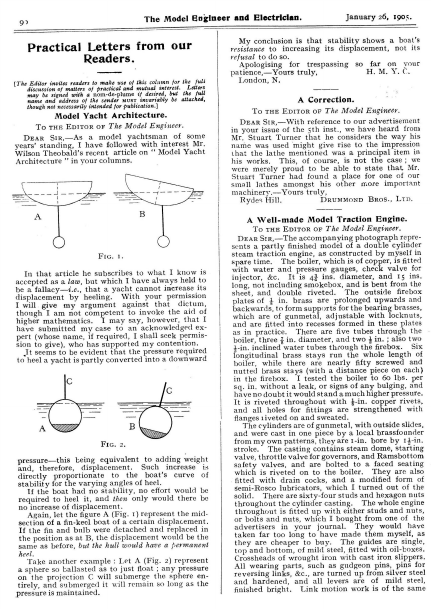
The Model Esgineer and Electrician. 9? refusal to do Apslogising ‘for trespassing so far on vour full (The gator,nanies rede to make use of this Cs for theLetters of matters of las ced and mutual4 the full desiredAae attached, besigned with a nom-de- plummeT ifinvariably may name and address of the send discussion January 26, 1905. conclusion is that stability shows a boat’s resistance to increasing its displacement, not its Practical Letters from our Readers. H. M. Y.C. patience,—Yours truly, London, N. ere: though not necessarily intended foF ‘publication Model Yacht Architecture. A Correction. To tHe Epitor oF The Model Engineer. To THE Ep1tor oF The Model Engineer. del yachtsman of some DEAR Sir,—As years’ standing, I vsee with interest Mr. DEAR S1R,—With reference to our advertisement of the 5th inst., we have hear from in your issue Mr, Stuart Turner that he considers the way his Wilson Theobald’s recent article on ‘‘ Model Yacht Architectur”e’ in your columns. ur d small lathes amongst his other more important machinery.—Yours truly, DRuMMoND Bros., L1D. Rydes Hill A Well-made Model Traction Engine. To THE Lee or The Model roi eee Fic. 1. In that article he subscribes to what I know is have submitted my case to acknowledged ex- pert (whose name, if renedy I shall seek pee peace it seems to be evident that the pressure a downward my conten sion to give), to heel a yacht is partly converted into nutted brass stays (wit s in the firebox. I tested the boiler to 60 lbs. per sq. in. without a leak, or signs of any bulging, and have no doubt it would stand a much higher pressure. It is riveted ig eg ree with 4-in. copper rivets, and all holes for fittings are strengthened with flanges 1iveted on and sweate The cylinders are of gunmetal, with outside slides, and were cast in one piece by a local beageieaner y Fic. 2. pressure—this being equivalent and, therefore, displacement. thi If-in. to adding weight Such increase pee s h stability for the varying angles of curve is of f the boat had no stability, no Stork would be required to heel it, and then only would there be no increase of displacement. Aga in, let the figure A (Fig. 1) represent the midsection of a fin-keel boat of a certain displacement. If the fin and bulb were detached and replaced in the position as at B, the displacement would be the same as before, but the hull would have a permanent . There are sixty-four studs and hexagon nuts throughout the cylinder casting. The whole engine fitted up with either studs and nuts, ba Spee is or bolts and nuts, which I bought from one of the heel. Take another example: Let A (Fig. 2) represent abe toga so ballasted as to just float ; the projection C will submerge the Pp iiely, and submerged it will remain so long as the pressure is maintained. and harde finished bright. Tink motion work is of the same
February 9, 1905. The Model Engineer and Electrician. The Society’s Conversazione. By “ONE oF THE FivE HunpDRED.” 1 (Continued from page 113.) ESSRS. WHITNEY had an excellent show of engine fittings, steam trical goods in the pressed = in plant was motio Mr. in A. pumps, Large use H. to and Hall. A eleccom- show the models Avery, Wells, exhibited several motors and dynamos, and a very excellent show of electric fan. of Tunbridge Stuart Turner’s high“eaPeEtt engines and engine castings 137 ran several of the models—notably the G.W.R. and L.T.S.R.—on their own and the Society’s tracks in the lower hall. i and parts for these i , and w able interest. The tool world was created consider- present in great form Messrs. Geo, Adams (the Pittler Co.), High Holborn, exhibiting lathes and a large collection of sma all ich may te specially mentioned the new pee eg one of the “ A and B” tools, also drilling saaehiaee Messrs. Drummond Bros., Ltd., exhibited one of of the Society, demonstrating its points aud show- ing the new milling shortly pom on wh attachment, which will be the market, cutting a bevel Power ha cksaws and other engineering appliances were exhibited by the Fairbanks Company, of City Road, and Messrs. Leyland Barlow, of Manchester, sent a small power-shaper, which was universally admired. Mr. Edward Hines, of Norwich, was represented at the Conversazione ‘and exhibited a number of his fine tools, Lo uses of which were demonstrated to all and sun Messr: on, Griffiths & Co., of Ludgate e of Pecrsae Boys’ new es’ lathe, and several cases of their section. Mr. Loui Mr. J. W. Barber, M.I.M.E., Fic, 2.—Mr. FRECKER’S MopEt SAILING YACHT. was much eau appreciated, all sizes being represented, ee 6 of his famous from the small model fe) G.N.R. 251 he has lately completed to the order of a customer. The Central Electric Co., of High Holborn, exhibited several spark coils andar lators, and Messrs. e ee T. W. ach PAOUpE on & Co., a collection of their specialities,adil, lamps, instru- ments, accumulators, dynamos, and motors. ie H. E. Ablett, of octet Bow N., demonrated his desi oof Messrs. W. H.” Ha:arling, ths etyoat manufacturers of drawing instruments, were in evidence with a splendid show of their oods. The Model Manufacturing Co., of Addison Road North, had a very good show of some of their best work, a model L.B.S.C.R. single, a model Atbara, and other igen aa Mr. J. P. Meaden’s mo engines, Hart, Mr. y. C. Tovice Mr. W. Muncaster, Mr. C. On the same table 14 scale S.E. was to be seen, for the puilding of which they supply castings. Small scale locomotives, carriages and wagons in an abundance were shown by Messrs. Wright, Clark and Wallis, of Southwark Bridge Road, 8. E., who by Mr. J. Russell, Mr. W. Ss. Barrett, Mr. H. G. Barnard Ww. Mr. E. W. Hobbs lent a model fire escape and some photographs of his home-made tri-car. In the electrical section Mr. H. Hildersley, with several fitments, Mr. Geo. Gentry’s s medical battery, Mr. N. Dufty’s material, Mr. J. W. 4 s referred to. Messrs. F. pee & Co., d collection of cede “appanatus S Mr. W. Brooks also exhibited his patent draughtsman’s curves. . H. Solomon, and Messrs. Bassett- Lowke & Co. also exhibited india railway coaches of various kinds. Amongst the models not already mentioned were a model Mexican gunboat, Mr. B model stationary cay marine steam cranes and other secti and other interesting novelti By the kindness of —8,. Napier, of motor car tame, one of the tables in the large hall was complete, roller bearings, parts of the steering gear raulic regulator, a fan, mechani complete gear box. minimise the overcrowding in the large and small halls, some excellent models were centred on the tables in the reetashaient room, where the
Fic, 2.—Mr. FRECKER’S MopEL SAILING YACHT.
The Model Engineer and Electrician. Model Yacht Architecture. To THE EpiTor or The Model Engineer. Dear Sir,—Replying to ‘H. M. Y. C.’s”’ letter which appeared in THE MopEL ENGINEER of January 26th, I am afraid that I must still hold to the recognised principle—‘ that a yacht cannot increase its displacement by simple heeling. pressure required to “HM. Y.C.” says: “ The heel a yacht is partly converted into a downward x ‘is’? I think should be read pressure.”’ There is not the slightest reason why “may be.” the pressure required to heel the boat should not be Referring to Fig. 1, in an upward direction. let W represent the force and direction of the wind which is heeling a yacht. March 2, 1905. A Simple and Effective Surface Carburettor. To THE Epitor oF The Model Engineer. enclose a drawing of a d (6 ins. by 4 ins.) carefully cleaned and tested for leaks. The essential feature is the provision of an automatic air inlet and level gauge, which adjusts itself to the level of the petrol as it ‘H.M. Y.C.” wants some of this pressure converted into a downward Well, the only way to accomplish this downward pressure as at P, which, if it existed alone or in conjunction with W only, would increase the t this cannot be—w must be indisplacement ; cluded as well. , what about Fig. 3, in which W is reAccording to solved into P upward, and w? “HLM. Y¥.C.’s” argument, the displacement in this case is decreased by the upward pressure acting The only possible way of actually ‘‘ increasing at P. the displacement of a yacht by heeling ’’ is that due to some outside force acting in a downward direction. In the lake district this is frequently met with when a current of air comes down the side of a mountain, and does actually exert a downward pressure on the hull and sails. Fic. 1. Ww . Ww collar ; Floar Fic. 2. pa A SIMPLE SURFACE CARBURETTOR. w is used up, thus requiring no attention after the WwW | engine is started. Fic. 3. w P With regard to ‘““H.M. Y.C.’s” theory of the sphere, here, again, he says, ‘‘ any pressure on Cc will submerge it.’? ward pressure.” ‘This should read ‘‘ any down- hope I have made this clear, but at the same time I should, if convenient to ‘‘ H. M. Y. C.,”’ like to be put into communication with the expert, as an amicable discussion on such a subject naturally appeals to me.—Yours truly, Kensington, W. W. H. WILSON THEOBALD. The air inlet consists of a piece of 3-in. bore thin glass tube (aluminium would be better), which fits a close sliding fit through the brass collar soldered in the lid; it should be ground in with fine emery and turpentine, as glass tubing is rarely of the process. It is as well to start with b i-in. bung and pare it down to suit the weight of the glass tube. . The mixture exit, as can be seen in the sketch, rge bore tube soldered to the lid passes u which, together with the coarse wire gauze soldered to the brass collar, prevents the petrol splashing up and being carried into the supply pipe and preventing a uniform mixture. The carburettor works well at 400 charges per
The Model Engineer and Electrician. 258 F. S. Yar a piece of copper with a terminal soldered on the end. The bell was fixed over bed, the plug switch was just out of reach, and the batteries (two Leclanché cells) under the bed. I fixed one wire from the terminal on clock stand to switch and then on to the bell, the other wire was wound tightly on the stout wire on clock to battery. The clock’s alarm may be set for any time. When the hour is reached the clock alarm begins to ring and the ee ees | Model Yacht Architecture. al THE Epitor oF The Model Engineer. —If a yacht be given a list by shifting ae ballast within her, the displacement will not hav been altered by the operation, for the ae at it does not alter her weight or put upon her any thrust additional thereto. t the case is different if instead she be kept Alarm Brass o head LL] (0 ¥ Plug March 16, 1905. minutes of a strong electric bell won’t wake him— well, ee try artificial respiration.—Yours eb had a lug of copper fixed on one end, to the alarm’s winder at back of clock. I then made a stand tor clock out of a piece ofwood, with slots cut in it to take clock legs; upon this stand I screwed down winder End of wire delachah/e SIrip of sheel copper ims} Slols fo lake clock legs Mr. Linton TWEDDLE’s ARRANGEMENT FOR A SIMPLE ELECTRIC ALARM. stout wire revolves till it hits the copper on stand, then a circuit is set up and the electric bell rings till the sleeper pulls out switch. To set, push up ore wire an inch or two from copper and heeled by a wind, for.it will increase her displacement thus—whatever the direction of the wind fix his idea allows the user to detach the communiselion wire and use clock for other purposes.—Yours truly, Hammersmith. Linton TWEDDLE, A Simple Electric Alarm. To THE Epitor oF The Model oe DEAR S1R,—Seeing reeeasy column for March 2ndfrom Mr. letter in this Saltaire, 1 heiiId like to make a few vermacks none my alarm clock, which was describedin the M.E. for Tobniaey znd. The long hand remains several minutes after contact touching C for larm, it was to be supposed S attachment, so that it could be put to any clock As to the working of it, I have used my alarm almost as long as Mr. Saltaire, with no harm to the clock, and it has never yet failed to work. As to the ring not being long enough, I am afraid my friend must be a second Rip Van Winkle; if three across her, some i upon her in a dir eae of its thrust must act inclined downward—i.e,, purpeadicalar to her ail surface; otherwise she would right herself. This component tends to force her in its own direction but (see diagram)
259 The Model Engineer and Electrician. March 16, 1¢o5. may conveniently forces— be resolved into two Queries and Replies. smaller [ ditention fs Bpecially directed to the first condition given below no notice will be taken of Queries not complying with the and the iee fee hate corner of lay hold upon them inst of flowing over them werd aaeimpeded aati “swaetiy itself mainly in a f she were careened by a line made fast to the mast and exerting its careening pull horizontally, oe would not be altered because the constituents of these pulls would one another, leaving exactly neutralise unbalanced vertical thrust Stability has nothing to d t ion. tive of the stability.— Yours London, E.C. the lope ** Query iinmnaiioebut those velatine40 the Quertes Department. a 9 other should be omatewad in the same envelope. 4° Bithin the scope of Hiss journal areertiesreplied Queries on subjects dealing underthe following conditions :—(1) different sli; should bi werilten: on name with distinct ie only, MUST 5 in andthe sender’s i (2 by post wherever possible, to keep spondents are recommended a copy of t Quert. (5) A stamped adarcesee envelope (not post-card) refe: “ Queries and Repltes a should invariably be enclosed, and the current ” cut out from the advertisement pagesas ofposstble after (4) Quertes will be answered as early elapse before 0 fss of a few days must usually gece pt, but an interval who require (5) é@ Reply can be forwarded. n answer inserted in this column should under: Reply can be publis,shed. The weeks must elapse inbeiorethe this solumn cannot be guaranteed. (6) AW insertion of Replies MODEL HE R, 26-29,Poppin’s Court, Fleet Street, ‘London Cy Queries. sshowa the actions are as above set forth and are irrespec- be eters containing Queries dleecttions hale sta ted. b stituent would er goer ree V if it could e addressed to The fatoing areea ected from the Queries which have been replied Boat. S. C. (Shore3964) Accumulators fer Electric fitting up an Sectie boat. I nily truly, Jy Te A Delicate Galvanometer. I am thinking of volts 2 amps. to drive it. The have oat motor which requires 8inside hullis about 4%ins. What ham) w: epth you advise- To THE Epiror oF The Model Engineer. lor vertioalt mark S1r,—I have just meas a delicate ealvane eter asNoel al in No. of the M.E. series of hanélboo only difficulty was with the maeneie.nestle, I obtained one from a dealer in electrical apparatus, but nearly delicate enough. one from iece of found ic. have practically no tools, it was impossible to make a brass cup on which to pivot the needle. I got over the difficulty, however, by bending ithe spring into Armstrong vessel of their Sone theletEeaen cokeinalso thereis anyuu would not think I yapMessrs. me know any special poin i & Co. as a battery for . Woul the shape with a ninmnena-akaped drill, nearly through. shown in the sketch. In the centre I drilled a hole Great care must be taken not to go right hepa as this would render the needle NEES. The ni was ae hardened in the usual w: It f great importance Tor to magnetise it siconciys as this would make the controlling force is means fine pi flat plate, instead of the eylinder but it.will increase the internal of current you GALVANOMETER MAGNETIC NEEDLE. unnecessarily powerful. I made my first point from a fish hook broken off just below the barb. I found this gave better results than an ordinary needle. I notice in the instructions that one is told to o: make the pointer partly iu What is the advantage of using ot counterbalance on the other side is unnecessary. I with a as front, and have placed a small 4-v lighted, slranninates back, which,sowhen lamp at thevery brightly, that the slightest movethe scale eedle is vis:e Hoping these sugment 0: gestions – ‘be of use to your readers.—Yours London, W. are experimennts ; it will not ance matters very much if youCo., taking *very small current. Write to Messrs. Armstrong & (3) charge volts &somewhat requiresv5oltage (4 -volt aécumulator and enquire. e battery There is no harm in havi it. Tegulate:it he a small resistance,wand cells can always higher; you down use. in write 13ss21 Condenser Failure. J. D. A. (Sevenoaks) the following queries: tend to run ()‘a have a en Leyden j ar, about veins. high and made.8 ins. diameter, en con- in apparently good condition, profession ally only acquire a very feeble charge, nected up to Wimshurst it will be see!n in the Anteriorot jar. nd,if so, is it useless?> S the (ey- ‘there danger of can in overchiarglng Le ai occasional flash is to and bis e jar very much lighter. truly, reste fance’o the ce! . H. STEPHENSON. will they only receive that amof char; ) Can ? allows and no more THE Mop 1 ENGINEER 2 haveof inexpensive slecticlty making apparatu ir e the description of the various far various experiments anmetoa befullPerfor med with a Wimshurst, d experiments especially such as aisletc Tectur a 1) The jar is Cyidently parerited or cracked, and therefore it is pracdischarge wouldtake place betweenthe tntoll!coatings;3 coat a new jar, and tically useless. The Bes hing to doAllis to condensers are liable to uals the oldknob andcover. (2)strain on the insulation between k down, as there is a continual
x wv bo March 23, 1905. The Model Engineer and Electrician. with cast-iron packing rings. The connecting-rods are of special cast steel, with steel gudgeon pins and white metal surface bearings. By making the reciprocating parts of the very highest class of material, the weight has been reduced toa minimum, and, accordingly, the vibration is scarcely perceptible. The exhaust is partially water-cooled, and is led through the bottom of the boat. This does away with all noise and smell. Great attention has been paid to the carburettor and mixing arrangements, to ensure steady running and economy of petrol. The governing is effected by a centrifugal governor on the cam shaft, connected to the thrott le valve Now, when a boat is hard ee the ee t of the boat, combined with the “twist” of being seeeneailyonja the sailcloththen sail, results invertical; the the pressure and zontal than sail is more downward than sideways. n other words, the pone may—and often does— ith greater force Pica it exerts in driving the ‘qessel18 leeward. the “ umOf course, there ave sails—notably force on the vessel; but these are are not used in ordinary practice.— Yours ee Ne Ss To tHe Epitor or The Model Engineer. DEAR S1rR,—I read with interest the remarks made by your Ble contributor, Mr. Wilson Theoinherent in all reversing propellers. bald, on the question of the resolution of the wind’s acht, producing on the = of a we force acting T is of bronze, and of the well-known “ Thornycroft ”’ design, which has proved so successful for many years where high speed and efficiency are desired. Now, Sir, the cottaat aguitied‘of the problem heeling and also dow pre depends simply upon a right interpretation of laws of mechanics. If your space permits, I should just The Society off Model Engineers. [Reports oF meetings should be sent to the offices of THt Moprr fcuar issue if received a clear nine days before its usual delay, and will be inserted in any par- ate of publication.] London. UTURE Meretincs.—The April meeting will be held on ‘the 13th of that eis when Mr. Alfred B. een (Fellow of the co will lecture on and 10 unifs ees Society of London) conduct experiments with liquid air and liquid sutonie acid. May meeting is fixed for the 18th of that month, when a lecture will be given by Mr. Eric S. Bruce (Hon. Sec. of the Aeronautical Society of Great Britain), on “ Airships, Balloons, and Flying Machines.”” Further particulars of these two lectures will be announced later.—HERBERT RippteE, Hon. Sec., 37, Minard Road, Hither Green, Practical Letters from our i the correct angle at which they may set their sails Readers. to suit {The Editor invites readers to make use of this column for the full discussion of matters of pradeal and mutual interest. Letters may be signed with a i oe Pl name and address of ihe sen e tf desired, but the full mua uivaranly e attached, though not necessarily enejor publicatio Model Yacht Architecture. To THE EpItTor oF The Model Engineer. DEAR S1r,—I think that Mr. Li is wro— in his es ae pee that the oe eo usually press a boat down in the =A he e con- tends that when the direction of the wind is hori- zontal, the pressure on the sails is also horizontal. If this were one it — follow that the Le ey must always be in the same direction as the w How, then, A065 ie eaplaii the fact that a boat can sail to windward? The commonly accepted explanation is that the ressure on the sailcloth is at right angles to the satlcloth, the sai] being so trim me that this pressure drives the boat sideways I forward. any direction of wind, with the greatest effect. Fic, 2 Apparent wind 10 unifs ‘ L ax ~~$+Head way VAyaw The sketch in Fig. 1 shows the force of the wind acting on a yacht’s sails. Suppose the force of the wind on a plain surface = 10 units in horizontal direction .-. first resolve this 10 units force into one 9 units anneg square to the sail (assuming it to be braced flat), and another
now. Resolve the 9 units into one concern and gi units horizontal, producing simple heeling,more another downward force of 3} units, producing only 283 The Model Engineer and Electrician. March 23, 1905. parallel (which we may disregard) of 44 units acting to the sail. The 9 units is the force which is our If we extend this application of the wind’s force by considering its effect in a horizontal direction, producing headway and leeway, we can determine heeling, but also adding its effect to the displacement. ~ due to the yacht’s headway as shown in ~ NN 8 Fig. 2 igs. 3, 4, and 5 illustrate the method of obtaining the greatest propulsive force on the sails and the points P \ 90° ‘\ App. wind in bracing the sails too flat. The best angle the sai lis from Cr. line at stem = No. points of divided by 2. Headway. : 4 a oy f rom stem, Leeway. § cs 4 wei uni LOL wen ern 60° App. wind. is wind wNy Angle of sail. 4 Points, 45° 30° apparent Angle of sail. 6 Points, 673° 60° 85° App. wind. Headway. Leeway. . 83 .. 3% nits e+ we .. IO cae ,, as -» BE SF ae .. 8 2 If the yachts in Figs. 3, 4, and 5 were heeled over as in Fig. t, the 10 units would have diminished to the 8} units.—Yours truly. Barrow-in-Furness. ALFRED HILEY. of Nore.—The angle is measured at the heightcon- Angle of sail. 2 Points, 224° i 3 4 \ sane aan stashed i 30° 35° App. wind. . wae rounits “TO! wa oxy Headway. .. I . IR… I 2 2k 13 Written in mathematical language, the force acting square to the sail is 10 units x Cosine 6; and the force acting horizontal producing simple heelthe force acting downward ing — 10 x Cos. 20; and producing also more heel and greater displace- ment =10x Cos.@ x Sin. @ =10 x pis Be 2 this downward force is greatest when the yacht is heeled to 45°. parent wind is only Leeway. yo telligently. A Model Steam Lorry. To tue Epiror or The Model Engineer. DEAR Str,—In your issue of March 2andI noticed Alfced a model steam lorry described by Mr.a simple Harris. Might I suggest the addition of to imwhich might not only tend i
330 The Model Engineer and Practical Letters from our Readers. The Edttor invites readers to make use of this column tor the full gsc StOn of matters of bradicas and mutual interest. may be nee with a name and Letters nn e-PIlume if desired, but .the full ss of the s MUST variably é attached, though not pees intended for publicatio: _ Steering Gear for Model Yachts. O THE EpiTor oF The Model Engineer. E DEAR SIR, tie Poe is a new method of L <¢ ts. t is automatic in the working, and as oaovell a perfect way in which Veane edging = 1905. upward a little; vane disc, 1} ins. diameter, 1-16th ; brass wire for vane, 1-16th in.; tiller, 1-16th in, " spring wire. Slots. should be } in. long to allow tiller to play; rudder should be long perpendicularly, but narrow ; rudder area, about 4sq. ins. The vane disc should stand about fin. clear of deck, and the spindle about in. long. Dimensions given are not absolute, but all should be as light as possible. The vane is made of very thin ‘linen—not cotton— | Wire Disc - April 6, Electrician. her back on her course. Ifthe yachtis close hauled, beating to windward, and a tack has to be made off ashore, vane and tiller would have to be changed over; but if a course can be made without tacking, she will gostraight. The dimensions of the parts are as follows : vane area, 8 sq. ins., which must slant Rudder head sewn on over the edge of the wire, and then venested or oiled with linseed oil. The area of vane should be double that of rudder. If vane contains 6 sq. ins., rudder should be about 3 sq. ins.—Yours truly, HAS. R. WALKER. A Simple Electric Alarm. To THE Epiror or The Model Engineer. DEAR Sir,—Herewith I beg to submit pee lars of an electric alarm clock which I have made, Spindle and which has been wocking very salisisctortty for | —— Arrow showing direction of win Revolving disc Rudder head Fic. 1.—DIAGRAM oF CONNECTIONS. STEERING GEAR FOR MODEL YACHTS. to govern the sailing of a model. As will be seen, the principle is an adaptation of the vane. The ane is attached to the revolving disc, which fits over the spindle, which is attached to plate to screw to deck either forward or aft rudder head— aft is best. As will be seen, the revolving disc has small slots cut out close to the edge to take end of tiller; slots to be cut at every half point of compass; the disc is held in place by a small brass on. The practical working is as follows : Point yacht on the course intended, let the vane fly loose with the wind, then set tiller into slot in the disc, taking care, in all cases, to have it straight fore and aft ; then trim sheets to suit, and send her off. If she luffs or falls off, the vane acts on rudder, bringing Frame Wire of face Insulaled copper sirip Spindle of alarm Fic. 2.—A SIMPLE ExLectric ALARM. several months. It hasthe f regulating the time by the existing indicator of the clock. Take the hammer ot the alarm off, and through the top part of the flame screw a strip of insulated copper, and solder on the wire; then adjust it so
The Model Engineer and Electrician. 354 almost run down and left in circuit for three or four re is no discha: h battery; the galvanometer still current, and, if the battery is cut off for a few seconds, it will show a partial recovery. The zincs are ane cease by di ping them for }-in. in April 13, 1905. horizontal direction, and not perpendicular to the sailcloth of the vessel, as ‘‘ N.S.”’ be the case. points out should Second y, he has resolved a fectly horizontal force into a component vertically downwards, per- acting being apparently oblivious c' any Should they at ush. "require more amalgamation, this process’ can repeated. When not in use I remove zincs from electrolyte. I use about 142emp -hours of current every day, and always put the battery in circuit every day, if possiblevending the cells ‘‘ Lien it replacezincs. I tried Daniell and Léeckanctié cells ony takes about thirty seconds to ta ke “previously, but in the former case the zincs used to isappear in no time in spite of amalgamation, and in the latter case I got no current. 90° The installation above described works very well, andy. and is ver I use no other form of lighting. The approximate cost is 4s. a month for bichromate, 1s. for mercury, 2s. 6d. forsulphuric acid, and 5s. for zincs. I shall be glad to answer any questions in connection herewith. ' add that, owing to my being in GovernY may ment quarters, there are no facilities for erecting an engine and dynamo, which otherwise I should have done. a eekaie lly, L. FitzGERALD, Lie The Royal Maueetire Regt. Curragh, co. Kildare. to the fact that a force has no effect in a menserron Fig. 1 of his diagrams, the force of 4} uniits has a at right angles to its line of action. Of course, in vertical component which exactly neutralises the effect of the downward force of 3} units If, however, the wind pressure of 10 units be Model Yacht Architecture. taken perpendicular to the sail, and it be resolved, To THE Epitor oF The Model Engineer. DEAR S1r,—In reference to the much discussed question of the resolution of wind pressure on the sails of a yacht increasing its displacement, I quite as shown in Fig. 1, forces of (roughly) 9 units hori units vertically, will result. The he y Hence the correct method of determining the headway of a yacht for a given position of the sail, when the apparent wind is known, is as shown in Fig. 2. —Yours truly, R. Mitwarp ELLs. Dartmouth Park Hill, N.W. no THE Epitor or The Model Engineer. Dear S1r,—I have been following with interest the Demian in your valuable paper as to whether the wind acting on a yacht’s sails produces down- ward pressure as well as heeling. I feel certain that Mr. Wilson Theobald is right when he says that there is no increase of displacement caused bythe heeling of a yacht under the influence of a wind acting horizontall Your contributor Mr. Hiley endeavours to prove t that the displacement is increased by aws of mechanics. He has, however, made a mistake in Fic. 1, agree with your contributor, Mr. anes Bey that epends “the correct solution of the pretation of these laws is of the correct one. First of all; he has taken the pressure of the wind in a his reasoning, due, I think, to his forgetting that in the case in question the forces all act at one point. of THE MOIER, /ENaIThus, on pages 282 and 283 ich is NEER for March 23rd (referring to Fig.1 herewith reproduced), he says that the force ef the wind represented in magnitude and direction by line A B may be resolved into two forces, repreNow, this is not quite sented by AC and CB. right, for force AC acts at point B, and must,
April 13, 1905. The Model Engineer and Electrician. eae eerepresented by BD. Next he reves CBintoCF horizontally, and F B vertically pees again CF, which acts through B, should be represented by forces with w . we are now ic However, the [Attention ia Ape ay guid to the first condition given below, ned are acting up the sail, ae FB aatine vertically downNow let us cethe vertical component of BD; nc 355 Queries and Replies. d no notice will be directions therein si taken of Queries not comply lying with the ers containing Queries must marked on the top pare-hand corner of the envelope -‘ Query Department. i No other matters but those relating to the Queries wards, both at poi 'd be enclosed in the same envelope. Queries on subjects within the scope of this journal are replied this is BF acting vertically upwards. But the only oe downward force is represented in itude 1 direction and this is neu- to by post under the following conditions :—(1) Queries Dain with distinct subjects should be written on differ one side of the paper onty, and the sender's name tealised by the vertically upward fice BF, which scribed on t (2) wherever possible, spondents ies h fully dimensioned sketches, and Tecominels ded to keep a copy refer ) iss (4) of t. ‘amped addressed envelope should invariably be These, Co: ut slips, on n- MUS’ T be accompanied, from the will be (not e Qu post-card) so a ‘‘ Queries and Replies advertisement pages red as early of the curr as possible after e Edito Enc , 26-29, Poppin’s Court, Peet.ieet, Leadon, C.] The soloing are selorted from the Queries which have been Seine ecently :— [13,750] Accumulator Making. J. R.H. (Aldershot) writes: T should be glad if you could help me over the following difficul:ties: ( ~~, Fic. 1. / is equal and opposite toit. Therefore, there can be no increase of displacement caused by the heeling of a yacht under the action of a horizontal wind. In conclusion, I should like to say that this iis not put forward at all in a carping spirit, but simply with the intention ofa a away any doubt on the subject.—Yours truly, Carlisle. G. TREVOR WILLIAMS, s ti ebonite cylinder. i Tt”,ke as encourage model-making The bag is decayed and the “ blotting Peer mal (1) Fit a thin yulcaniss lid to the cell 0 that it is far sinus, The Fourth ‘‘ Gauge’? Competition. in all its down to samito ing is gauge, with screw adjustment, to Ss, we offer to send an every ea who 1 sends us improved slid- for insertion in our scription ‘of any model, tool, or piece of apparatuseourn goo! he has made. If preferred, any other tool, book, or other article to the value of 6s. 6d., will be sent in place of the caliper gauge. Entries should be of the desired. article, If and stating other tha: exactly what iper gauge tool is e- quired, the md number of the tool in th firm’s catalogue from which be obtained should be mentioned. The article should be writ on one side the paper only, with t e an address of the sender on the back. The photographs and separate sketches enclosed with the contribution paper, ee you call it, and tinfoil appears to be the remains of a conden: nate ras)Sozwatt- Dynamo Construction. W. J. P. (Clapul wind and between every layer? Is it sufficient iu been on or should I use shellac varnish between each wind wire will find some useful information on ncking ‘field- magnet coils iin THe Move. ENGINEER for December 17th, 1903, page 58rre yerish on each layer, this effect. The Competition will close on June 30th only varnishee the top layer. not pu t paper between eac ach lay will take up valuable space oO there is no need for it, and it
The Model Engineer and Electrician. 378 Practical Letters from our Readers. April 20, 1905. of boat on the water line when at that angle; and also the inclination of the plane of the sail to the direction of the boat’s motion ?—Yours truly, WwW. (The EditorHere! readers to make use of this column for the full dis. m of matters of practical and mutual interest. Letters name and address of the sender muST invariably be attached, though not necessarily intended for publicatio: S Perfect Scale Model Locomotives. ‘© THE EpITorR oF The Model Engineer. Model Yacht Archicectute. Dear Sir,—Having been a reader of THE MopEL ENGINEER since the first numbe er, I need hardly say that I am greatly interested in model making, Sir,—I have been much interested in the discussion which has been going on in your paper, and while‘‘ W. J. T.’s” explanation is both clear read the particulars, and looked at the photographs To THE EpiIToR oF The Model Engineer. and have made very many of all types. I have again and Dae of that magnificent scale model .N.R. Co.’s locomotive Pe ed in your issue of March 9th, made not help thinking how by Mr. Baines, and can- many of our readers (in- chiens myself) would like to do the same. So I merely suggest that you should bring out n THE MopEL ENGINEER a series of articles, with full particulars and dimensioned drawings ofevery single part of some similar perfect scale together with apt oebe the building. this to you, model, I suggest as probably you would more easily obtain complete prae drawings from any large compan Perhaps you will publish these suggestions and see what hol where would be from other readers for such a With regard ie the type of model, I would men- tion an W.R. Webb’s three-more compound, or one of the latest Midland expresses, Anyway, I would strictly adhere to this—let it be an absolutely perfect scale modelin every detail, such as odel of Mr. Baines. —Yours faithfully, Fie. 1. and mathematically Fic. 2. correct, the P: €.$ A Novel Miniature Traction Engine. To THE EpITor oF The Model Engineer. R,—My fourth model of this kind is n i Bs Kingston-on-Tham a mpeiabare “fagtion engine, which can be put out ft geam and used as a stationary engine, it having question appears to be one for the physicist to decide —viz., what becomes of the particles of after they strike the sail. air ot 2 i=} lay & i) OQ me n < ~ air to be per- A ® me ot 1,200 cos, 30 lbs. =600 1/3 = i pressure would =] Q the particles of z posing at right angles to the sail Ibs. about. The downward 60 = 500 lbs. whichis, approximately, enna to the weight of 8 cubic ft. of wi If the boat is to “tt. long, the horizontal section on the water line might ak something like Fig. - giving an area of about 200 sq. ft. The boat would, therefore, be. depressed 8-200 ft. _ in. roughly, or 1 in. if the sail area were 800 sq. ft. 1 me of your nautical readers supply the following information—viz., angle at which the mast would beinclined by a 2 semiile an hour breeze, the sail @area, and the area of the horizontal section A Nove MINIATURE TRACTION ENGINE. a pulley on shaft. The gilt covers of Fry’s cocoa tins are used for wheels; a cartridge case is made use of as a chimney. The cylinder and piston are made from brass tube, the disc crank and cog
The Model Engineer and Electrician. 394 A Design for a Model Sailing Yacht. April 27, 1905. Sails of best quality model sail cloth and taped. aio > aa quality model yacht fittings, silver-plat The hull.s be painted brown to just above water line, top sides white with gold line just below HE design given herewith of a 42-foot linear rater mode] sailingyacht has been sent to us by Mr. R. P. Kittchingman, of 11, Marlborough ‘Terrace, Kirkley Street, Lowestoft, together with covering boa The Parricutat dimensions of the model are as follows :— the following building spec iGeation of the same :— Length L.W.L. The keel, stem, and stern-post of elm should be all Beam extreme Beam L.W.L. sided and moulded as per drawings (Figs. 4, 5, 6, .. De ee -. 396 ,, ava ae _ oe os .. ERG Ile? yy ,, : 8-0, 24°7 Ibs. | \ Fer Inclubiing lopseil 6 ICE : Less /opsail Scale of inches (6) By Fic. 1.—A Mover 42-Fr. LINEAR RATER SAILING YACHT, The frames to be of pine spaced 3°3 ins. from centre to centre, }-in. sided and 4-in. moulded. Planking of mahogany, 4 in. thick. In- — of pas, # in. square. Mast partner, } in. oe. The fashion piece of Deck of mahogany, tiin,i. thal, Fastenings are brass screws. Caulking—Al!l seams payed with gold-size putty. Painting — Boat thoroughly painted and varnished inside anct out. Ballast—Lead. Spars of pine and varnished. Draught (extreme) 8-35 ins, Overhang fo Overhang ait Displacem 70 oe .. ee ,, C.B. aft from forse ofstem atL. WwW.L. 21°68 ins, C.L.R. do do. Total sail area,oy. R.A. =1664″2 5 Sq. ins. 23°39 ,, Area of fore oe =499’5 sq. ins. 39°—— S13 65 +3 eee 39 Rating = £97. The boat is shown fitted with Mr. Kitchingman’s B. or75G. 4d. 0°54/S.A,
April 27, 1905. | | The Model Engineer and Electrician. | \ 393
The Model Engineer and Electrician. May 4, 1905. between them at such a distance as to allow the ends of wires to reach cog-wheel C, and then binding them together both sides of screw B with cotton thread, then placing the screw B back again and screwing it up tight, and adjusting the wires so that the cog- wheel C will come in contact with them when it moves forward—which is caused bya slot in centre I then brought and a spring D at the back of it. the other end of wires A A inside the clock to two holes E E, and for the outside connections I got a piece of copper F, about } in. wide and 3-32nds in. the ends to be for allow to enough long thick, and bent down (as shown in sketch), and making holes E E for the wires to pass through, and holes for the screws GG and legs HH (the screws G G take the place of the ordinary legs), and insulating both Dear Sir,—Graphical demonstration of the fact that wind acting on the sails of a heeled yacht causes her displacement to increase does not’seem to satisfy your readers. Perhaps some of them may care to make the following experiment arranged as in the diagram below :— ‘ 3 H H I EXPERIMENT SHOWING INCREASE OF “MopEL YAcHT DISPLACEMENT WHEN ends of F with stiff paper. For the legs 427 ; To THE Epitor oF The Model Engineer. HEELING. got two pieces of steel wire (K K) and six brass nipples—three for each leg (which are used for cycle wheels). I put athread on the wires K K, and screwed the first nipple on each wire, filing them down So that they would have the appearance of a bolt head. I then placed them in nipple, after which I placed the connecting wires between the second and third nipple. This has worked much better than having only one wire, as the frame L is of cast iron, and does not allow the current to pass through very freely ; and I have also made the other connections of brass and copper, instead of spring steel.— Yours truly, WALTER COPE. Crewe. Model Yacht Architecture. To tHE Epitor oF The Model Engineer. DEAR Str,—I think the fact that the wind pressure on the sails of a yacht adds to the displacement may be proved in the following manner :-— against a straightPlace a set-square A BC edge X X ; now press against the set-square with a stick Q P in the direction of Q P, and the set-square XX will move along X X from A to C—that is, if Now, in thecase ofa yackt, we have much isfixed. the same arrangement. AB represents the sail, the force along Q P represents the wind, and KX X xX 2 the other. pan; then di blast of air horizontally upon her sails. If this treatment causes her to descend, then the horizontal blast must have an unbalanced vertical component tending to increase her displacement.— E.D EXPERIMENT SHOWING A light chain hung from the above weighted pan and extending nearly, but not quite, into contact p Q with that pan when the scales are horizontal, will serve, in the rise of the weighted scale, to represent the increasing resistance of the water to the in- INCREASE OF creased submersion of the hull.. A further refinement would be to so counter- MopDEL YACHT DISPLACEMENT. WA xX represents the resistance of the ship to leeward e only real difference in the two cases i is that the yacht is only partially stopped by its resistance from making leeway. But the principle of motion is the same in both instances, and as the set-square moves in a direction AC, so the yacht, moving the same way, sinks deeper in the water.— Yours truly, London, S.W. . J. Huck. balance and support pivotally on the scale that she should not merely lie over on her bilge, but rest vertically to commence with, and assume an in- « If three or more of your readers would make such a test, independently of one another, and report results to your office, we might get a little nearer to clined position under the action of the blast. a solution of this much debated problem. in arranging the apparatus, the dictum attributed to Sir Benjamin Baker should be borne in mind by the experimenters—‘‘ There’s nothin more misleading than figures—except facts.’”?— Yours faithfully, W. Jj. T. London, E,C.
May II, 451 The Model Engineer and Electrician. 1905. force of 9 units, which acts square to the sail, by virtue of the wind being a movable bombarding Practical Letters from our fluid. Readers. If Mr, Ellis will study the effect of wind supporting a kite, to which even weight may be attached, he {The nee invites readers to make use of this column for the full discussion of matters of practical ee mutualinterest. Letters nom-de-plume if desired, but the full mathe signed mare invariably be attached. nas and address of “ihe senderfor Met ugh not necessarily intended public: Model Yacht Aranitecture. To THE Ep1Tor oF The Model Engineer. DEAR S1r,—I notice Messrs. Ellis and Williams do not quite grasp m interpretation of what occurs Ww! will see in it a closely allied problem, atid) it must be admitted that the ground string has an upward pull, which is aad with the downward thrust on the yacht s Regarding the”last remarks of Mr. a I fail to see theirimport. If they are intended for a correction I entirely disagree with the oe Regarding Mr. Williams’ criticism, I cannot concur with his attempted correction “to clear away any doubt on the su ect.’ I wish Mr. Williams had proceeded further, and in addition to his showing that the force acting Rega ding the wind ee acting on the yacht m yself) has eae i ot nardileel to the sail pene balanced by the resolved of the Pe force, downward component proalso applied his proof to the wind’s force a proved that the forward component producing y was A pie a by the force acting parallel hea to eesail. re the subject in THE MopEL ENGINEER, pages 282-3, March 23rd, and main i correct, and the principles are the same as are em- ployed in problems of a similar cieradien, although in this instance the exposition may be somewhat original.— Yours truly Barrow-in-Furness. explain what makes it rotate if the wind does not exercise a force at right angles to its direction. . I (which really bomb identical with what would occur if instead the force was applied by pulling attached to a fixed point horizontally at a rope itis here that the misapprehension occur: My critics’ arguments would be quite een if the yacht were simply heeled over by pulling hocieeniauy at a rope attached tothe mast at a fixed point. ALFRED HILEy. To THE EpiTor oF The Model Engineer. S1r,—With reference to he letter originat- wind’s direction. ing your columns on in the discussion now going as to whether or nota yacht leans: its displaceand Mr. Wilson ment when heeled and under way, Theobald’s rejoinder thereto, wherein he challenges the authority I quoted as supporting my contention in the affirmative, I have now the permission of the Editor of the Yachtsman, the expert in question, to give his name.— Yours caaaieac BH. Me ¥, & Stoke Newington, The force, 4} units, acting parallel to ee Scale Model Locomotives, THE Epitor oF The Model Engineer. we have had Dear Sir,—With the photographs followed by Mr. of late in THE MopEL ENGINEER, cea splendid model, our locomotive Pr I e been roused. think “P.C.S., his Ase Toth, letter which appeared in the issue forwanted ; also has just brought to light what was that such a series of articles would be greatly of appreciated. Personally, I should choose one Atlantic such as the N.E.R. designs, the sail, has merely the eae ip effect of moving the perpendicular force of g units up along the sail, being followed up by more similar forces con- type express, or other equally smart type.— Yours j. W. truly, Great Harwood. tinuous If the sail were a frictionless inclined plane there ECORD SuHip’s TELEPHONE SystTEM.— The largest telephone He” on any ves a 9 units into as you then obtain the component of an actual be and regular exchange both an ip iecaonamenieation ith the 1can t system. Th system ‘of any city in which the ship may an installed on the Ss;
548 The Model Engineer and Electrician, Practical Letters from our Readers. [Anenion 3ts napetaly citasten to the first condition given below otice wilk be taken of Queries not complying with the directions therein sated. Letters containing Queries must be The Eittor tnuites readers to make use of thts column for the full ascussion of matters of practical and mutual interest. Letters may be signed eae @ nom-de-plume i} desired, bus the full mame and addr of the sender phainvariably d @ attached, though net necessarily tniended for publicatio Model Locomotive suite s with distinct subjects should be written on differ one side of the slips, on paper only, and the sender’s name MuST be m the back. wherever possible, often thought of bringing a Queries wit! ld accompanied, ly dimensioned sketches, and corre- spondents are recommendes cep a 0; Queries f ref e. (3) stamped addressed envelope (noi post-card) little matter before ¢our model hould invariably be enclosed, a up to those large enough to ride behind. in real work, arihandl a matters but those relatingto0 the be eyinaie same envelope. i postt under the following conditions :—(1) QuQueries ened Queries on subjects within the scope of Ess fournal are replied To THE Epitor oF The Model Engineer. Sir,—I h June 8, 1905. Queries and Replies. Co ” cut out issue I suppose from s the will be and also a “ Queries and Re advertisement pages of the wered as early current as possible after i versing gear—the linking up varying with the load, igo and weather conditions; but in do no such thing. As a rule 9, Poppin’s Court, Fleet Street, London, The following bee selected trom the Queries hich “have been replied ecently :— Gat rlpolar Armature Winding. C. R. R. (Gosport) lease describe how to wind and connect the wire any wonder at us being beset with the boiler pro- this: connected up the t gear why reversing’ as the speed gear not so have as increases? to I a link think it could be managed s not to interfere with reversing and, of course, wguld be adjustable for different speeds. This and cet the brushes in a tripolar armature motor, of which I enclose a sketch (nok reproduced). ture in one Is it necessary to have the arma- piece You will find an explanation of the winding oea Epolar ane ture, with illustration, oe page 26 of our handbook No. otor: to, “‘ Sm: The brushes should be. fixed i various positions until‘best effect is obtained; orif the brushes annot be moved, the comma tor can be shifted round on the shaft instead. either one wayo: Tra, 190] – Seale mate 1 Lecomotive. ‘‘ Nimrop (Shetwerd) sirites Would you kindly answer | the following question with regard to the 2-in page2 74of “ The engine carries comparatively low-pressure steam. Perhaps some of your readers will criticise. —Yours truly, Jj. R. Steering Gear for Model Yachts. to see how the sketches could be misunderstood. (1) Vane must be elevated enough to catch the wind even at the excessive heel of 45°, which seldom occurs unless yacht isstruck by a very hard puff. ° Bassett-Lowke fo} J. & + x To THE Epitor oF The Model Engineer. DEAR Si1r,—I have much pleasure in replying to Mr. Savage’ ‘s letter in the issue of April 27th last, peearding the steering gear for model yachts. I fail orthampton, or {13,804] Telephone Caamactian. J. A. (Ardrossan, N.B.) writes: I am constructing three telephone instruments would be esteemed. direct, as per dotted (2) Running invariably co ack befor at _the wind, once on the vane e, whether luffing or falling off. (3) Answered by No. 1. (4) No change in boom need be made, but it must bi dup a little to clear va his own steering gear he will be fully satisfied with the result. have presented the system to the inspection . the public, that all may use it who care to o.—Yours truly, aistow. Cuas. R. WALKER. Turner, to connect house with saddle room and workshop, which are nearly on wiring, or making a suitable switch? A sketch, speed. Stuar weight of the eee engine complete would be about 8 cw if convenient, Would you recommend running the wire ilding ? line, or round The best arrangemen adopt would be an inter-communica tion system, such as iustrated on page7’77 of the sixth edition of our handbook, ‘ Telephones and Microphones”’ (ready in a ie weeks). Run the ine wires inside building, unises you cani sulate them pretty Ww [14,089] act asnnton for Small Boat. L. B. (Aintree) electric motor I intend to bi for odel boat, about 20 ins ong and about 5 ins. to 54 eam? hat scale should the drawings be made for the Manchester type with drum armature shown in ook, “ Sm vy] os and Motors”? Also what wire for winding F.M.’s and armature if the F.M.’s are made of wrough n. Fleas , leave a goo gin for armature wire, accumulates or cells? the latter, at kind ? Make the motor to the ro-watt veh It should be series wound, We advise you to use No. 24 gauge double silk-covered wire
32 The Model Engineer and Electrician. Practical Notes on Model Boat Building. By T. Locuors. MONGST the foremost of out-door hobbies and cl gee is model Le aa kinds of modelc: model, with all its ree There are three (1) The extibition fittings, everything to x very near scale, and which is only fit for show ; (2) the sailing model ; and (3) the steam model. It is the two last-named that interests model makers who aim at practical results and who do not care so much for dummies.. These readers the Fic. 4. July 13, 1903. The “ bread and butter” style of building has already been described in this magazine, and one or two points about it are worth noting. They are: (1) That the cross grain of the ends of the model will try to come apart when you start to cut the inside out; (2) the cross grain of the wood at ends will give trouble when caulking the many seams, and = will find that this method of work- ing is not much cheaper per a the two penne of the halved dug-out wor n designing a built-up ae tie is one im- planking. But the built model hastwo advantages over the dug-out: (1) The avoidance of the cross grain in the wood ; (2) the tedious process of digging out. On the other hand, it has the disadvantage of requiring greater care and skill. Tocommence with, the keel should be made; and it is advisable © to build thisin two putts th keel and breastwood —as in Fig..5. You could, of course, make a rebate in the keel, but clinching the two pieces together with shoemaker’s sprigs is the easier wa The stem may be made by one or two methods, the best is, of course; being to obtain a piece to shape—oak, elm, or ash being most suitable wood for this portion. Youcut arebate for plankingin the piece taking care to angle this correctly, according to shape of the boat, — Pires addresses in the following notes boat building. To. Fa a plain dug-out model, square your block of wood, mark on the section lines (taking care. to reproduce them when one side or another of the block is cut for sheer or plan ce then take your sheer or profile drawing, lay it on the . getting the angles and shape either by sections or water-lines at different Points and working the wood fair between those points. In attaching to the keel, make the joint by leaving wood on the stem to overlap, if possible avoiding a third piece—a knee piece called the side of your block of wood, and prick tie ‘ines through with a pin or needle ; pencil the pricked lines on the block, cut out to shape (you always cut out the profile or elevation first), then lay on your deck plan on the top of the block, prick the lines through pencil, and cut out to shape. The work is now ready for the sectional shapes of the boat. These are a off the bod lan; the easiest way to do it is by cutting thin template wood to the shape of seetlone as in Fig. 3, thinning the shaped edge down so as to get accuracy in applying it to ile block of wood. Take your gauge, and at the ueneotive lines shown on the block gauge out to suit your template shape. Having done so, chip and pare off the wood between the sections, being careful not to go deeper than the line of the sections, the gauged out sections acting as a guide to the shape of the boat, then finishing n In digging out, mark on the thickness line on the deck and gauge out to it. It is a tedious business and requires care in working the gauge; try the thickness with your thumb and forefinger, and latterly by holding up to the light. The benefit the halved dug-out model has over this dig out and shape the inside much easier and more evenly. By leaving a little extra wood rou stem, keel, and stern, you can fix it up very lightly again, as in Fig. 4, white lead filling up any irregularity of same. I should mention that to keep the wo halves together when shaping the boat, the easiest and best way is to use short dowels. Fic. 7. shown in Fig. 6, aand 6. (o) Another very good way , pootoets sake, till the boat is finished as shown in Fig. 7, then cutting it to outside shape. The stern is, perhaps, still harder to make, be eing un- avoidablyin three pieces (unless, ate course, you get
‘OLYZNISAGQudvVjalntg“Los‘y8eqT)bp”afiSudg¢sr‘ve%z( POTS erBh BVAOR ATSORE TadoN LVOd “ONIGTNG Ag) “L (‘auoH0T ‘40.7[woudrsO1gapVW—’INSTGxOVvado]“aidNWIHOUaAf/025Y‘OY8SueITU!)yE€“srg‘euyidqsrganecyaFés](surv‘VE-zl july 13, 1905. The Model Engineer and Electrician. ——_] r—t i~ ~~ mS | 4 mi — rN | AL | Lceabsnpbe |
PETI July 13, 1905. The Model Engineer and Electrician. ; 34 a natural crook in the wood), viz., the stern-post, the counter, and counter-piece. The best way i Railway Signals and Signalling. By Cuas. S. LAKE. III.—SienaL MECHANISM. (Concluded from page 614, Vol. XII.) IG. 3 30 is an interesting photograph showing the interior of a signal cabin, an d F ig. 31 shows the the floor. hy i I i and connections hani locki oS shown in either photograph. below i The levers themselves do not require description, ides ts, ano levers which are only included for locking purposes; and up and down, fast and slow line, sidings, and Fic. the counter. 8. This is the usual method of con- struction in large yachts. Having got the keel, stem, and stern-post ready, the frames come next, and without doubt the built centre of keel on each. pieces, as shown in Fig. 9, and held together with shoemaker’s sprigs clenched or plied. I have found this method an excellent one. Watch nd alterations, are also are painted white, and can easily be identified in Fig. 30. Below the floor the various rods and levers ex- tend from the levers, via wires and pulleys, bell gear. ordinary signal mechanism ting as the Yet, i is, far greater interest attaches to interlocking : apparatus. The object of interlocking apparatus is to ensure nd points cannot be i icti Se “Original bine a i$ iN of frames” F a ee Fic. 9. direction of grain of the respective pieces as there is a purpose in this—namely, that a screw nail does not hold in end wood ; therefore, the grain of the lower joining piece or strap will allow joining it to (To be continued.) i ‘AiR WasHING.—Gratifying results are said to i ion of an air washing apparatus in connection with the heating and ventilating system of the office building of a company in Pittsburg, Pa. The fan, heater, and motor are installed in the basement in conjunction with the washer, which consists of a metal-supporting frame filled with broken coke, over which water is allowed to trickle. “or projections upon them take up positions which prevent the rods relating to conflicting levers from { being moved. In a large locking frame there may be a large number of these locking bars, and in some cases one locking bar may engage with the large majority of the lever rods in the frame to lock them ; but whati me, the principle is the me, the mechanism being multiplied over and over again. As the movement of each signal or a the keel wise, act to cause long bars extending along the signal frame to move a short distance longitudinally. These latter bars have notches, or projections, on
The Model Engineer and Electrician. 62 Practical Notes en Model Boat uilding. Bui By T. Locwore. (Continued from page 34.) bevels e the frames should propery be Tete the water lines and ocks frames. The plank July 20, 1905 continued in the sam S fixed and the remainder It will be found that the plank with the aeeaveel curvature is the one before the bilge plank; therefore, when there is great curvature, it is sometimes advisable to halve or butt the planks, so as not to get too much of the cross grain at the ends, the butts being arranged clear of each other—that is, not ey over each other, and made according to Fig. The caulking of the boat may = done in either of the following ways: (1) By painted calico on the inside between the frames and lapping the frames; of it, so that the batten will be flat on the frames. In that case, when setting up the frames, the midship side edge of his frames will come to the section mark on the keel, thus allowing the wood to be, taken off the fore and aft sides of the frames respectively. Setting up of the frames is a business that requires accuracy. The place of the sections has to battens be marked on the icesl and on the two one edge care not to push it right through to the inside, and raw oil varnish in the inside. The second method, I think, is the best. All you require to do each season is to put a little putty here and there. It and is best held by screws through Cc the the keel,er ie that the fin is plumb inbuilt centre when screw: The planking comes next. Divide the midship section into te number required, using planks not broader than% in., and not narrower than 4 in. amidships ; indeed, the broader you can make them without capping the better, tions helpthis. Then _ approximately, stem and stern the sam advantageous in this way—that (1) they with a great many frames; (2) they remainogalee Mast holder Bowsprit holder | Ae the stern midship section and stern at each intended planking, in this way lining off and paring the edges of intended planking, taking care to let the batten lie easy and flat if possible. After the batten is fair, draw by the faired edge of the batten This method allows the bilge and the counter. The top strake of planks ; are made thicker to take the screws of the deck Fic. Io. Llevol vation Frames forward Mest Fortner fl Cocker Take a thin batten, on to 3-16ths in. by 1-16th in. nee and pin it flatline of double diagonal The are boats, though aeaiiediy most difficult to betway with — Eman up the frames one by one, screwing to or slew i i also saves a poun ‘cloth, aoe nn little trouble to that go on the deck, these battens having In this way it is shaped to the sheer of the vessel. possible to turn the boat upside down without putting it out of shape, the battens being level in keel aie Sraeen, and fixing the stem ane stern t least position. One batten at the gunwale pe and this will keep the frames ‘som turning, (3) by a little putty to keep the seams flush; Fic. 12. Fic. fl Outside 7 11, tight through several seasons ; (3) are stronger in every respect. The keel, stem and ele are made as described before, but the frames may be shaped solid, and not built, if it is intended ates they come out again. Into the fra: ar ee or sunk* ribbands or s* agers, Fig. 9, and these take the place of the frames, therefore, they are og partly into the frame to keep the planking fl for the frames are cut out and these remain, floors thing to start. The keel on the lower edge to fit the keel, the upper edge not being necessarily straight, but fair. In an fore—indeed, everything until you come to planking. The two skins of planking run at right angles to each other, except near the ends, as will be on to already fixed plank, the edge overlapping the working the is fo nearly to the upright, but not quite. This the ends, planking is the next Having lined off ie boat, plank, of course, is straight being put in at intervals, instead, as in Fig. 9. The setting up of the frames is the same as be- described. Evenly divide the gunwhale into the number of planks advisable, about 4} in. or } in. Take the mark of one of the proposed planks near amidships, and with a thin batten at 45° to whale, bend roynd to the keel; mark the keel aod Take a pencil and scribe off, edge of the latter. thus obtaining the shape on to the plank that will fit the edge of the first. Take care to let the wood lie or clip on naturally without vertical bending of the plank. Now carefully pare the wood to the line, andae on until a close joint or butt is obtained. The upper edge should now be trimmed ‘and faired off according to your breadths on the dividein the number of planks on the keel, gradyall the boa planks near the ends the sake of avoiding short planks which, as one can see,, would give trouble with their short grain The planking isnow proceeded with, and is started near amidsh orking towards the ends, The first plank iselraighs on both edges before fixing but immediately it is on, it curves, making the next
July 20, 1905. The Model Engineer and Electrician. © planks respec ively round and hollow on the fitting edge, the other edge of the planks being always straightened before being put on. The first skin planks are fixed to the ribbands with as few fastenings as possible, and merely to the gunwhale and keel, if the planks will lie. When the first skin is on calico or thin close- 63 But one way of making the moulds for a metal boat is of wood, what is called a male and a female mould, one sitting inside the other. Then dust the moulds well with whiting powder, heat your metal red-hot, place it on the female mould, and crush the male mould into it with great pressure, the whiting powder preventing the wood moulds from burning. woven cloth is stretched over it, it being painted to receive it, then the cloth is painted and the next skin started. The next skin may be put on at right angles to the first, or run fore and aft. In the latter case the planks are first lined off to suit the eye, and the shape of the fitting edges taken When doing this, it is as well to take care of your yes, The reader will probably be wondering now what are the best materials for the different parts of the construction of the boats. For dug-out models, St. John’s yellow pine is Tr a fi a Si ee ~. fs0 4) 2 yy 4 Scole of inches ay aie eee ae yO__f) 2 3 ft__iS Fic. 13.—A DESIGN FoR A MODEL SAILING YACHT. By T. LocHore with the mark of a little paint brushed on the outside of the fixed planks. Of course, the frames in the latter case will have been built to remain, and, therefore, ribbands or stringers will not be required except at gunwhale. ut wh same way as the first, only instead of putting in a few fastenings, you put in the final fastenings, what is called cape and corner fastening (as in ig. 10), the planks starting amidships at 45° to see, this type of boat is very adaptable for a steam model where you require the inside free of frames or bulkheads. The metal built model is a very unsatisfactory one to build, the metal working itself into many bumps and holes, that one would require to make a miniature set of rolls for rolling the plates, and no end of time to spare. Furnacing over a metal slab is the method adopted by the Steel Lifeboat Company, and it isthe best way, but involves a great expense in moulds—one might as well make a casting. certainly the best, being very soft and workable, solid, containing very little resin, and is not grainy like the Quebec yellow pine. For the keel, stern, and stern-posts of built-up models, oak, Canadian elm, or-ash : for the counterpiece and counter yellow pine. ‘ The frames should not be spaced more than this is quite broad and thick enough. They should be made of yellow pine for lightness’ sake, and clenched with shoemakers’ brass sprigs. The planking, of 4 in. thick yellow pine, may be either fastened with No, 1 or 2 }-in. brass screws, or with thin copper nails. I made my own copper nails out of electric copper wire, 1-32nd in. diameter, and filed them through on the other side of the frames, They held exceedingly well, and I think they are the best, by their size allowing more than one fastening for each frame per plank. ‘ The deck and fin are made of yellow pine ; indeed, yellow pine is the sake of lightness. provided by screwing used wherever possible, for A neat finish to the deck is it down and running a
July 20, 1905. The Model Engineer and Electrician. 64 and 4 in. by }-in. beading, rounded the screws on theontoptheofoutside sot r County Council London TheNew Thames Steamers. Chamfered on the inside, may also round the outside of the deck. The deck or pencil for be marked with black paint, ink that the construction of T will be remembered I the thirty Thames passenger steamers for the planks, and varnished all over. The fin is best with its grain running fore and aft, London County Council was divided equally between the Thames Ironworks Company, of Blackwall, Messrs. J. I. Thornycroft & Co., of Chiswick, and Messrs. Napier & Co., on the Clyde ; each firm to build ten boats. A profile and plan of these for fastening it to the keel and the lead to it ; taper the ends for entry, and run and slit each end with the saw, putting in the slit a piece of hardwood chucked or tacked through. The rudder trunk is generally made o1 brass ONE oF THE NEW PADDLE STEAMERS FOR PASSENGER SERVICE ON THE THAMES. vessels, reproduced from the Engineer, by kind perIn December last the work on the boats building at Blackwall was being rapidly pushed on, and by the end of March of the current year seven had been launched, and the machinery for them was tubing, and the rudder has a thin brass tube fastened to it by splitting the lower part of the tube and screwing it into the rudder. This makes an excellent rudder stock. ) IFor the tiller and quadrant, thin brass, worked to shape, is the easiest way. mission of the editor, is given herewith. REsuLts oF TRIALS OF ONE OF THE NEw L.C.C. THAMES STEAMERS. . Borer – a Receiver | Vacuum. Revs. 164 17 26% 27 63 64 110 17 27 62 | 674 | 1078 Meas. cuss | 113°25 435 | HP. | LP. | HP. | conhaee 109 108 108 Totals…….., | 453 M.E.P. Ste | engine. 17 2 deck-holder are very easily made of brass cut as shown in Fig. 12 | | LP. | Totals os ell ee 76°85 | 2217 | 1769 | 1916 196’2 22°35 | 180°7 77°28 21°88 | 1782 64 76’2 253 30583 21°86 | 171’0 755 63°25 108-75 | 16°875 | 26°91 mast The bowsprit, socket, mast-partner, andtubing LHP. = 70°45 192°I 1859 88:26 | 7068 | 765°8 22°06 | 176°7 19l’45 368’5 376’9 3703 3569 14726 3681 works rapidly drawing to a finish at the Company’s then work on at Greenwich and Deptford. Since them has been continuous, and they are now all complete and in regular service on the Thames. These ten boats have been given the following names :—Purcell, Vanbrugh, Boydell, Brunel, Morris, King Alfred, Alleyn, Carlyle, Sloane, and Gibbon. The first was launched on February 24th last, and first bi Canada contributes 80 per cent. of the world’s i consumption. the 5 sth of June, four runs having been made, when an average speed was attained of 13} miles
67 The Model Engineer and Electrician. July 20, 1905. i on ot before July 22nd. a fast train leaving St. Paul’s Station at 9.57 returning from Practical Letters from our Readers. The party will travel by Chatham at 7.37 p.m a.m., IRBE DOLE, Hon. Sec., 37, inccll Road, Hither Green, S.E. The ‘‘ Model Engineer’”’ Electric Locomotive. Model Yachtini Correspondence. appeareed in THe Mopet ENGINEER complaining (The Editor sites readers to make use of this Coles ir the full matters of practical and CHEN S E may be signed with a nom-de-plume if d neOud t name and address of the sender must sanantably be attached, though not necessarily intended for publication.] To THE Eptiror oF The Model Engineer. A little time ago several letters was not lel electric ! that the design of up to the standard of model steam locomotives, and, truly, a design of the motors in the sedi example d of what was meant My objections to these vans locomotive lately described is a are as follows :— To THE Epitor oF The Model Engineer. 1) Field-magnets.—Fot a locomotive,where space most importance, iron of a Dear Sir,—I am sending a sketch of a sprag for main sheet for a model yacht, which I thought might be of use to model yachtsmen. I have used Phe The idea is to keep a yacht on her course. When could be cut ‘out with snips. Th e of the aa leakage magnet is not unsuitable,andbutthetheframe will be very between the upper pole large, as the cross-section of the magnet core is large compared with the core of an armature pole. 2) Armature.—l can understand the reasons for using a three-pole armature, however unreal it may seem, but has the designer never heard of eddy In asmall dynamo I have which has currents? a toothed drum gaanp and cast iron pole-pie ces, A SPRAG FOR THE MAIN SHEET. starting arace, whatever the tack the boat starts on, the terminal screw should be shifted over to the lee sideand screwed down on the traveller. Ifthe boat should go on the Se edee the sprag will bring her back to her original course. The sketch shows the sheet on the port side, or, in other words, on the starboard eo so that the that side and aera screws can be bought at any electrical shop for one penny, but the screw wants to be filed off so as not to come into contact with the deck. I may say that several in our Club have adopted it with success. The traveller must not be too thick for the screw to slide over, and before finishing the traveller put a small ring on either side as shown in sketch. sings are for each tack. The One end of traveller may support the bearings. This is apart from the eddy current and hysteresis lossesin the armature, which will be considera certain at right angles to the shaft and half the size along the shaft, and all laminated, would give the same total power at the same speed, with vastly smaller losses, so that the net power would be much greater, and this would leave plenty of room for wire at the ends of the armature I should like to know if anyone has yet made the be plunged first, then the screw may be put on, the rings can be put on—one in each side—before screwing down to deck. I trust I sufficiently = a ge ed i understand. To the end of the ea watch swivel as shown in sketth “Yours he Liverpool. have made it G. ANDERSON, Derby M.Y.C. FRENCH ENGINE-DRIVERS.—Hitherto the enginedrivers on the French Northern Railway igt stand ger nerally on the left—that is to say, on the side where the signals are placed. Iam, . R. C. Simpson, A.M.Inst.E.E. he Model Engineer, OF The To THE EDITOR on DEAR Sir,—The design and specification for these motors were not adopted without due consideration, In Vinee! the ee ae I intended that the ould be such as would onstructior attract the largest posible enuntie of readers of
72 The Model Engineer and Electrician. The Editor’s Page. by of Mr. members neers. of the S. L. model Solomon, the London Owing tion—the indoor to the railway is idea of the however, it only nalling in general may take a not. as a passive of a of oldest the situa- very convey of poorly the the stimulus interest model themselves to similat work. the built Model Engiof room excellence act a portion one Society of lighted—the picture does who railway difficulties best work; to in railway readers the to sig- devote For our own part, we may eretiieeshl ell we cane thanks to ais Solomon, spent several hours the various points and signals, and watching the shunting of the model trains. * We quote * the letter register as from doing so by ignorance of the existence of a club in their neighbourhood. you could may like to express their views :—‘‘ In comparing I should be much obliged if publish this letter, so as to get the opinions of others of your readers on the subject.” * * * A correspondent writes saying that he has some thirty cloth-bound volumes of the Engineer and Engineering, dating from 1882 to 1888, which he must dispose of very shortly. them to the library As of he would like to give some sotiety or other properly-constituted body, where they would be of real service to the members, we shall be glad to hear from any reader who can suggest a suitable “ home” for these volumes. Notices. a corre- spondent “Oona,” on which some of our readers up inter-club races, and would also cause many men to join clubs who are at present prevented from * following Such a I suggest would make it much easier to get N this issue, on page 53, we reproduce a photogiaph July 20, 1905. cipal clubs were on your list. The Editor invites correspondence and original contributions on all amateur mechanical and electrical subjec’ Matter intended some of the back numbers of THE MopEL ENcrNEER, more especially those of older date, with those of the present time, I have been struck by the much larger space which you used to devote to the subject of model yachting. Would it be possible for you to give some space, say, once a month to this subject. I do not mean to the building, designing, or rigging of model yachts, as on these subjects you have not only had several excellent articles, but also published a book dealing with the subject. What I do mean is, if you could give some space to reports of races, club doings, etc. There must bea large number of your readers interested in the sport, and I am sure that if you ave more space to it you would have a number of subscribers who, though not interested in model engineering, would subscribe towards giving model yachting some space. a paper rejection. i See desiring to see the Editor personally can only do appointment in a Nance: This Journal ‘wil be sent post freeto anyaddress for 138. per annum, payable in advance. Remi ttanes should be made by Postal di cee rates may be had on application to the Advertise. ment Man; s Lett: All correspondence relating to‘the | literary jported of thep aad all new aae and bales lists, &c., for review, to be addvecced “ ine. Fleet Street,Do ndo!lon, “ The Model En, gi neer,” 26— PoppPin’s Court, Fleet Street, Londo: All subseriptions and corres; Pondence relating to sales of ‘theeae and books to be addressed to Percival Marshall & Co., 26 —29, Poppin’s Court, Flee at Sole Agents for United States, Canada, and Mexico: Spon and Chamberlain, 123, Liberty Street, New Yor‘k, US.A., to whom all subscriptions fom: these countries should be “addressed, Contents. I was lately in the workshop of one of the principal model yacht builders, and saw quite a number of models both built and building, so that interest cannot be on the wane. I greatly appreciate the articles which have appeared in the M.E. on designing and building models, but I cannot help thinking that if some space were given to reports of races, illustrations of models, and other model yachting news, it would greatly increase the value of your paper to all model yachtsmen. There should be no difficulty in getting the reports, as in most cases club secretaries would be very glad of races for publication. to send in accounts I would also suggest that a register of clubs published from time to time in e M.E. would be most useful. If readers inerested were asked to send in particulars of any clubs in their neighbourhood, with the address of secretary, it should not be long before the prin- lel Engineer,” 26—29 , Pooppin’s Court All correspondence nilive to advertisements and deposits to be addressed 9aes E ADVERTISEMENT MANAGER, (The asterisk (*) denotes that the subject is tlustrated.] PAGE A Model High-Speed oe eens Workshop Notes and Not ‘ ++ My Model Railwa + A Gold Leaf iestrescapee as es Notes on Locomotive Practice* 4% The Latestin Engineerin Thermit for Alumino- oe Welding* Some Ingenious Model: Practical Notes on Meee Boat ‘Building* The London Stermerst County Council New The Society of Model Engineers a : : os oe +» — 49 50 52 53 54 55 66 58 ~» 62 Thames Model Yachting Correspondence* “* Practical Letters from our Readers… Queries and Repli The News of the Trade* New Catalogues and Lists The Editor’s Page oo os .. 64 «+ 66 a. a8 -. – & 67 68 . – 71 71 72
The Model Engineer and Electrician. 108 to be two insulated wires twisted together, and connected to the magnet. The opposite ‘ends would August 3, 1905. Two Model Sailing Yachts. be soldered—one to the disc on the drum, other to the drum spindle; this disc must notmalc contact with the spindle. { have found that the very flexible twin electric light cord, if the outer black rubber braiding is removed, leaving the pe. A m i light spring brush with the disc, and theother connection made to one of the drum bearings. With this apparatus the crane could be made to pick up small iron or steel objects, carry them along, | al ao i ° c o* Th from a model kindly lent to me by the same gentleman, to whom I am indebted for much practical advice, particularly bichromate cells, or, concerning leie of ve I mode the rigging, etc, lo: er and she is 3} ins. deep, with oh, fin ‘keel, inohuding lead. No. 2 model a length of 30 ins., but a 10-in. beam, and is 4 ins, preferably, uired to work a the 6-volt deep, the fin keel, inalading lead, is 6 ins. deep. The hulls are made frem blocks of yellow pine, crane. two coalats 0 good enamel would perhaps give the ‘most deste finish, and last winter. No. :, shown in Fi lag ag in Fig. was lute from the eaten L Noble, which was palate in THE Mop 2 yacht, zt ee for August 1st, 1902. shown in Fig. 1,and separately in Fig. #3, was made beam is 8 ins., ante “the lifting magnet. uart A. BEGBIE. mets time work gutint are the result of ‘ Fic. 3.—StpE View or No. 2 MopEL YAcHT. and deposit in another position without having to ch it. By HE model sailing yachts illustrated herewith, bulwarks are of ash, and the keels are bronzed. Sailcloth and other fittings were pers from an advertiser in THE MODEL ENGINEE :
MopEL YACHT,
August 3, 1905. The Model Engineer and Electrician. a 30 [Any book reviewed under this pentane may be Bligy iets from T ODEL ENGINEER Hook De; ment, 26 : 109 eee ed in the book are illustrated by work on For the e Bookshelf. Poppin’s Court, Fleet Street, London, E.C., by cealthe the published price a nd the cost of postage.| THE alee or YacuTt Design. By Norman ft. water line sloop, whose plans are given in Pintes Ito IV, together \with complete data on aa design of this ¢ can recommend all pra tical yacht and boat builders who have not et L. Skene, S.B. New York: The Rudder PubPci Company. Price, 8s. 4d. post free. e process of designing a modern yacht is gone intoin a thoroughly practical fashion by the author. with practical oe than theoretical reasoning. That is to say, the pages are not overrun’ with abstruse mathematical calculations; the subject is simplified to the last degree compatible with accuracy. ‘The os chapter deals with the various tvpes of craft, the , and a general coniparison of their a under certain conditions, and the following chapters deal eeepecliveny with methods of calculations; displacement; the lateral plane ; design ; stability ; ballast; the sail plan, and construction. The appendix contains many useful tables, anda number of plates giving plotted curves for determining the cee gee of sailingyachts of various sizes — which have been prepared by the author from data on many existing yachts ~ will be found, as Mr. Skene says, most useful in roughing out designs. The various methods of designing recommended or Fic. 1—Mr. A. BEGBIE’s TWO_ _MopEr. SAILING YACHTS, done any original de- signing to read fis little volume. SCREW-CUTTING. y Geo. F. Harrison, 45, Rupert Street, Nottingham. Price 6d. net; postage 1d. This is a handy little pocket book of twenty pages, giving rules to find the train of change pound) required forcut- ing any particular thread, a list of wheels, —_ ol i tables of Whitworth threads, rules to ascer- sizes of pulleys to give. Fic, 2,—SipE View oF No, 1 MopeL Yacur, in the workshop.
302 The Model Engineer and Electrician. Keel Sailing Yacht. radius with string and chalk on workshop, and then after saw aes the sleepers to build them up to the chalk lin Those who have built or << models of a Great Western broad gauge locomotives should certainly run them on a track as above descabe, as iling oer in THE MopEL ENGINEER (1901), ‘Theobal. The by Be’ late Mr. W. H. Wilson-oY to, with design and construction were very few modifications and additions. It is the design for a 10-rater double-fin ieee which is now gs described in THE MopEr ENGINEER shilling Handon Model Yacht Sheis 513 ins. on deck L.O.A. by 11-6 ins. beam, dental scarcely necessary, as the track shown in ies and plan in Fig. 10. In conclusio all earthworks, cuttings, and book draws 3} ins. water to bottom of hull at midship embankments shonld be thickly sown with best section, and has 2} ins. freeboard. lawn grass seeds, which should be carefully cut when it has grown a the height 3 ins. he best By Capt. W. S. WALLACE. meees photographs are of the yachtt lvene, yal to the de- Ten eng the not ony ene Ha iron closely follow the shape ofnever “ bridge’ , but the broad gauge engines ran over crosseon For ballast, finely broken yellow gravel or sandstone has a good appearance. is arrangement above the of drawing special is clearly of about September 28,1905, . Model 10-Rater Double- Fin | The writer found that a very increasing in radius. curves true was to strike the good way to get the the floor of the She is built of time for sowing is the an of April. Cork or rocks, the latter prefer- ably, may be used to support the piling up of earth on the outside of tunnels, between which variegated grasses, moss, ferns, and ivy may be planted, whilst evergreen bushes, box, rhododendron and laurel may be set onthe top. All these, especially ivy and ferns, are things which will lend a charm to the em- battled turret and pointed arch, and make the iron track a thing of picturesqueness and beauty. | VARNISH FOR CAsT [RON TERNS.—For small cast Pat- iron patterns the following is a very rare ae method of v_ rnishing :—Apply boiled linseed oil to re7 Sie pattern being heated a temperature that will just = orP UnERen the oil; the oil appears to enter the pores of the iron, and after such an applica- tion the metal resists rust and cor- rosive torily. agents very Fics, 1 & 2..-DECK AND SIDE VIEws oF HuLyi oF Capr. W. S. WALLACE’s MopDEL SAILING YACHT satisfac- N pitchpine planks, bare+ in. in thickness, and there 3 have just added to their HarPER & BROTHERS Handbooks a volume entitled The stemgear,is brass to centre. 14 ins. spaced and fin, steering mast tubes, the centre sheathed; all deck, ‘mast and spar fittings are of aluminium, The steering gear adopted is the same as that used by Mr. Savage in his fine se a-going model — Hilda, and is described in THE MopEL ENGINEE motor boat was accomplished by Lord Howard de inventor, and is al (May, 1903) by Mr. Rhodes, betheseen from ‘the photo- Walden’s racing craft Napier, which, on August he claims it to be. As will 24th, made the trip from Cowes to Yarrow’s yard Werner Light and back in weather so heavy as to cause the suspension of the ordinary traflic from Portsmouth to Ryde. side. The keel, stem, and piece-—is of ae { eid — and theoS ee here are five bulkheads, or perholly white manent moulds, and twenty-one frames or ribs, all is 5s. net. ’ A Motor Boat Run.—A remarkable run for a the previous day the boat ran from Cowes to the e the frames the gunwales, so latter. ‘ into the Ame es are The bulkheads ne installationand oftheelectric for theillustrated, fitting istally Jeri a ant price abouts light at Poplar without a single involuntary stop. The hours 55 minutes. On actual running time was 9 , stern a are of good yellow pine, the frames of list of Electrical for Lighting WiringA.M.1.E.E., “ Practical Manof theInstallaC. Metcalfe, by C.Electric tions,” chester School of Technology. ‘The bookis written for foremen, wiremen, and students, and for those | graphs, she can be rigged either as a cutter or fore and aft schooner, the same mainmast doing duty for both. Rigged as a cutter (Fig. 3), her actual sail area is 1,509 sq. ins. (measuring the “head triangle, it comes to 1,651 sq. ins.); sails as one rigged as a
Fics. 1 & 2.—DEcK AND SIDE Views or Hutt or Capr. W. S. WALLACE’s MODEL SAILING YACHT.
September 28, The Model Engineer and Electrician. 1905. schooner (Fig. 4), the actual sail area is 1,553 sq. ins., or 1,668, taking head sails as one triangle Her cisplacement as a cutter is 22 Ibs.; as a © 303 the outside painting is being done, but each coat of paint must have sufficient time to dry and harden; and it fully repays one for the trouble afterwards by the superior finish and appearance, to say nothing of the wearing Laren Masts and spars are French polished; gaff jaws, goose-necks on booms, spider bands, and all other fittings to spars are aluminium. The sails are of the best model sail cloth, and taped; tacks and clews of all sails strengthened by gusset pieces; i fore and aft head - fitted with and mainsail or Were as requirec ‘ The hull, when finished and minus deck, suiigieaa, only 4 lbs., but it is surprising how weight gets piled on afterwards ; the paint is accountable for a good deal, put it on ever so thinly; the deck adds about another 13 Ibs. ; the mast tubes and flanges, deck fittings, steering | gear, fins, masts, spars, and sails are responsible for the remainder. According to the specification by the late Mr. Wilson ‘Theobald, this vessel should only have a displacement of 16 to U7 lbs., and a 30- in, L.Wil, But two friendsof la model to the same design—one of pitchpine, the other of yellow pine, and there is not } Ib. difference in weight between any of the three. ‘here are nearly 2,0004-in, brass screws in this model, and it took me four months’ spare time to build. I made full size working drawings of all parts, putting in all the water-lines and buttocks ; Fic. 3.—RIGGED AS A CUTTER. schooner, 23! Ibs.; but this can be varied to suit circumstances, as the bulb ballast is so fitted that 1 1b. weight can be added to both ends, or a smaller and it well pays one to do this for ease in working afterwards, It is the second model I have built to Saini as desired, just putting | in sutheient at either depth, and is held in place ing through ae in fin keel, the length of the slots allowing the ballast to be moved bodily forward or aft for extra a purposes. The bulb is made of gunmetal. T eck 1s lined off } in., to represent planks and niece board. After it was in position it was given as much raw linseed oil as it could take till saturated, and afterwards heavily French polished. The coamings on deck for hatch are aluminium, the hatch cover is mahogany, and top aluminium. The inside of boat was given five coats of white zinc pain‘, put on very thin, and each coat given one week to dry and harden; but the boat was perfectly water-tight without anything inside en out. The outside was painted with five coats white and red lead mixed, put on as thinly as Saat | and after hardening, each coat was well rubbed down with fine, worn glasspaper. The outside painting was completed by the under water body having three coats of “‘ Ardenbrite’’ copper enamel. Twe coats of drop black, ground in gold size, were given to the top sides; the oak moulding round deck was gilded, and the water-line and name teat in aluminium; the whole ier aif receiving two coxts of best carriage varnish, well vain down with turps. The painting is perhaps the only part which one may describe as being tedious; butit need not be made so, for the deck and deck fe can be under way while the inside is being painted, and the masts, spars, and sails afford sufficient to do while Fic. 4.—RIGGED AS A SCHOONER. this design, the first being $ scale, and makes a fine model, but rather small for racing purpos' In my opinion, this form of model is an ide: Leone, and it isa pity that so many model yacht clubs foster a form of yacht which is not a model of anything in existence—a mere plank on edge, with a centre fin 16 ins. or 18 ins. deep 4 can only sail ‘* tacking to windward,’ and has to be towed back ee- ward each time to make ae series of tacks,
Fic. 3.—RIGGED AS A CUTTER.
Fic. 4.—RIGGED AS A SCHOONER,
September 28, 1905. The Bode! Engineer and Electrician. Mr. R. P. Kitchingman’s design and an o urs, ineal described in a recent number beim as ine doub!lerater, about same length and has a displacement o A New Water-Tube Locomotive Boiler. fin boat here described, 24 Ibs., which seems to me to be about what she could be built to have; but I think 16 to 17 Ibs. is too light an estimate for the double-aa keeler same time, if the specification is carried out. At the the design, and the ‘lesotation in ich adimire to enable eehate yook is so lucid, that it ought fine and most anyone with “een ” to build a The lifeboata in the photograph ofaehaa ¢: satisfactory to a steam er yacht, 7 ft. long, which T built twelve yearsen is one of the boats belonging and is an exact scale model, with correct number of planks, ribs, knees, breast hooks, bottom boards, and is the ship when coming back to the Tyne with water ee a f desizned experiments, which, he thinks, will be i suitable to present and future requirements This boiler is of oe ee novel construction, and consists essentially of an ordinary cylindrical ith a water-tube irabos, the former being provided‘With what is ave as a steamw collector, and the latter with The cylindrical portion or barrel of the built up of three mild steel plates 14 millimetres in thickness. An engine fitted with. this beware was tried on the ate Railways, Austria, in January ol The * Holiday ** Competition. season, we have URING the present hotelay reader whosends us decided to award every description and original photographs of interest anything of engineering or model- making which shall e may encounter during his vacation, be sufficiently good to warrant insertion in our ros. a ways, Pilsen, and ou ae of the subject and carrying a boiler The dome is situated at the front end of fhe. engine, on the top of the steam collector. boiler is ballast only. journal, I.R. State Railchiet of workshops of the locomotive engineer ae ae above the flung about by being R. . BROTAN, chief engineer and deputy- ‘The Pcie vi 6d., according to me i t petitors ‘will receive a prize awarded, when they can choose the tools or wish sent to them. other articles the by a oe— letter, entries should be “accompanied y Com‘“‘ M.E. Ho PETITION.” ‘This letter “Siauld elds the title of the article and any other information not neces1 on the envelope The artiole should be written 1901, and gave such satisfactory results that in the These e ore following year boilers had certain minor defects in the oo of ve irebox, a however, on were nto a four-coupled t s engine has been running fast constructed in 190. express engine c rains from Divaca to Pola and ba Compared with other engines of the same class fitted with ordinary boilers, it is claimed that a per cent. results in its favour. sidered as being effective, while the area of that part of the collector tube in contact with the fire is, of course, alsotaken ss account. In conclusion, one is forced to admit that the bt other; from any at least of the ills to which a boileris heir are traceable to these details. the copyright of the photographs must be the pro- in the awarding of the prize’ perty of the senders, and the covering letter should contain a declaration to this effect. The competition will close on October 16th. Erecrric LicHr ror Arctic EXPLORERS. —The Canadian steamship Arctic, which is at present e command of Captain Bernier gue preto be ng for an extended Arctic voyage, with a novel electric light ‘igteliation, provided fuel cannot be obtaine d for the generation of Since C1D-PROOF “Wiaaiieel —A ne acid- resisting varnish called “ Yar Ring ” has recently ie i Ltd., t is eu by on Edwin Cooper & Co., troduced by Messrs, 88, Leadenhall Street ‘will permanently resist use. Iti fae for painting et oe to beSpecially with bars secondary It is well =nown that whengivencharging off. These are liable to peel off, e acid vapours are batteries deposited on copper bars, in the shape of amet globules, which finally - ee into large drops, The and become drops frequently cont7in as muuch a s 40 per cent. of of ac» s: ra) ng Pes Js i ‘ 1 SS: $5 23 as 25 1,0 Soko eae ‘LR Aha § ge ar SSS ‘ Py 288s ge 83 :ls § Na ess Ts iy & : To THE Epitor oF The Model Engineer. Dear Sir,—In reply to ‘ Subscriber’s’’ letter ve 42-ft. linear rater model yacht, I may say that the lead keel extends from the eng of sternpost aft to Section C forward, as shown onthe drawing of the Bo wvE oss a 3 38 4 ood i i4 S aS 28 | ‘ i ; SS ze when reflected in the mirror like a complete model. In consequence of this mirror becoming damaged


