- The August 17, 1911 issue of The Model Engineer and Electrician features R. P. Kitchingman’s conclusion on Modelling Square-Rigged Vessels, detailing the rigging of yards and sails for a barque, including the use of foot ropes, stirrups, jackstays, robands, bunt lines, and clew lines. The article includes a scale plan of a model barque, showing the arrangement of masts and noting specific details like the mizzen sail not being laced to the boom for proper furling.

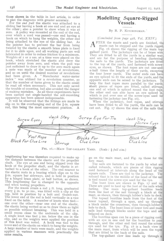
158 The Model Engineer and Electrician. those shown in the table in last article, in order to plot the diagrams with greater accuracy. For the end pull the elastic was attached to a sliding bar having a hook at one end and an eye at Modelling Square-Rigged Vessels. the other; also a pointer to show when it was at zero. A pulley was mounted at the end of the rod, over which a cord was passed—one end having a hook on which to hang the weights, the other end being attached to the eye of the sliding bar. As By R. P. (Concluded from page 428, to Fool Rope the top of the yards, and fastened with screwThe foot ropes are cut one-and- eyes, as shown. a-half times the length of their yards, excepting the four lower yards. The outer ends can have an eye spliced to fit the ends of the yards, and the opposite ends can be seized to the jackstays. Toe keep the foot ropes more parallel to the yards, short pieces of ropes are fitted, called stirrups, one end of which is spliced round the foot rope, the other end can also have an eye spliced in. which is put over one of the screw-eyes used for fastening the jackstay (see Fig. 16). When the jackstays, foot ropes, and stirrups have been fitted to all the yards, the sails can be cut out. Fig. 17 shows the sizes of the sails that As all these experiments have al i Serew Eye for Tie lengthening bar was therefore required to make up the distance between the elastic and the propeller shaft. The eye at one end being slipped over the hook of the propeller shaft, and the elastic is attached to a hook at the other. The end nearest to the elastic rests in a bearing which slips on to the g-in. square bar sideways, and is held in position by a hinged brass plate, or half button, as shown. This lengthening bar is changed to the opposite end when testing propellers. For the tensile strain a rod 3 ft. long, graduated every } in. to 30 ins., was fitted with a clip at the held in position by a bolt and thumb-nut. The lower end of the rod is held vertically in a vice fixed on the table. A number of knots were tied— one over the other—near one end of the elastic, the elastic being wetted so as to draw them as tight as possible without breaking. This was held in a small recess close to the underside of the clip. A single knot was tied 3 ins. below the one in the clip, and as the weights were applied the position of this knot was noted. A hook was tied to the lower end of the elastic on which to hang the weights. A large number of tests were made, and the weights applied in various same results, manners crew Lyes with practically Bloch For Clue Lines Slirrup Fic, 16.—Main Top-GALLANT YARD. top, JVezck ee Blocks For Block For Clue Line the Vol. XXIV.) finished, the masts can be stepped and the yards rigged. Fig. 16 shows the rigging of the main topgallant yard. The jackstays can be of brass wire. They are fitted to all the yards in a similar way, and are for the purpose of bending (fastening) the sails to the yards. The jackstays are fitted been carried out single-handed the self-recording apparatus has been almost indispensable. It will be observed that the fittings are made to slip on to the overhanging end of the 3-in. square rod, this being the most convenient position. A Screw Eyes Kircuineman, * FTER the masts and yards are the pointer has to prevent the bar from being twisted by the elastic a smooth brass plate is fixed for it to slide upon, and all working parts are well lubricated in order to reduce friction to a minimum. Weights of 1 or 2 ozs. at a time were placed on the hook, which stretched the elastic and drew the pointer away from zero, and when the pull was just sufficient to draw it up to the zero mark again a note was made of the number of revolutions, and so on until the desired number of revolutions had been given. A ‘‘ Manchester water-meter index ’’ was utilised for a revolution counter, so that the number of turns given to the elastic could be read off when necessary. This not only saved the trouble of counting, but also avoided the danger of making mistakes. August 17, rgtt. | go (Scale: } full size.) on fore Cloe Line the mast. main mast, and Fig. 19 those for the The sails are fastened to the yards by what are called robands, which are pieces of thin rigging cord fastened at intervals along the head of the square sails. These are tied to the jackstay. The roband that is in the middle of the head of the sail is tied round the screw-eye used for the tye. The bunt lines are shown in Figs. 17 and 1@ These are used to haul up the foot of the sails whem: furling. The main top-gallant buntline leads from the foot of the sail through a block at the mast, as shown, then through lubber’s hole to deck. The topsail buntline leads from the foot of t lower topsail, through a span, and up through a block under the crosstrees, then through lubber’ hole to deck. The bunt lines of lower fore and mai sails lead through blocks under the tops and belayed on deck. The buntline span can be a piece of rigging cor with an eye in one end for the buntline to p through, and the other end tied round the scre eye used for the tye. Fig. 18 is a back view the main mast, from which will be seen the ro that are fitted to the back of the sails. The top-gallant clew line leads up through
‘1161 ‘LI ysn3ny ‘uRp]I}901q pus J99NISUy [OpoW PUL cc. ee OF MODEL BARQUE. (Scale: } full size.) Fic. 21.—GENERAL ARRANGEMENT P. KiTcHINGMAN. By R. 6S1 T
August 17, Igtt | “The Model Engineer and Electrician. 160 block at the top-gallant yardarm, through another block at about the middle of the yard, then down through lubber’s hole to deck. The top-gallant sheet leads through the upper topsail yardarm, then through a block at about the middle of the yard, and down through lubber’s hole to deck, The upper topsail does not clew up, so no clew line is fitted. The lower topsail yard has no lifts like the other yards, but a rope leading from the yardarm up through a block at the upper topsail yardarm, then through another block at about the middle of the yard, and from thence through lubber’s hole to deck. fastened to main yard, just outside topsail sheet blocks, then to deck. | A back view of the foremast is not given, — as the ropes lead in just the same way as for the main. Stirrups Foot Rope % Fd Foot Rope } as sy ! KR Hi Cross i Trees = == =. = op-gaslantl”\’ Sheet (Chair)\| Ss | === = v £ SN 3s iS rop se TopsSz// Sheet, “Cheiny °° ¢ o oy o Fic. 20.—SatLt PLAN FoR Mi1zzEN Mast. wok Fic. 18.—Back VIEw oF Main Mast, (Scale: 4 full size.) (Scale: 4 full size.) The lower topsail clew line goes through a block at the lower topsail yardarm, then through another block at about the middle of the yard, and down through lubber’s hole to deck. The clew garnets lead from the clews of mainsail up through blocks Shees| Sheer oy | | Fig. 20 shows the mizzen and mizzen topsail. The foot of the mizzen should not be laced to the boom. When you want to furl one of the square sails, slack off the sheet and haul on bunt lines and clew
The ‘Model Engineer and Electrician. August 17, Igtt. y up and lash it to the vard, lines, then roll it neatl 4th, as shown in photos Fig. 12 and 13, M.E., May ToL. set. The rigFig. 21 snows the barque with sail lit tle different ging of a ship or brig, etc., is so 16t foremast the side of the yard the brace leads from arm, the at k bloc the ugh thro ees le-tr trest d to the aftermost then through a_ block seize topsail braces lead from foremast shrouds.throThe ugh the block at the yardarm, the foremast cap ———a A aa ss S aN Bunthines Buntlines Fic. 19.—FrontT VIEW OF FOREMAST. (Scale: 4 full size.) ption of the one from a barque that the descri braces will serve equally well for the othe r. The of brigs, and on the ef the yards on the main mastforwa rd. The blocks eizzen mast of ships, lead _ are on the fore side of the main yar d in brigs, and . Fic. 17.—Front VIEW OF Matin Mast cap, then through a block fastened to the fore through lubber’s hole to deck. s lead from the yardarm The top-gallant brace crosstrees, then through the r unde s block ugh thro lubber’s hole to deck.


