- The “Bent Frame” Innovation. Kitchingman’s approach moved away from the traditional “upside-down on a plank” method, which he criticized for requiring perfectly trued building boards that few amateurs possess. Instead, he utilized a temporary internal guide piece (44.5 inches long) to support the stem, keel, and stern while the hull was planked. Once the exterior shell was complete, the builder would steam and bend elm frames directly into the hull, ensuring a natural, stress-free shape.
- The Art of Steaming Timbers. The second part of the series (January 16) dives into the delicate process of steaming elm timbers (1/4-inch by 1/8-inch).

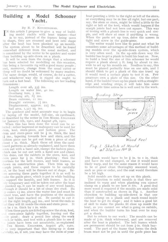
Januaty 9, ig9t3. Building a The Model Engineer and Electrician. Model Yacht. By R. P. Schooner is to say, instead of the frames being sawn to shape, they are steamed and bent into shape after the boat has been planked up on moulds. The system about to be described will be found different from the usual method, boat pointing a little to the right or left of the stern, or everything may be in line all right; but one part, say, the stem or stern, might be tilted a little to the right or left of the keel, which would happen if the scarph joints had not been cut square. This way KircHInGman, [* this article I propose to give a way of building model yachts with bent frames—that somewhat 35 and is considered by the writer to be quicker and easier than building up-side-down on a plank. It will be seen from the design that a schooner has been selected for modelling on this occasion, this being a favourite rig with a good many people ; and, moreover, change from the usual cutter or sloop will no doubt be welcomed by many readers. lhe same design ,would, of course, do for a cutter, and whichever way she is rigged she ought to turn out a fast boat. The following are her leading dimensions : Length over all, 53% ins. Length on water line, 40 ins. Overhang fore, 5 ins. Overhang aft, 83 ins. Beam extreme, I1 ins. Draught extreme, 7} ins. Displacement, approx. 225 Ibs. Sail area, 1,327 sq. ins. The quickest and most accurate way is to begin by laying off the model, full-size, on cardboard, as described by the writer in THE MoDEL ENGINEER for January 6th, 1910, and August 4th, rgro. When this has been done the wood can be selected: either baywood or mahogany can be used for stem, keel, stern-piece, and fashion piece. The stem and stern-piece will be § in. thick, the keel 3% ins., tapering towards bow and stern, and the ‘ashion piece can be got out from a piece of stuff .bout 1 in, thick. Mark these off from the cardnoard patterns as already explained, and have them sawn out with a band saw, except the fashion piece. vhich can be cut out with a hand saw and chisel. Chis done, cut the rabbets in the stern, keel, and stern piece for % in. thick planking; then the nortises for the belt frames, and bent frames, as shown on construction plan. Then trim up the scarph joints, and these require to be carefully it, or the boat will be thrown out of shape. Be- ‘re screwing these parts together it is as well to iake the guide piece, which is put in while building ) support the moulds, and belt frames. As it is ily temporary and will be taken out after the boat planked up, it can be made of any wood handy, \though it should be a bit of clean dry stuff. Its :p comes 1} ins. above the water line and must be aned true, and have the positions of the moulds d belt frames marked on. Be careful to cut it ist the right length, 44} ins., and bevel the ends so “nat they will fit inside the stem and stern piece. It n be 1 in. thick by 1 in. wide. \Vhen these parts are fitted up screw the stem, keel, id stern-piece lightly together, leaving out the le piece; draw a pencil line along the work nch or table, and test with a plumb line to see if – joints have been cut accurately, as explained THE MopEL ENGINEER, August 4th, IgIo. is very important that this lining-up is done .cefully, as, if not, you may have the stem of your of testing with a plumb line is very quick and ple, and will show at once if anything is sim- wrong. When the parts set up true, drive the screws in tight and screw in the guide-piece. The writer would here like to point out what he considers some advantages of this method of building models over the up-side-down system, which is very often used. In the up-side-down way the builder has to get a plank to build his boat on. Now, to build a boat the size of this schooner he would require a plank about 5 ft. long by about 12 ins. wide to set up his moulds on. Needless to say, this must be planed perfectly true on one side, and I should think to get a plank of this size trued up it would need a surface plate to test it on. Few amateurs own a plate of this size. On the other hand, if the builder trues up his plank with a straightedge and winding strips, it will take him some considerable time unless he is well used to the work. Binding Slrip WDVDO6O6> aS) Wood Keel Fig.l Sketch of Mould al Slzlion NP 9. The plank would have to be ¢ in. to 1 in. thick and have its end clamped, or else it would most likely warp, and for the same reason it would have to be of good clean thoroughly seasoned wood, such as pine or cedar, and the cost would therefore be a bit high. Solid moulds are then set up on this plank. The objection to solid moulds is that they are inclined to warp and when planking you cannot clamp on a plank to see how it fits. A good deal more wood is required if the moulds are made solid than if constructed as shown in Fig. 1. Another objection to building up-side-down is that one cannot clamp on a plank and mark round inside the boat to get its shape; and it takes a good bit of skill to make the planks fit close up inside the boat, as you cannot see what is going on outside, and when the builder turns his boat over he may get a shock. But to return to our work: The moulds can be made of j-in. thick whitewood, and are removed after the boat is planked. The belt frames which are permanent should be cut from }-in. thick bay- wood. The part of the frame that forms the deck beam must not be put in until the guide piece has
36 The Model Engineer and Electrician, January 9, 1913. PDP — – -j- —- ~ YM Sj Sheer Plan 6° 4 See Cnene E _— Half Breadth Plzr SHEER, HALF BREADTH, AND BODY PLA?
7 January 9, ij – IR ee . a 1913. The is po Model /4. TT Lead| Kee pil| Fibs ‘2 oy 15 By R. P. om TT a | Engineer 18 Ins KITCHINGMAN, and Electrician. /6 im 1? mee /8 poses /9
i January 16, 1913. of chalk or pencil. Then prepare the bent frames, these are }-in. sided by }-in. moulded, and should be cut a little longer than is actually required. They should be of good sound elm and it is better Building a Model Schooner Yacht. to cut a few extra ones in case of breakages. The timbers will now have to be steamed and this requires care, as,if they are not steamed enough, they will break when being bent into position, and By R. P. KITCHINGMAN. (Continued from page 38.) the first plank on each side is fitted FTER and A the next one can be cut out rough it fits. if steamed too much they become brittle and will not bend nicely. held on with clamps to see how Let it overlap the plank first put on, then Few model yacht builders care to go to the trouble of making a steam box to steam their timbers in, and I believe a good many boil them in water. -un a pencil line along inside the boat, remove the plank and saw out to the line, and after a 10 59 The Model Engineer and Electrician. 10 5 Ss jag’ 30 Ins. 25 20 25° 186 Sg.lns. y Tole! Sal Aree 2 ue 6 Sols 118 ae ” 1327 Sq Ins . fie Ca pt Zi if 62″ 261 Sq Ins 5 120.59 Ins ug” |] 1 I 128 Sg/ns 530 Sq ins \ Ly \ Wag LI +14″ Kime 31k” ‘ 2 | it SatL PLAN FOR A MODEL SCHOONER YACHT. ottle more trimming it should fit all right. Be sure ne edges of the planks fit up close inside the yacht _s well as outside. This boat will require eight >lanks each side, so divide mould No.9. into eight parts, also the bow and stern into the same number, -his will give a guide as to the width of the planks. When planking carry both sides of the boat up cogether, and of course, when the battens that were put round to steady the frames and moulds .ce reached they must be removed. When fitting :he top planks remember that they must be removed iter the timbers have been steamed in, so as to =t the inwales. When the planking is finished the next thing to ‘5 is to steam the timbers. These are put in at she same place as the moulds and also one between .ch mould fas shown on construction plan. Mark sheir positions between the moulds with a piece I advise the reader tu have a quiet hunt round the kitchen and see if he can find an ordinary household steamer, the sort of tin affair that fits on to the top of a saucepan and is used for steaming potatoes and the like. If he can capture one of these he will have an excellent steam box, for all he has to do is to fill up the saucepan with water, place it on a fire or gas stove, put the steamer on top of the saucepan, and when the water begins to boil put the timbers into the steamer, pop on the lid and wait for the timbers getting cooked. If “ the good lady of the house ’’ comes and catches you in the act, don’t say THE MoDEL ENGINEER put you up to the dodge, as that would not be fair to the Editor or writer of the article. When you think the timbers have been steamed enough, take one out and try it to see if it will bend if so, you can to the shape of the boat nicely ; and
00 The Model Engineer and Electrician, January 16, 1913. ee = c – p g gt = apt Bent trame(El m) £’sidea Ra ew >. eee a «*-r-EXN nn..-—2=az<—w .-—] k moulded. Be/f treame Sw To shape CONSTRUCTION PLAN OF MODEL
Januaty 16, toi3. The Model Engineer and Electrician. bi i it Slern piece ¥" thick Heels reduced lo i tor mortise ¥ Belt Frame : GY e/t frame Belt frame sawn lo shape Deck Supporly N?/0
342 The Model spark at present than it gave at first ? Engineer (2) If the coil gives a 2-in. spark without a condense r, what should be the length of the spark it would give with a suitable condenser ? (t) It rather looks as if condenser is going wrong, though we would suggest that the fault may be with your battery. (2) We cannot say, but the condenser usually makes a very great difference ; we should expect the coil to give easily }-in. spark, if not more, when condenser is puton. Try another condenser, and attend to the battery. [3051] The Study of Yacht Designing. A. H. G. (Cromer) writes: I have just been apprenti ced to a “ Boat, Small Yacht and Launch ” builder, to learn that trade. I am sixteen years of age, and having received a very good education intend to go in for designing. Beside the usual Grammar and April 10, Electrician, 1913. and try all you know to trace the cause of the want of success. One great difficulty in boating matters is the ‘‘ human element ”’ or, as it is sometimes called, the “ personal factor.” We have seen two men sailing alternately in two boats and one man won nine times out of ten and yet they were both experienced yachtsmen—and if anythin g the winner had less experience than the loser. You can sometimes gather useful information from records in the yachting periodicals, particularly if you can get some old hand to explain matters to you. We think you would do better (unless you have had a great deal of experience in sailing a3 well as rigging School lessons, I have learned mechani cal and machine drawing, graphic statics, and have gone a little way into mechanics, apart from the mechan- ical drawing. I wish to ask you if you could name FIQR any periodical or periodicals, dealing with both the practical part and the designing. Also could you name any books on the subject of designing. I intend building a model schooner, having been much struck with the description of Prospero, in your issue of 26th September, 1912. I have built two other boats, but now have more ideas on the subject, especially since I have been to work, which is only just over a month. (rt) I know very little at present, however, about design, so I am writing to ask you if you think this outline, Fig. 1, suitable. It is taken from your Practical Manual, No. 4. (2) I see that the keel of the 36-rater design is built down as in Fig. 2 (see part enclosed by rectangle), whereas, in design for 1o-rater, it is not built down to, but keel is fixed on afterwards, Fig. 3. I have read chapter on Rating carefully, but do not quite see the advantage of building down to keel. Could you kindly explain this ? There is very little published concerning the class of craft you mention that is of any practical use. Most yacht designers are very reticent about their boats for two reasons; first, their clients do not wish to have their craft copied by all and sundry ; Fig 3 and building boats) to rig your boat as a sloop or cutter especially as the sketch you refer to is designed for that (Fig.1). Your sketch has the counter cocked up too much which would cause a drag in the water if it ever got into it. If you turn to page 37, you will see that Fig. 26 has a much finer counter than B or your sketch. (2) If you read Chapter II of the manual again you will see the rea- son for this. The boat with the wedge-shaped keel is built for the Y.R.A. rule, which penalises the difference between ‘skin girth” and “chain girth’ very heavily, and this shape reduces that difference considerably, This rule is no longer in force, but another equally taxing this difference now obtains (see recent articles by Messrs. Kitchingman and Delves-Broughton). [3,657] Making Small Electric Motor. J. 1. C. (Edinburgh) writes : I give a sketch of a small electric motor which I propose.to make. Is this design efficient ? The field-magnets are of softiron bar, welded. The bearings are solid brass rod bored out, with lubricators, and the base is 3-32nds in. brass plate. I have no lathe and but a small workshop with a few necessary metal-wo rk such as taps, dies, etc., NN? 3057 Fegs and, secondly, it would not pay them to give the world the experience they have gained by infinite pains and study. The only thing to be done is to observe carefully the lines of every boat you come across and compare their lines and performances, and collect all reasons for the better or worse behaviour. A great deal of information can be obtained from Fronds’ (elder and younger) books on naval architecture, etc. ; but the information in them is the of little use without a vast amount of experience and observation, as there are so many factors involved and so many conditions to be conformed to that the best must of necessity be far from perfect in all mind winds and weathers. You should bear in that very often more inform ation is to be gained from a failure than from a success, so remember to include in your tabula ted record all failures, tools, so I had to devise a way of building the armature stampings on to the shaft. I sweated a piece of brass tubing, 5-16ths in. diameter, on to the 3-16ths in. shaft and soldered a brass disc, rin. x }in., on one end, and tapped the other for bolt. I shall do the same for commutator. Do you approve of this? Kindly answer the following questions. (1) If this motor (sketch enclosed) consumes 18 watts, would it give that output working as a dynamo; would main it give? continuous if not, how much (2) I have here the 230-volt current, and wish to drive the motor from it, how few 16 c.-p. carbon lamps in series must I use? passes :23 ‘40 amp. amp (3) If one of the above lamps would two of them in series pass If so, must I add lamps till I get the amps. the motor consumes. If this motor consumes 18 watts, should I wind it for 18 volts 1 amp., and use 5 of the 16 c.-p. lamps topass1-ramp? Please tell me how much wire and of what gauge do I require to wind the motor, and use the smallest number of lamps. I propose to fit 8-pole cogged- drum armature wound on to a 4-pole commutat or. Is this the best winding for a beginner? It is the
Model Engineer And Kilectrician. A JOURNAL OF PRACTICAL MECHANICS AND ELECTRICITY. EDITED BY PERCIVAL MARSHALL, A.I.MEcu.E. VoL. XXIX. No. 636 JULY 3, 1913. PUBLISHED WEEKLY. Two Notable Yachts. O those model yachtsmen interested in the International Rule of rating the designs of Minerva and Substitute, apart from their being first and second respectively in the M.Y.R.A. National Championship, 1913, will be of more than their arrangement of centres, but compare the physical advantages that one may have over the other. Although interest, inasmuch as they differ in type bout as greatly as two boats under the same rule could be made to do so and be all-round performers. As the present interest is of type and not of lines st will be seen that by a proper choice of dimension and by allotiing correct amounts to each factor of the formula, you can obtain a boat of light or heavy lisplacement, or deep or shallow body, and not enly conform to the rating rule, but produce models that compare equally in size; that is, the size of factors of speed, which are sailing length, sail, and the power to carry it. It will be seen that Minerva pays a large 3d tax compared with Substitute, which has been borrowed from the sail factor and load water-line factor. As both boats are balanced there is no need to discuss has a shorter sailing she has a longer water-line than Substitute when heeled, and less bulk to drive Two Views oF * MINERVA” ON THE erdinary Minerva length when upright, RiIvER Léa. being 20 per cent. lighter displacement. The beam of each being equal, their power can be compared from their respective keel weights and distances between the centre of gravity of same and centre of buoyancy. Swhstitute has the greater amount of lead, but although Minerva’s centre of gravity of keel is about the same distance below the water line, her centre of buoyancy is much higher, greatly increasing her artificial stability. Although Substitute is allowed a much larger sail area than that of Minerva, she has been found to do best with about the same amount. This is not through inability to carry it so much as it being more than is required to give her her maximum speed in average conditions ; it consequently expends itself in driving the hull to leeward.
The Model Engineer and Electrician. 4 How Sheet Metal is Sold. ; I shall now.explain the various gauges, or thicknesses,. by which the different sheet metals and wires are sold, so that the reader, on going into a metal warehouse, or ordering anything by post, can get what he requires. The system that is in use at the present time, of denominating the thickness of different sheet metals is much more com- plicated than some would think, and, personally, I should not advise the average amateur to bother with it at all, but to adopt a much simpler method, July 3, 1913. gauge or happen to have a piece of metal by him of the required thickness to use as a pattern, the simplest way is to take a piece of wire somewhat thicker than is required, and file a small flat on opposite sides at one end. These need only be } in. long, as this is quite enough for the assistant at the metal warehouse to apply the gauge to. Sheet brass in the flat—that which I shall explain later. The gauge now used in the trade is called the Imperial Standard Wire Gauge. It is also sometimes called the British Standard Wire Gauge, and is used for sheet metal as well as wire. These gauges take the form of a circular or oblong steel plate with rounded ends. Round the edge they have, as a rule, 36 openings, into which the metal or wire that is being gauged is placed. The largest opening is marked 1, and is equal to 5-16ths in. The opening marked 36 is about equal to 7-1,000ths in., and the other openings are graduated between the two. These gauges cost from 7s. to 10s. each. Now, many amateurs would not care to spend this amount on a thing that they did not perhaps use once a month, and then again these gauges are only for sheet brass, iron, and steel. Sheet zinc is sold by a different gauge, and sheet tin is not sold by gauge at all. This is really iron or stee] plate coated with melted tin, which forms a thickened edge that prevents a gauge being Sait PLan or “SuBSTITUTE.” (See page 1.) ts to say, not coiled round in the form of a drum— can be bought as thin as No. 33 Standard gauge,- it is much less and up to 4 in. thick. Of course, trouble to flatten than the other kind. It can be had hard or soft (the price is the same), and the former is much stiffer than the latter, and therefore need not be so thick. Sheet zinc is sold by the following gauge, which runs from No. 4 to No. 20. No. 4 is equal to No. 33 of the Standard; and No. 20 Zinc gauge to No. 16 Standard, and as I before remarked, as the divisions on the latter are somewhere near the divisions on a rule, an idea can thus be formed by comparison of the numbers of the two gauges of the thickness of the zinc gauge. Tin plates are sold by a variety of names and marks that are rather puzzling, because they denote different thicknesses with different sizes of sheets. To give the full details would occupy too much space, but, roughly speaking. the thinnest tin is known as tagger and is about No. 36 Standard Gauge, then comes I.C., which ina plate of 20 x 14 is about 30 Standard, and then it isknown by X’s, SaIL PLAN oF “MINERVA.” applied. (See page 1.) It is sold by marks known as crosses, which I shall explain later, as well as the gauge by which zinc is sold. If the reader does not possess a standard gauge, and wishes to buy some sheet brass, iron, or steel, it should be remembered, with the exceptions of the openings marked 1, 2, and 3, the others bear some resemblance to the ordinary divisions on a rule. Thus No. 4 is } in., No. 10 about 1-10th, No. 16 1-16th, and so on. If a very exact thickness of sheet metal or wire is required, and the reader does not possess a or crosses, as they are termed, one x being about 30 Standard, up to six crosses, which is about 21 : Standard. Tin is sold in sheets that run from 14 X Io Ins. to 20 X 14 and 25 X 17. lf tin is required to be bent both ways of the sheet—say, for instance, in making a tray or dish— charcoal plate should be asked for, as the common quality, or coke plate, has a strong grain in it and will break if bent this way. Sheet copper is sold by the same gauge as brass, and can be obtained hard or soft and in the coil or flat. Sheet brass is somewhere about tod. per Ib.. and sheet copper about Is.
: July 3, 1913. The Model Engineer and Electrician. Minerva by reason of her shape, has more grip upon the water, and is much more under control before the wind. Therefore, the only real disadvantage that Minerva suffers is shorter length when upright, Model Engineering. By Owew LINLEyY. ANY amateurs suffer from ignorance on this point, and it is no uncommon sight to see one spending an hour or so making some- thing that he could have bought for a penny or two, or wasting his time straightening wire when it G4 cee. against which her advantages are: Less initial stability and greater maximum stability; greater sailing length when heeled; lighter displacement, with a consequently finer displacement curve. While Substitute should hold Minerva on a reach in moderate breezes, the latter should be easily her superior in beating or running under any conditions Buying Raw Materials for fo —— 2 Bopy PLAN OF *«¢ MINERVA.” (Scale: 4 full size.) of wind or water, but being a more delicate boat to handle, would sacrifice a great deal of speed if not sailed up to top notch, a very slight alteration can be bought already straight, if he only knew it, or trying to bend sheet-metal that is not intended making all the difference, while the performance of Substitute is more stolid. In going into a metal warehouse or large tool dealer’s, or ordering anything by letter, if living for that purpose.
The Mode! Engineer and Electrician. July 3, 1913. in an out-of-the-way place, it is often difficult to get what is wanted, even if the reader is aware of its existence, unless he knows the term which it is known by in the trade. It is often useless to describe the material that is required by its properties, as the assistants in these places do not, as a rule, know anything to speak of concerning the use of the materials, etc., that they handle. To take one instance only—that of sheet brass, which is a metal much used in model work. 3 dipping metal, and is almost as soft as lead. -It is very easily cut with a piercing-saw, and bent or folded into various forms, and, amongst other purposes, is used for covering fenders and parts of harness, as in the thinner gauges it can. be rubbed down. with a burnisher so as to take the shape of anything under it. Sheet brass is mostly sold in coils, and it is not generally known that it can be also obtained in the flat, which in some cases is a great saving of SAAT a4 Oe tl oe sea yar er a dian oe Fee mae es ca ee eee een anaes e en o — 1 For description] 1 1 r 1 in L 1 4 —_ SHEER, HALF BREADTH, AND BoDy PLANS OF SUBSTITUTE. Many persons know that there are hard and soft of this, but they do not know that an The former is called gilding metal, and is almost as stiff varieties extra hard and soft quality can be obtained. as steel, and is useful for springs and other purposes where, for certain reasons, the latter metal cannot be used. The other variety is called n 1 4 [see page I. time. The same applies to wire, which is mostly sold in coils or rings, as they are termed, and which is troublesome to straighten. If straight wire is required, it can be bought in several varieties. I shall describe, under different headings, how the various sheet metals, wire, tubes, and other materials are sold, and where they can be obtained.
The Model Engineer and Electrician. August 28, 1913. 203 i 4G = half girth. Model Yacht Racing. /S.A. = one-third the square root of the sail area. The product of above being divided by 2 to give The 80-Centimetre Rule. rating. By Epwarp W. Hopss, A.I.N.A. The dimensions all being taken in centimetres— of course, if preferred, the dimensions may be resolved into inches—but the metric system is so easy to use that its adoption has much to recommend it. The details of the formula are ascer- HE 80-cm. Continental Rule for International and Inter-Club sailing has been introduced into England by the Model Yacht Racing Association to provide a rating rule that should prove of great benefit to model yachting, as although intended primarily to enable the Continental and British Clubs to compete on an equality tained as follows :— L = Actual length of water line, taken at the water level, as in Fig. 1 at L, the ship as regards type and size of boat, the adoption of being rigged and sails set. B = Width of beam measured where it is this rule for inter-club sailing has much in its Fic. 9.—AN 80-c.m RacinG YACHT, BUILT TO THE 80 C.M. RULE. designer. The formula is— L+B+4G 4+ 3d+4V75.A. 2 L = load water line. B = greatest beam. = 80 cm. the largest taken by measuring between vertical lines drawn down from widest part and measured at deck, as B, in Fig. 2. 7) ro favour. In the first place, the boats are lighter and smaller than the 12-metre or 1o-raters, and therefore transit is easier and more practical, while at the same time the boats themselves are of sufficient size to warrant their use by experienced model yachtsmen. The rating formula is somewhat similar to the International Rule for 12-metre models, with the important omissions of the overhang taxes at bow and stern, thus giving greater flexibility to the Half girth, measured with a steel tape at the greatest station wherever found, the chain girth from covering board to The covering board being measured. freeboard on each side of the hull at this station being deducted from the girth measurement. The result divided by 2 giving the half girth (4G) of the formula. The girth station to be not less than +55aftof the forward end of the waterline. Note.—There is no allowance of an
204 August 28, 1913. The Model Engineer and Electrician. in square terms, of the area as rigged. The actual sail area being measured for the purposes of this rating rule, all curved edges being taken to be straight lines, thus a convex edge would give a few extra square centimetres of sail area, over the rated amount, a concave edge the reverse, by losing a little under the rated amount. extra 3 per cent. for drop in keel as in the International Rule. The $G mea- surement being taken where the skin girth is the smallest when the measure of several chain girth stations gives the same result. Fig. 3 shows the method of measuring The to ascertain }G measurement. chain girth being found by measuring _ ; SS ee t H 1 Z.W.k i \ Frat WATER LINE MEASUREMENT. from coverboard, or top of deck where no coverboard used, at A, straight around the hull C to coverboard, or deck top, at B. Deduct freeboard F and freeboard F’, then divide by 2 = 3 girth, freeboard being measured from coverboard—or deck top—to actual water level, at the same station. The product found by adding the together is divided by 2 to give rating. foregoing Fig. 5 shows two different mainsails both rating as the same area. The length of the straight line L being used for the purposes of the rule. The chief features to note in the above formula are that the actual length of the water line is taken, bow and stern taxes are neglected and there is no allowance of 3 per cent. for drop in the keel. The method of measuring the sails of an 80 cm. model is as follows :— Surface AREA 4 /S.A. = 4 of the square root of the sail area. The measurement taken, and expressed Mainsails—Length AC (Fig. 6) MEASUREMENT OF MAINSAIL. OF SAILS. 3d == Three times the difference between the chain girth (as above) and the skin girth, measured by stretching a steel tape and following the shape closely, at the same section as the chain girth, and at the 4G station. Fig. 4 shows the difference, the skin girth being indicated by the thick black line, chain girth shown dotted. of multiplied by height a, add length A B multiplied by height b, the total to be divided by 2, giving the surface measurement. Surface of Foresail.—Length E G (Fig. 6) multiplied by length C, the result being divided by 2. Surface of Topsail—Length L J (Fig. 6) multiplied by height e, and length LH, multiplied by height d, the total being divided by 2, giving the surface. For the purpose of this rule the sails are measured from the points of the sails where the eyelet is inserted, as in Fig. 7 at E.
The Model Engineer and Electrician. August 28, igi3. It is interesting to notice that this rule has been in use on the Continent for the past six or seven years, and has proved quite satisfactory, and it is hoped that the British boats in the team sailing for the International Cup in September of this year will put up a good fight and be successful in winning the International Trophy offered by the Model In the case of the sail fastened under or behind a spar, the part hidden is not taken count of when The surface exposed as in Fig. 8, measuring. A, B, C, being measured only. In measuring the models for the purpose of the 80 cm. rating, it will be noticed that the actual surface of the sails are measured, and not as in the International Rule, where the area of the mainsail and top sails are added to the area of the fore- Yacht Racing Association. Already in England a number of boats have been built to this rule, notably, by members of the “ Solent ’ Model Yacht Club, and excellent racing triangle. As the total sail area must be measured when the boat is rigged it follows that a spinnaker is to be had with these models. In conclusion, the writer hopes that those who build to this rule will have good sport and fine sailing with their boats, and he also wishes to express his gratitude and high appreciation of the unvarying courtesy and helpfulness of Mons. L. Cazenove, of the Model Yacht Club, Paris, for his kindness in supplying much information for the preparation of this article and in organising the International Model Yachting Regattas. cannot exceed the area of the foresail, and when Ms A Fa ¢c } Fia.7 205 Fic.8 MEASURING THE SAILS. Steel the spinnaker is used, the foresail must be removed ; or be used as the spinnaker. The following measurements are typical of an 80 cm. model :— B= 24cm. L, = 8riem. 3a = 3G = 23°5 3 44/S.Av = 27 or, expressed in the terms of the formula— 81 + 24 + 235 + 3 + 27 _ 1325 = 79°25 rating. 2 And it will be seen from the photograph (Fig. 9) that a wholesome type of boat can be produced under the rule, the boats are fast, seaworthy and steady sailers. The abolition of the bow and stern taxes simplify the rule, while the retention of the | | | for Magnets. CONSIDERABLE time and effort are wasted, says a writer in The American Machinist, in making worthless permanent magnets, from lack of a very little modern information. Ancient superstition dies hard. For example, German silver is still called for by amateurs and some engineers and is regularly sold and used as a resistance material. Correspondingly, in a recent specification for magnet steel, carbon steel was seriously recommended. The truth about permanent magnets is that the best tool steel is the worst material to enter into their manufacture. Some inferior grades of carbon steel will often make a better permanent magnet. Tungsten steel, however, is so far superior that


