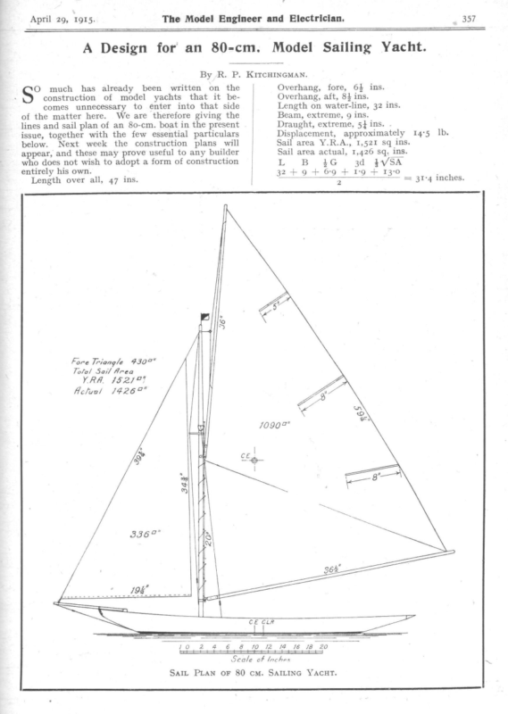
- The 80-cm. Model Yacht (R. P. Kitchingman). The April 29 and May 6 issues detailed a high-performance model yacht designed for the 80-cm class. Kitchingman emphasized that while much had been written on general construction, his focus was providing a refined set of lines for builders seeking a competitive edge.
- Specifications:
- Dimensions: Length over all (LOA) is 47 inches, with a waterline length (LWL) of 32 inches. It features an extreme beam of 9 inches and a draught of 5.5 inches.
- Displacement: Approximately 14.5 lbs.
- Sail Area: The actual sail area is 1,426 sq. ins., while the Y.R.A. rating measurement is 1,521 sq. ins.
- Technical Plans: The publication provided a full Sheer Plan, Half-Breadth Plan, and Body Plan to define the hull’s curvature. Subsequent issues included Construction Plans, detailing “Sawn Frames” (A) and “Bent Frames” (B) to assist builders in assembling the skeleton of the vessel.
- Specifications:
- Principles of Yacht Design (W. J. Daniels). Writing in September 1915, W. J. Daniels explored the “Geometrical and Mathematical aspects” of design, using his yacht Onward as a case study.
- The Three Pillars of Design: Daniels explained that a hull is represented by three sets of lines: the Body Plan (cross-sections), the Water Line Plan, and the Buttock Line Elevation. He noted a fundamental rule of naval drafting: any line that appears as a curve in one plan must be a straight line in the other two.
- Design Workflow:
- Midship Section: The starting point, governed by the specific rating rule the boat must conform to.
- The Deck Line: Drawn to determine the beam and curvature; Daniels suggested that for symmetry and balance, the breadths should correspond around the point of maximum beam.
- The Bilge Curve: A critical longitudinal line passing through the “turn” of the hull from the topsides to the underbody (the “floor”).
- Freeboard & Sheer: Daniels noted that while it might seem logical to have the highest freeboard amidships to keep water out, the forward motion of a yacht creates a “trough” in the water, allowing for a lower freeboard in the center for better aesthetics without sacrificing dryness.

April 29, A Design for an 80-cm. By R. P. much has already been written on the construction of model yachts that it becomes unnecessary to enter into that side of the matter here. We are therefore giving the lines and sail plan of an 80-cm. boat in the present issue, together with the few essential particulars below. Next week the construction plans will appear, and these may prove useful to any builder who does not wish to adopt a form of construction O entirely his own. Fore Triangle Model Sailing Yacht. KITCHINGMAN. Overhang, fore, 64 ins. Overhang, aft, 84 ins. Length on water-line, 32 ins. Beam, extreme, g ins. Draught, extreme, 5} ins. – Displacement, approximately 14°5 Sail area Y.R.A., 1,521 sq ins. L B 3d 4G. 2 4307 Total Sail Area (827°) 14267″ 6 10,2,4 Ib. Sail area actual, 1,426 sq. ins. 4VSA 32 +9 + 69 + I’9 + 13’0 Length over all, 47 ins. YRA. Aclual 357 The Model Engineer and Electrician. 1915. 1416 18 20 Scale of Inches Salt PLAN oF 80 cm. SAILING YACHT. = 31-4 inches.
358 The Model Engineer and Electrician. Halt Breadth Plan. April 29, 1915.
April 29, 1915. =n The Model Engineer and Electrician. 359 ee eee 77. Be =i Scale for Sheer + Halt Breadth Plans 23.4 5 6 7 8 3 4 5 a T 1 i I DESIGN 9 10 1 12 Ins. It i a Scale for Body Plan, SS | 1 7 6 FOR AN 80 CENTIMETRE SAILING YACHT. BY R. P. KITCHINGMAN. 8 Ins. a ; SHEER, HALF-BREADTH, PLANS. a _ SSS = – == eee aS 2 = ee L ee _ les oe NI] 7 7 e Ne ee e 7 q AND BODY
380 The Model Engineer and Electrician. May 6, tots. “ Mast ¥ Diam A= Sawn Frames. 8=Benrt Frames. Br Top of Lead Kee/ 6 Heads of Bent, Frames Heads of _ Sawn Frames | CONSTRUCTION PLANS AND DETAILS FOR AN [For Sheer, Half-Breadth, Body, 7 | {
[‘anssz ysvy aas ‘sunjg 1s pun *‘NVWONIHOIIY ‘qd ‘WY Ag ‘“LHOVA ONITIVS ‘WO 08 [ay fo ul Uy LlO/y Bx B Vi iy sawd/y | 7 b/ D (Er °any fP9YSHOUIsahE/ 1gt 7 ch LL el IL [22 POOM £0 wos/Og a UBINIIWDE;q pue sseulsuq [OPOW PUL ey 6 /aay poo S161 ‘g Avy
The Model 244 Engineer Model Yacht Designing. By W. J. Danie.s. | and Electrician. September 16, 1915. a K NX }ee Q Geometrical. N the article on Onward to-rater in September 12th, 1914, issue, it was stated that the position of centre of buoyancy was calculated for several different angles of heeling. That the reader may realise the necessity for this it is essential that he shall understand the elements of yacht design, both from the geometrical and also mathemetical aspects. The hull of a yacht is represented by three sets || x of lines, which are known as the cross-section or body plan, water line plan, and buttock line elevation. Any line that is a curve in one plan is always a straight line in the other two. If the intersection of these lines coincide in all mines the beam and Tealest Peplh of Actual 2Bo Aig ane be governed by the rating rule to which the boat is to conform. This section at once deter- depth of body of the hull, c, Fig. 1. The length of the load water line will determine the angle that the profile makes at each end of the water line with the latter. It is the endeavour of every designer to get this angle of entrance and delivery as low as possible, but this must not be pushed to such excess as will give too sharp a turn in the region of the mid-section. Cc The deck line, D, D, D, should now be drawn, and for reasons explained later should be corre- sponding in breadths and curvature either side of the point of greatest beam. Your deck line will bilge at right angles to a tangent, +, x, to the latter froma point on the midship line. ‘This diagonal gives you the height of the profile line on the stem, but does not give you the fore and aft position of the profile where this is the height. To obtain this you must now draw the bilge curve in plan. First, divide the midship line into an even nurthber of equal parts between the water line ends (ten divisions will be found very convenient spacing) and draw lines at right angles out to the deck line representing the positions of the cross section at these spaces, and also at similar spaces outside the region of the load water line. Repeat your midships section on the opposite side in the body plan, and taking the width of deck at the extreme end of the counter and also the distance above the water line as indicated by the height to which your profile has risen, at this point draw a tentative transom section. You now have the height of the freeboard amidships and at the transom, so that by deciding on the height of the freeboard at the stem head we now have three points through which to draw our deck sheer line, G, G, G, Fig. 2. On paper it would appear that in a sailing yacht that is to heel over the greatest freeboard should, in order that the water shall not get on deck, be at its highest amidships. Fortunately, however, for the sake of appearance the forward motion of the yacht causes a trough to form in which the bine of the sections at each end of the load water line. ; Across the mid-section draw a diagonal, E, E, Fig. 2. This is a line that should pass through the “fe 2h. of @ Gre determine the beam Fic. unfair. The designer starts off by drawing a midship section, a, a, a, Fig. 1, the shape of which will I.—FIRST STAGE IN DESIGNING THE HULL Form. these drawings the shape of the hull must of necessity be fair in curvature, 7.¢., free from bumps, always, of course, providing the curves in the plans are not
The bilge curve is firstly drawn as it would be seen in plan if looked at from a point at right angles to its own plane. This curve is drawn using the midship lines in the deck plan as a base line, but on the opposite side to the deck curve. With your dividers transfer from the body plan the length of the diagonal from the midship line to the bilge, and mark this measurement off _ opposite the half breadth of the deck plan on the line representing the amidship section. You now draw the diagonal on the other side of the cross-section plan, from the same relative spot on the opposite side at the midsection to the turn in the You then measure transom section. off up this diagonal to find a spot the same distance away from the midsection as the distance from the section to the amidship line on the opposite side. From the point found in this manner measure the distance to the | [| Tue BILGE CURVE DRAWN IN, AND ALSO TENTATIVE Bow AND STERN SECTIONS AT EACH END OF THE LOAD WATER LINE. part of the section between the bilge and the reverse-turn into the keel, or fin, is known as the floor of the vessel. View of Bilge Curve in ifs_own Plane midship section and deck plan. The bilge curve is a longitudinal line, E, E, Fig. 2, drawn throughout the length of the hull, passing through all the cross-sections at the point where the turn takes place from the top sides into the underbody. That rve Now all these straight lines are really curves being observed from a position dead in their own planes. We have now laid the foundations of our design. We have determined the midship section, the deck line, and the length of the load water line. It now remains to work out geometrically all the other sections in the fore and aft bodies that will correspond to both Elevation View ot Bhlge Cut elevation. -———__| The water lines are sections taken out on planes parallel to the load water line at even spaces above and below the latter. These should be spaced for convenience sake at the same distances as are the buttock lines, and should be drawn in on the body plan, and also the stem or profile =, also in the body plan. SECOND STAGE: boat if correctly designed will lie, and as the lowest point of this trough is lower than the surface of the surrounding water the freeboard need not be so high amidships as at the extreme bow and stern. The buttock lines, as shown in Fig. 3, are sections taken out in vertical planes parallel to the amidship plane. They are curves in the sheer elevation, and therefore straight lines in the body and deck plan. Divide the half breadth into six equal parts, and draw in the five buttock lines on the deck plan, and 245 Pic. 2. The Model Engineer and Electrician. G September 16, 1915.
248 The Model Engineer the intersection in the water-line plan, fill out the water line, or vice versa. As you approach the mid-section the lines must be steered so as to pass through it at the moment they are at their greatest distance from the amidship line. The after body is worked out in the same way, and will be found much more simple and even more quickly obtained. Having gone carefully over your two plans to see if all the intersections of water lines and buttock lines synchronise in each plan, you now proceed to draw in on your body plan the remaining cross-section (see Fig. 4). You can easily find the shape of any cross- section at any fore and aft position on the hull, by measuring off from the elevation plan the heights and and Electrician. converge towards the profile in relative distance from it. This, in conjunction with a good deck line, practically ensures the drawing against a radical alteration being necessary. In the case of a keel boat, a diagonal can be taken out through the reverse line in the section and plotted off the mid- ship base line as shown, T, T, and Y, Y, Fig. 4. Before leaving the geometrical side of yacht designing, a word or two on the technique is more than advisable. Overhangs are only useful inasmuch as they give unmeasured sailing length to a hull designed under a rating rule that only measures the L.W.L. for the formula. Even then they only pay if the hull is so arranged that they are thrust into the water, in which case they give extra stability by their resisting upthrust, and also take part in entering and delivering the displaced water. If they are so arranged and in themselves are relative in their amount of effective buoyancy in harmony with the displacement, they will automatically adjust the pitching and sending motion of the vessel to the particular wave length of the existing conditions of water; but if not in harmony with the underwater body they will be more, detrimental than useful and will pound the waves, thereby not only stopping the momentum of the boat, but vibrating the rigging and sails. A very important point in a metre type design is that no water-line below the turn of the section into the keel or fin should have contrary flexure given to it in order to steer it into the sternpost. Should this not be avoided this part of the deadwood will act as if the rudder was fixed 1915. with an angle to leeward of the midshipline on whichever side the boat may be heeled. It looks very nice in the drawing and this fact has, no doubt, caused many designers to fall into the trap. It may be argued that the water presses equally on either side. This is true when the boat is upright, but when the yacht is heeled over a greater resistance is developed on the leeward side. This point cannot be too greatly impressed upon the reader. (To be continued.) Some Designs depths of each buttock line above or below the load water line, and marking these measurements on the corresponding buttock lines on the body plan ; also the half-breadths of all the water lines as shown in the deck plan, and transferring to corresponding water lines on the body plan. ‘You will find that a curve can be drawn dead through all these points representing each section. You, of course, treat the profile line as a midship buttock line, and_ this must be of a shape in character with the buttock lines—except in the region where the influence of the keel or fin does not cause the latter to break away from the hull proper. You prove your design by calculation; but you might now note that the following points will give a good indication geometrically if your design will conform mathematically. You will first note if your bilge diagonal is of uniform curvature fore and aft of the midship line, both in its own plane and also in the deck plan. Also this same line in the elevation should leave the water line at a similar angle each end, and September 16, for Model Pumps.—IV. By H. Appison. (Continued from page 233.) Steam Pumps. We now come to the question of steam pumps, a subject which should be of particular interest to model engineers, inasmuch as the first successful steam engines were used for pumping purposes. The cumbersome beam engines of Newcomen were designed exclusively for lifting water from deep shafts, and could be employed for no other purpose ; it was only because of the improvements introduced by Watt and his contemporaries that the steam engine became the adaptable servant we now find it. Leaving the historical aspect of the question, we may first glance for a moment at the simplest form of steam pump in use to-day—the pulsating pump, of which a typical example is the “ Pulsometer ’’ (Fig. 10). In this apparatus the steam presses directly on to the water without the intervention of any moving parts, such as pistons or plungers. The pump consists essentially of two pear-shaped vessels, each provided at the lower end with suction and delivery valves—steam being admitted at the top through a simple automatic valve, which directs it into each chamber in turn. Assuming one of the chambers to be full of water, and the steam to be turned into this chamber, the steam pressure forces the whole contents through the delivery valve; but as soon as the water is discharged the sudden condensation which then ensues causes the steam valve to be thrown over, directing the steam into the other chamber, where the same operation is repeated. Meanwhile the condensation of the steam occupying the first vessel proceeds to such an extent that a partial vacuum is formed, and a fresh charge of water consequently enters through the suction valve until the vessel is again filled. By this time the steam valve is once more thrown back to its original position, and the same cycle of operations is repeated indefinitely. In the illustration the suctionpipe will be noticed below the pump, and the delivery-pipe above it, to the right, while the steampipe and stop valve are also clearly indicated. The absence of working parts in these pumps enables them to deal with sandy and gritty liquids, which would quickly ruin an ordinary pump, and their simple construction renders them suitable for the roughest usage. On the other hand, they are naturally somewhat wasteful of steam, though this is not a matter of great moment under the conditions generally prevailing when such machines are used. It is not difficult to construct quite an effective
268 is The intended to construct Model another one of Engineer and Electrician September 23, 1915. greater stern, it is possible to maintain harmony while at I obtain a picture about 24 ft. by 3} ft., anda few working details may be of interest. Acetate of length, the perfect hull form would be exactly the Capacity as soon as possible. amyl, with a little celluloid dissolved in it, is a fairly good cement for films. It is only necessary to overlap to the extent of one perforation when the same time gaining untaxed power and sailing same shape aft as the fore-body reversed, or, in other words, the boat would be double-e nded. Even then it is important that the shape of the joining up, the emulsion, of course, being scraped off rough side. A broken perforation should the always be clipped clear of bits likely to catch in the gate (V-shaped cut). A little smear of vaseline in the gate on the slides will prevent friction and heat. Filmis always threaded upside down—rough side to the source of light. going notes answer is not plain, If anything in the fore- I any inquiries to the shall be pleased to best of my ability. Model Yacht Designing. an LWh 0 \ s-7 i Jed 4:91 10° 9 By W. J. Danizts. (Continued from page 248.) Mathematical. AVING completed the lines of the yacht (see the double-page illustration, Fig. 4a), it is necessary to make such calculations as will ensure that the vessel, when built, will float exactly on the designed load water line. It is also necessary to ascertain whether the yacht is so proportioned in its fore and aft sections that the Fic. 6.—SHowING ORDINATES TAKEN OUT ON SECTION 5. rate of the delivery of the after-body will synchronise with the rate of displacement of the fore-body. The designer must bear in mind that, for every length of the boat that is travelled, a volume of water equal to the displacement is pushed out of the way (this process lasting until the mid-section is reached, this latter being the section of greatest area) and then allowed to flow back into the hole Fic. hull must be so arranged that the rate of increase in the area of each section is such as ensures the work of displacing the water being equally distributed from bow to mid-section. In order to enable the reader to understand 7.—CoMPARATIVE DISPLACEMENT CURVES; PuRE VERSED Sines, DotTeD LINE; DISPLACEMENT CURVE OF DESIGNED SHAPE, Fut Linz. in the water that is made by the after-bo dy moving forward. Were it not for the fact that rating rules greatly influence design, and that, by means of a transom exactly what is meant it.is necessary that the in- fluence of the stream lines of the hull upon the displacement should be fully understood. A stream line is a curve drawn across the vertical
September 23 1915. The Model Engineer and Electrician. 269 the displacement takes place more or less sideways; but in a broad, shallow boat the greater proportion of the volume is passed underneath. The manner of determining the displacement of the boat from the design is by a calculation known as the extension of Simpson’s Rule. In calculating the volume ofa regular figure you simply multiply the area of the crosssection by the length. As the under-body of a yacht is not regular the volume average is found by cross-sectional multiplying area the by the length, and to do this the atoresaid Simpson’s Rule is applied. In order to facilitate this calculation the sections should be so spaced in the design that they divide the load water line into an equal even number of parts (see Fig. 5). It is necessary to underwater part of find the area of the each of these sections, and for this purpose lines known as ordinates are drawn from the base line to meet the curve, these also being spaced equidistant as illustration (Fig. 6). The lengths of each are then tabulated in the following manner :— Take, for instance, Section 5. Measure the lengths of all the ordinates numbered, even from 2 to ro, and add together and multiply by four. Now measure the lengths of all the odd TABLE I. Section No. 5. Perpendiculars or Ordinates Numbered Even. No. » Perpendiculars or Ordinates Numbered Odd. 10 = 5*4 8 = 4-18 Nos, » G) = 4°01 7 = 32 O22 » 5 = 148 » 4 = 1:04 » 3 = 3» 2a » 7 83 a eal 10-42 13°52 2 + —— 54°08 20.84 a7 80,62 Spacing = +: 62 —20°84 = No. It = 5°7 99 f= Oo 5°7 = 16124 48372 3)49°9844 Area = 16:66 sq. ins. numbered ordinates from 3 to 9, add these together and multiply by 2. These two products are then added together with the sum of the first and last (SEE TABLE IL.) cross each at, as nearly as possible, a rightangle to the tangent at that point. Itstands to reason that the water follows a course around the hull which is the shortest distance. In the case of a deep, narrow boat, Fic. 5.—SHOWING AREAS OF CROSS SECTIONS AND ACTUAL DISPLACEMENT CURVE COMPARED WITH CURVE OF VERSED SINES. sections of the hull in such manner that they
270 The Model Engineer and Electrician. FIG. September 23, 1915. 44.—DESIGN FOR 12-METRE – MODEL Scale: 1 @
September 23, 1915. The Model Engineer and Electrician. age Line of Deck Camber 13 (4 15 Rail \Line* + M4 b–> YACHT =2 1nS. COMPLETED. wees ese aes (See Fig. 4 last issue.) Nes betel nese eee eee ease 271
September 23, 1915. centre of gravity of that piece of paper. This can be done by sticking a pin through the latter near to the base-line in such position that it will be suspended with the base-line horizontal. This will be the relative fore-and-aft position of the centre of buoyancy. You now know the amount and also position of the displacement of the boat, and it is necessary, in order to ensure the boat floating as designed, to arrange the centre of gravity of the lead keel in such position that the centre of gravity of the complete boat is in a vertical line with the centre of buoyancy as designed. If, for instance, the hull had an exceptionally long overhang forward it is quite possible that the centre of gravity of hull and sails minus the lead keel would be, say. an inch forward of the centre of buoyancy. Supposing the total displacement was 18 lb., which 6 Ib. was boat and sails, the lead keel 12 lb. would have to have its centre of gravity arranged that it came } in. behind the centre of of so of buoyancy. The centre of gravity of the lead keel is adjusted by altering the angle of the upper face. The volume is calculated in the same manner as the displacement of the boat, and the centre of gravity found by the same method as the centre of buoyancy. The weight of a cubic inch of lead is -41 Ib., so by multiplying the number of cubic inches in the lead keel by this figure you will have the weight in pounds of your lead keel. If you find, on first calculation, that the first tentative lead line struck gives you a little too much weight with the centre of gravity too far aft, a fresh line, starting at the same point forward but a little lower aft, should be drawn. A slight alteration will often make a large difference, much depending upon the shape of the top face of the lead. Our mathematical calculations up to the present, and also the geometrical part of the drawing, can be placed under the. category of an exact science, but at this point the designer, although able to calculate fairly accurately certain centres, etc., the particular theories which he may have will, of course, have great bearing on the results. All’our calculations at present treat the boat standing upright in smooth water. Where our various centres go to directly the boat starts to sail is a question that will probably never be definitely solved; but it is the endeavour of every designer to embody in the vessel such features that will not tend to alter the relative position and arrangement of centres from that of their position when the hull was upright and at rest. Such alterations in a sailing vessel have, naturally, great influence on the ability to sail straight which, in a model, is very important, and certainly no less so in a large yacht with a man at the helm, the only difference, perhaps, being that in the latter case some sort of a performance may be gained, but in the former the boat may not be able to be kept going at all. 273 The Model Engineer and Electrician. It is an old adage that the performance of a yacht is dependent firstly upon the skipper, secondly upon the sails, and thirdly upon the hull. Aclever skipper may make more ofa certain faulty hull than one Jess experienced, but itis impossible to get a really proper performance even with the best sails in the world if the hull is wrong. What is meant by a perfect hull is not to say that it is the fastest, so much as that its formation is a perfect blend throughout. The forebody underwater must be in harmony with the after underbody, and the topsides above each must also have correct proportions to each. The system which this article adopts in producing the lines practically controls these features, and it is impossible to go very far astray if the bilge line is of uniform curvature either side of the midship section. Practically the deck line and the bilge curve determine the disposition of the displacement. If the deck line is full fore and aft the tendency will be to make the displacement curve full at each end, and vice versa. Practical experiments with models have determined that when the‘hull is so proportioned in the forebody that the displacement curve for that part is what is known as versed sines, that the ideal distribution of displacement is obtained for that length and displacement. By this it is meant that the work of displacing the water is proportionately distributed along the given length, and that one part of the hull does not have less proportionate volume of water to deal with than another. If, for instance, your boat is rather lean in the ends, it means that the work of displacing and delivery is concentrated more in the midship region than if the curves gave a full ended boat. It is when the happy medium is struck that the best results are obtained and the most easily driven hull for that displacement and length is arrived at. It is quite possible that a design would be improved by adding displacement if very lean in the ends, as it would make the stream lines of more slender curvature about the midship section. It is interesting to know that if the diagonal lines of any underbody are arcs of pure circles the displacement curve of that underbody is very nearly one of versed sines. The curve of versed sines is obtained by erecting a circle upon the base line at a point where you wish the greatest area to be in your design, and to divide the circumference into an equal number of divisions, by drawing lines parallel to the_base-line from the points so found until they meet the verticals created from points dividing the base-line into the same number of parts as the circumference of the circle (see Fig. 7). A curve drawn through these points of intersection will be one of versed sines. As an illustration of this, if you took for your midship section a semi-circle the diameter of which was the beam on the load water-line, and then drew arcs of a circle for the under water profile and load water-lines, which would, of course, make all the other sections semicircles, the displacement curve of such a form would be very nearly a perfect versed sine both fore and aft; also all the other diagonals would be arcs of circles. The reason of this reference is to point out that boats having diagonals of the nature of arcs of circles must have a good quality displacement curve. The writer’s opinion and experience is that when the displacement curve agrees with the one obtained by the semicircular-arc method, the faster boat is obtained, as the very fine ends of a pure versed sine displacement hull of over-hang type have very little work to do, and the water is far more easily thrust aside on the surface, than further back where the hull is deeper. (To be continued.)
September 30, 1915. The Medel Engineer and Electrician. 289 Model Yacht Designing. By W. J. DANIELS. (Continued from page 273.) HE great American designer Herreshoff always contended that the diagonal curves should be pure arcs, and to illustrate this is published herewith the lines of the famous America Cup Defender, Columbia (Fig. 8). For a normal boat, apart from a machine, this yacht was, without doubt, a wonder. She defeated both Shamrock I and Shamrock II, each of which had far more sail and power than she in every condition of wind and water. It must be noted that sail area plays a far greater part in light winds than does the shape of the hull, good lines making themselves manifest only when certain speeds are obtainable. The greater the speed, the more detrimental will be the influence of a coarse line. Bad distribution of displacement, or a fault in design of one certain feature, will often spoil the whole performance of a yacht, even though the design were otherwise perfect. It is the writer’s object to convey to the reader certain points in getting out the lines of the hull, not so much to show what must be done to achieve certain results, as what must be avoided ; and to fully grasp the significance of these points it is necessary to have a full conception of the real meaning of what is meant when a yacht is said to be ‘‘ perfectly balanced.”’ This term is applied when the hull is so designed that it remains in perfect harmony with the water at any position and speed that the action of the wind upon the sails may give it. If this state is obtained, the boat will always continue to sail in a line which will be constant in angle to the direction of the wind—the angle being varied by altering the angle at which the sails are set in relation to the fore and aft amidships line of the hull. It may be thought that as the surface of the water is often greatly disturbed by waves, that to achieve thisis practically impossible, but waves are regular, and if the hull is one harmonious whole, it will accommodate itself to the wave formation, and the period of pitching and sending will automatically vary according to the wave length. It is therefore apparent that as the wave length increases, so will the influence of the extended ends (known as overhangs) be felt, and according to their relative influence (which will, of course, vary in proportion to the amount of buoyancy that they exert) will the harmony of hull depend. It will be seen that if the lines of the underbody are full the overhangs will be fine—or, in other words, less buoyant. It will therefore be noted how ve necessary it is that the underbody fore and aft should be of relative proportions; for if, for instance, a fine underbody forward with a full underbody aft were designed, it would produce a full overhang forward and fine overhang aft. Such a vessel would be constantly altering the timing of her pitching and sending, because the forward topsides would lift her head quicker than the after topsides could make her recover the latter—not only having less power of lift, but having also more work, owing to the centre of gravity of the hull being further aft in consequence of the fuller after underbody. This boat would be constantly too late to take the oncoming wave, and would come down smash on its crest, not only stopping the boat through theimpact, but badly vibrating the rigging and sails. If the features in proportion indicated were reversed the bow would be too soon to meet the oncoming wave, and the next one would be upon her before she had recovered, hitting her under the bow while still rising. Any yacht so out of harmony will not accommodate itself to any wave formation. If the hull is harmonious in this connection it will not pitch and send at all unless the wave length is greater than four to the water-line, but will keep horizontal, partly jumping the troughs and cleaving the crest of each wave. Again, the topsides amidships must not be overbuoyant in relation to the underbody displacement, otherwise the boat will, upon heeling over through wind pressure on the sails, rise in the water; this will alter the shape of the displacement curve of the part of the boat that is then immersed from that of the designed underbody making the displacement more concentrated amidships. In order to prove your design in this direction you must imagine that the boat is heeling over at a This is done by drawing an imaginary sailing angle. new flotation line across the cross-section plan at Itis, perhaps, best to an angle to the original one. imagine the boat with the gunwhale just awash. The most important point in connection with the shape of the hull is to ensure against boring by the head, or squatting by the stern, when heeled over from the upright. It will be understood that as the yacht gets inclined, a certain piece of the underbody is lifted out (Fig. 9). This must be compensated for with a piece of equal volume being immersed on the other, and this must be so arranged that the centre of buoyancy of each is in exactly the same fore and aft position. It is not necessary to separately calculate these two portions, which, by the way, are known as the immersed and emersed wedges, respectively; it is only necessary to take out a fresh displacement curve for the new shape that is now submerged, and find the fore and aft centre of buoyancy of it. lf you find that this centre is further aft when inclined ~ from the position when upright, the boat when sailing will bore—or, in other words, go down by the head. If the centre is found to go forward the boat will squat by the stern. The reason for this is that, as the centre of gravity cannot move, the boat will automatically alter her fore and aft trim so,as to keep the centre of buoyancy exactly above it. Careful watching of boat sailing will show that, owing to the wave throw of the vessel, the water seems to drop away from the hull on the immersed side, the garboard being at the water-level before the ; deck on the other side is anywhere near submerged It has therefore been but on paper this is not so. the writer’s practice to imagine the whole of the
September 30, 1915. DEFENDER N’ THE OF THE FORE AND The Model AMERICA CUP), AFTER BODY. Engineer and SHOWING THE Electrician. PERFECT HARMONY 291 IN THE
204 The Model Engineer The fore and aft sails must be proportionate in this respect in order that they will set with the same pitch, or, in other words, that the mean angle of the sails shall remain the same if the foot of each sail is set out the same angle to the fore and aft midsh ip line. The head of a fore and aft sail always swings away at a greater angle amount than does the foot, and Electrician. the midship line. September 30, 1915. Should the C. of E. be directly over the C.L.R. when the sails are dead fore and aft, the line of drive through the centre of effort directly the sails were let off at an angle would be behind the C.L.R. Therefore, the sail plan should be sufficiently far forward to preven t this. 4 the depending primarily upon the height in proportion to the base, and secondly, in the case of a sail with a square head, length of the head will have a great deal of influence, The most effective sail is one in which the disparit y between the angle of head and foot is least, The illustration Fig. 14 will show why the leg of mutton mainsail now known as the so effective for wind ward work. “ Marconi” is A further advantage is that a greater area for a given spar weight is obtai ned and while the sail may be higher the C. of E. can be lower. Furthermore, there is little fear of the sail altering trim (a very important thing where racin g is concerned) as there is no peak halyard to stret ch or shrink, thus pulling the gaff up and altering the comparative length of mains CE of Mainsail ca op df combined | heet. With a hull in which all steeri ng vices have been eliminated from the desig n a proportion of mainsail area to foresail area of three to one will be found very effective. Experiments with different rigs on the model XPDNC pointed that as the dispa rity between the fore and aft areas was decreased the dista nce demanded between the C.E. and the C.L.R. to maintain balance was less, and vice versa. Should your headsail and mainsail not be designed Fie. 13, As an easily driven hull will bear the sails Closer hauled than one giving greater resistance in pro- portion, and, as increasing the angle of sails tends to bring the line of sail drive further aft, it will be 8 8 ry Fic. 11, so that the angle of foot is the same the effect would be analogous to a two-b laded propeller the blade s of which are different in pitch. Illustration Fig. 10 shows why the C. of E. must be placed forward of the C.L.R . in order that the former shall not have a moment about the latter. A sailing vessel is drive n to windward by the reaction of the wind upon the sails, the propulsion resolving itself into a direction nearly parall el to Fie. 12. seen why a greater or less distance between the C. of E. and C.L.R. is demanded accordi ng to the quality of the hull. The particular type of yacht chosen : for this article is one produced by the International Rule of Rating, the formula of which puts heavy penalties upon a shallow body and depth of keel. It must be taken in a broad sense, therefor e, that when speaking of the most easily propelled
September 30, 1915. The Model Engineer and Electrician. ] hull form for a given length and displacement the writer does not necessarily mean that this ‘is obtained purely by making the displacement curve of a particular character. A number of boats might have different shapes of midship section of the same area, and all have the same displacement curve. A boat with a shallow section is more easily driven under certain conditions, but if excessive beam to depth is given this kind of boat will stand up on the topsides when heeled over, and present a large area of hull surface to the wind. Furthermore, this kind of model will regain the upright directly the wind drops in a violent manner, greatly stopping the momentum. In designing your midship section due consideration must be given to the fact that sail-carrying power in excess of the area of sail allowed is detrimental to a good light-weather performance. Sail can always be reduced, and the boat more under control by so doing. 295 to steer in a curve for several] reasons. If this tendency is away from the wind, it might be (1) that the sail plan is too far forward ; (2) that the fin or C.L.R. is too far behind the C.B; (3) that there are reversed curves in the after diagonals across the deadwood ; (4) that the afterbody gives greater to propulsion than the forebody; (5) that the boat squats by the stern. Should, however, she show a tendency to swing into the wind, the cause may be (1) that the leading edge of the fin or keel is too far forward, (2) or the C.L.R. too far forward ; (3) that she bores or goes down by the head when heeled. This causes the leading edge to point downwards, creating and concentrating a tremendous resistance forward of the driving force, which practically forces the C.L.R. forward; (4) that the sail plan is too far aft; (5) that the forebody is of greater resistance to forward motion than the afterbody. It will therefore be seen that two faults of opposite effect may be present which exactly Fic. 14.—SHOWING THE ADVANTAGE OF MARCONI RIG WHEN CLosE HAULED. The giving of a tumble home to the topsides, as shown in Fig. 9, Sec. B, is much fancied by some designers, as it apparently gives a vertical topside when the hull isheeled over. This is, however, only the case for asmallregion amidships, and as itis only obtained either by flattening the deck line amidships or giving an unnecessarily full L.W.L. at this point, the apparent advantage is not worth it. Section C, Fig. 9, would be very fast running before the wind, but would produce a very tender boat for windward work, and, as already mentioned, would rise bodily on heeling over. Section A, Fig. 9, would give a good wholesome boat, but it is not possible with a normal section to get perfectly equal immersed and emersed wedges ; nor is this necessary, bearing in mind the fact that the trough already mentioned reduces the effective displacement on the emersed side. In conclusion, the yacht when heeled may tend counteract each other in regard to their effect on the straight sailing of the boat ; but there must be a waste of driving power somewhere, and this is exhausted by the boat travelling partly sideways. A NON-SWEATING and non-corrosive aluminium alloy is the subject of a U.S. patent. Consisting of aluminium, silver, copper and cadmium, it is claimed to be peculiarly adapted to casting purposes. The metals are combined in the proportion of 82 parts aluminium by weight, 1 of silver, 12 of copper and 5 of cadmium, mixed in a special By careful tests for more than a year manner. it is claimed that this alloy will withstand the action of spring or lake water without corrosion or stain. The new alloy has withstood 200 Ib. internal pressure per square inch without sweating.
December 2, 1915. A. W. G.—It is not possible to give the information you require without experimental trial. H. R. H. (Tottenham).—We are unable to give you the diagram required, and advise you to refer ” to the makers of the telephones. F. M. (Balham).—Mr. A. H. Avery, Fulmen Works, Park. Street, Tunbridge Wells, would probably be able to supply field-magnet castings to suit your armature. 469 The Model Engineer and Electrician. . G. L. (Crewe).—We have not tried this, but should expect the casehardening to be satisfactory. You belt drive. We should not use acondenser—or not at first. A superheater would probably be an advantage ; there is no rule for size or number of coils. Feed-pump about # in. diam. plunger by in. stroke; it could be driven by gearing at about half the speed of the engine. Marconi Rig for Model Yachts. will find Kasenit, sold by Messrs. Burton, Griffith By W. J. DANIELS. CORRESPONDENT residing if in Bath writes asking there are any disadvantages attached to the ‘‘ Marconi”’ rig advanthe outweigh which tages, and wishes to know if this is the reason why it is not more generally used. Should this not be the case, he enquires if Valiant, models 1o-rater the XPDNC, Onward, etc., would be improved by adopting this rig, providing the mast was stepped further aft to correct the centre of effort. The reason why it is not more generally used is perhaps that model yachtsmen in general have not yet realised its advantages. There is every reason to believe that there would be equal improvement in performance by adopting it in the case of the models, as resulted in the case The of the }-rater Onward. alteration in the position of the mast would depend upon the design of the mainsail; but if the ALTERNATIVE SAIL PLAN FOR ‘‘ ONWARD = and Co., No. 1 Ludgate Square, London, E.C., a satisfactory powder to use. They would probably tell you if it would serve your purpose. W. T. (Pendleton).—We are pleased to have your letter, but can only answer it generally. In model of power boat work, matters are largely a question trial. You appear to be on the right track. The propeller is an important detail, and the best shape, size, and pitch for a given boat and machinery, is always a matter of experiment. Make that which seems to you reasonable, and run the boat for some trials. If’she does not give the speed you expect, or there is difficulty in keeping steam, alter the propellers ; try altering the pitch, which you can effect by bending the blades; try propellers with different number of blades and of different shape and size until you hit upon that form which appears to best suit the boat. Your boiler will probably work quite well with charcoal; if you have difficulty in starting the fire, make a small blower fan to brighten up the fire, work it by hand wheel and IO-RATER. same headsail was retained and the same length of foot to mainsail, the mast would have to come slightly aft. We publish alternative sail plans for the lines of Onward which appeared in Nov. 12th, 1914, issue, which same will require the mast 4 in. further aft. Practical Letters from Our Readers. The Editor invites readers to make use of this oolumn for the full discussion of matters of practical and mutual interest. Letters may be signed with a nom de plume, if desired, but the full name and address of the sender must invariably be attached, though not necessarily for publication. Home-made Cinematograph. To tHE Epitor oF The Model Engineer. DEAR Sir,—I was much interested in the cinematograph in September 23rd’s issue, and would be glad if your correspondent would add a little more thereto. For instance, a little more information on the following, with sketches if possible, would be much appreciated :—Sketch of lens system, also approximate cost of same (the lantern bull’s eye would appear risky. I believe those are cast in moulds, and sometimes contain strie, but probably would not affect definition (capacity of generator he


