- Trials and Errors in Model Yacht Designing (by H. A. C.). This article serves as a practical “lessons learned” for amateurs attempting to master the International 18-footer class. The author, “H. A. C.,” emphasizes that while the legendary W. J. Daniels described design as a “pure geometrical exercise,” for most, it involves significant trial and error.
- Interpreting Rules: The author highlights a common confusion regarding the “plate and bulb fins” prohibition. After consulting with experts like A. W. Littlejohn of the Model Yacht Sailing Association (M.Y.S.A.), he clarified that “tucking in the garboard” (the area where the hull meets the keel) was permitted and even encouraged to gain displacement without increasing the taxed “d” measurement.
- The Displacement Formula: The author provides a vital mathematical tool for builders to predict a boat’s weight before construction:
- Formula:
(Area of Midship Section × L.W.L. × 0.55) / 27.65 = Weight in lbs. - Prismatic Coefficient: The 0.55 represents the “prismatic coefficient”—a ratio comparing the hull’s volume to a rectangular block. For a sharp racing yacht, this might drop to 0.4, while a flat-bottomed barge might reach 0.8.
- Formula:
- Stability vs. Weight: H. A. C. initially aimed for a minimum beam of 11 inches for stability but was advised that for the “Round Pond” (Kensington Gardens) or heavy-weather sailing, a heavier displacement often yields better results than a light-displacement boat that cannot carry its sail area effectively.

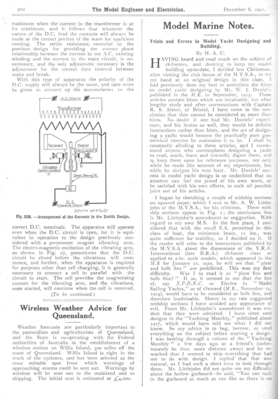
n ° wn December 8, 1921. The Model Engineer and Electrician. Model Marine Notes. maximum when the current in the transformer is at its maximum, and it follows that whatever the nature of the D.C. load the contacts will always be made at the correct portion of the wave for sparkless running. ‘The series resistance, essential in the previous design for providing the correct phase relationship between the current ia tne A.C. existing winding and the current in the main circuit, is unnecessary, and the only adjustment necessary is the adjustment for the correct time interval between make and break. With this type of apparatus the polarity of the D.C. supply will always be the same, and care must be given to connect up the accumulators to the AC Mains g— Transformer Trials and Errors in Model Yacht Designing and Building. By Hs A. Cs AVING heard and read much on the subject of 18-footers, and desiring to keep my model building up-to-date, I decided last Christmas, after visiting the club house of the M.Y.S.A., to try my hand at an original design in this class. ! shall be had previously done my best to assimilate the hints on model yacht designing by Mr. W. J. Daniel’s published in the M.E. in September, 1915. These articles contain hints which are invaluable, but after lengthy study and after conversations with Captain R. S. Alston, of Bristol, I have come to the conclusion that they cannot be considered as more than hints. No doubt if one had Mr. Daniels’ experience, and his brains as well, they would be definite instructions rather than hints, and the art of designing a yacht would become the practically pure geometrical exercise he maintains it to be. I constantly alluding to these articles, and I recommend anyone who contemplates designing a yacht to read, mark, learn and inwardly digest them, and to keep them open for reference purposes, not only while he reads this account of my experiments, but Conracts aE Justable while he designs his next boat. Mr. Daniels’ success in model yacht design is so undoubted that no “D amateur can feel too proud of his own work, or be satisfied with his own efforts, to suck all possible juice out of his articles. D.C j Charging Mains — ZENITH M’F’G.C? Fig. 33B. —Arrangement of the Currents in the Zenith Design. correct D.C. terminals. The apparatus will operate even when the D.C. circuit is open, for it is equivalent in operation to the design previously considered with a permanent magnet vibrating arm. The electro-magnetic excitation of the vibrating arm, as shown in Fig. 27, necessitates that the D.C. circuit be closed before ‘the vibrations will com- mence, and further, when the apparatus is required for purposes other than cell charging, it is generally necessary to connect a cell in parallel with the circuit to start. The cell provides the magnetising current for the vibrating arm, and the vibrations, once started, will continue when the cell is removed. (To be continued.) Wireless Weather Advice for Queensland. Weather forecasts are particularly important to the pastoralists and agriculturists of Queensland, and the State is co-operating with the Federal authorities of Australia in the establishment of a wireless station on Willis Island, 300 miles off the coast of Queensland. Willis Island is right in the track of ‘the cyclones, and has been selected as the most suitable spot from which warnings of approaching storms could be sent out. Warnings by wireless will be sent out to the mainland and to shipping. The initial cost is estimated at £4,000. I began by sketching a couple of midship sections on squared paper, which I sent to Mr. A. W. Littlejohn of the M.Y.S.A., for his criticism. These midship sections appear in Fig. 1; the continuous line is Mr. Littlejohn’s amendment or suggestion. With regard to my own M.S. In the first place, I considered that with the small S.A. permitted in this class of boat, the minimum beam, 11 ins., was quite sufficient for stability; so I decided on it. If the reader will refer to the instructions published by the M.Y.S.A. about the dimensions of the Y.R.A. International (late B.R.A.) 18-footer class as applied to 2-in. scale models, which appeared in the M.E for January 22, 1920, he will see that ‘‘ plate and bulb fins” are prohibited. This was my first difficulty. Was I to read it as ‘‘ plate fins and bulb fins? ’’ If so, it seemed to me that the fins of, say X.P.D.N.C. or Electra in ‘‘ Model Sailing Yachts,’’ or of Onward (M.E., November 12, 1914), would have to be considered as bulb fins, and therefore inadvisable. Hence in my two suggested midship sections I have avoided any appearance of evil. From Mr. Littlejohn’s amendment it was evident that they were admitted. I have since seen designs in the ‘Yachting Monthly,’ published about 1917, which would have told me what I did not know. So my advice is to beg, borrow, or steal everything on the subject before starting a design I was looking through a volume of the ‘‘ Yachting Monthly’? a few days ago at a friend’s (unfortunately he lives some distance away) and he remarked that I seemed to skip everything that had not to do with design. I replied that that was natural, as I had such a short time to-look through them. Mr. Littlejohn did not quite see my difficulty about the hollow garboard—he said, ‘‘You can tucks in the garboard as much as you like as there is no
December 8, 1921. The Model Engineer and Electrician. d measurement in this rule. You can get a muc h shallower body than this (referring to his own section) if you want to, but it pays, in My Opin ion, to go for you a get the heavy sail formula. that there displacement for weight.’? I was no d my two Littlejohn. — This water to be sailed and the Round largest. Pond, man’s I sail sailing is to 75 third or sary, and sary per on. area fourth suit, the either, L/S 1920]. as d under- M.Y.S.A. place will Pay sail, chiefly on but on, say, the a races large are sailed a is not so neces- is not sO neces- I went for a h Ibs the too really design was light. I Was wrong, three and maximum will often trap I fell into, I must now mention which also displacement of my boat. 1910, Kitchingman accounted for , the Area of M.S. x the area of the which, weeks am at not of course, is midship sec- x 27.65 I do not know what ae men think, but personally | object to being give n rules, and not to be told how they are obtained . So | will explain this one. The area of the M.S. a planimeter (see obtained M.E., vol. in my case xx, by Page 290). The length of the L.W. L, must be decided by the designer. The volume of a rect angular box is foun d by area of end by length. In the same way if the boat were of the same section as the M.S. all the way along the of M.S. experiment an L.W.L., by L.W.L, by ordinary boat volume of a its volume But previous it has designers eccupies solid with been that about length would be: the =—~ by body of of the 100 = L.W volume we shall obta in approximately the volume of the boat, in cubi c inches if we have used inches in the other meas + in urements. a pound 27.65 gives the of There are 27.65 cubi c fresh rough water, so weight in the Ibs. called the prismati c co-efficient. is volume The +55 is The approximatio n because some boat s are much fine r than instance, in, the case of a canal barg e .55 might be -8, rough, others; for the very “45. look ihat, Fig. about board flat-floored It will .55 using 1, be for I 16.6 or in boat seen my the got Ibs. it the case of a finekeel might now T and as little my as -4 or error arose. | co-efficient, and found dot-dash-dot When be how prismatic 16.9 Ibs., what I Rut as a matter of fact really ought I have had since completing the design now that she is as she is, and Poole sorry Bilge cure lined using found that trial M.S. the dotted | | Figs. 1 and 2.—Trial Midsh ip Sections, – my reasons stand in now to for the find have used. lowing :— wanting in line a hollow garwas allowed 1 drew out another M.S., Fig. 2, a lighter displacement light of subsequent experience. what prismatic co-efficient boat Well, I should I find on referring to my notes the fol- 22.6 (area of trial M.S.) area found .L. and sectional area =area of M.S. ; therefore if we take .55 of this inches it was out the time to Frege when I found I light It is as follows :— length on L.W.L. was above some and the length of L.W.L. or lis: fo- the In the M.E. for 1909 and published given lift, another very -excellent beginners’ articles on yacht designin g. For a beginner they cann ot be improved upon , I He gives a rough rule for arriving at the displ acement of a boat tion, completed said require more than the 1,280 sq. ins. or so that she is allowed ; that is, if she is sailed chiefly at Poole or Southsea or Gosp ort. the decided my displaceme nt, as to have done. shallower body with nearer the minimum than the displacement. TI du hot expect my boat with of the question for me to spare through the whole busin ess again under S.A. Consequently When 1.6 the displacement Ibs. but it will be evide nt from this that I thought it would be as well to deceive myself into thinking I wanted light displ acement, for it was this error whic the if 15.96 that I had other reasons for want ing a light displaceme nt boat the question of heavy displacement A_ as areas all sections measured by planimeter, and the displacement calculated by Simpson’s rule, I foun d that it worked out as 16.4 Ibs. (without the lift), whereas I expected it to be nearly 18 Ibs. So | was 34/D is out 17.8 Ibs. without the lift applied. [The to has been fully expla ined in the M.E. of 36 which are near the sea, and of heavy ys worked about alluded from : possible the take cent. where knew introduces. Poole or Solent wate rs, where rule I D in the 18-footer form ula It will be noticed that in for a shallower body than went where L~ measurement, displacement. sections a 4 Mr. the in course, repeat it here Stood in the metr e rule. represents type Of and calculated the approximate displace ment again, using .55 as Prism atic co-efficient. The displacement x 35-5 (L.W.L.) x 155 27.66. =15.96 Ibs. This was with lift applied. I assum ed that without the lift appli ed the boat would be heavy enough. Now the M.S. on without lift=24.2 sq. therefore completed ins. and the L.W.L. =37 ins., Sa = 17.8 Ibs. about. 27.65 24.2 But rule the design as on X xX .§5 calculating on the basis of Simpson’s from the whole design it works out to 16.4 Ibs. So there is 1.4 Ibs. difference, and if my work has been correct the boat should weig h 16.4 Ibs. and with the lift applied, about14.2 lbs., which is not much above 13.88 Ibs., the minimum allow ed. I do not see how to calculate the correct prism atic co-efficient Let in any way but the following :— x—the prismatic co-eff icient. 24.2 X 37 27.65 X*% = 164.0% = 27.65 X 16.4 as 24.2 X 37 Whence x =.506 about , so that I should have taken .5 or .51- as my prismatic co-efficient. If my
The Model Engineer and Electrician. 504 argument is not correct I shall take it as a favour if any reader will put me right. I have spent some time over this, as obviously it is of great importance, especially where displacement matters as much as it does in the 18-footer formula, that one should be able to form an approximately accurate notion of what the displacement is likely to be without going to the trouble of designing the whole boat and finding one has to start all over again. On this subject Dixon Kemp (11th ed., p. 423) has very little to say, merely that for most sailing yachts this co-efficient varies from .5 to .55. On again referring to Fig. 1, my two trial sections show very much less draught that Mr. Little- john’s. raking My reason for this was that I wanted a keel. Referring to Mr. Littlejohn’s own 1920 design for Impudence on the 8th April, number of the M.E., the bottom of the keel is horizontal, and so it is, I think, in the latest of Mr. fied sea and Feltwell’s designs as I have seen them exempliin the two boats Mr. Braine brought to Southlast summer (August.) Every man to his taste, for reasons gathered from Dixon Kemp, and from early articles in the M.E. by Wilson Theobald, I desired a raking keel. Also always there is the consideration that with their small S.A. it is not of such importance in 18-footers to keep the centre of gravity of the lead as low as is a sine qua non in a 1o-rater or a metre boat, especially the latter, i x X. Fig. 3.—Laths used for Seribing Ares of Circles. under the rule, which allows a large sail-spread. So my keel rakes, though not so much as would appear from Fig. 1. I have wondered why many of these boats have flat keels instead of the more pleasing (to the eye at any rate) rounded section which appears in Fig. 2. I see no reason for it, except again to get the weight as low as possible. Certainly, where ponds have gravelly paths beside them the square corners would soon get worn, though of course a sensible man would fit a sole of brass. With regard to the length of the L.W.L., which is another thing the designer has to determine for himself. Personally, I have a leaning to easily driven boats with flattish floors, which means that the angle between the water surface and the profile will be small, therefore the sections at the fore and after ends of the L.W.L. will be full, or that the O bow and O stern measurements, which help to make up L on the formula will be relatively large. Therefore the L.W.L. must not be too long. With full sections one trusts to the boat’s lengthening her water line well when heeled, which of course is the object of overhang. So I chose 35.5 ins. as L.W.L. lift applied. It is advisable here to take Mr. Daniels’ September, 1915, article and to number the paragraphs, as I shall be constantly alluding to them. In the fifth paragraph of his article Mr. Daniels, says: ‘‘ The length of the L.W.L. will determine the angle that the profile makes at each end of the L.W.L. with the latter.’’ This seems a bit cryptic at first, but it is clear when one thinks of the M.S. in connection with the L.W.L. When the M.S. is decided on the floor should be continued on to the centre line as shown in Fig. 2. The point P ‘will be the lowest point of the body; and a curve drawn through this and through the ends of the December 8, 1921.° L.W.L. will form the basis of the sheer plan, and will give the angle of the profile fore and aft. But Mr. Daniels has not said here where the midship section should be placed—longitudinally that is. In the article on Prospero in ‘‘ Model Sailing Yachts,” he says: ‘‘ By placing the largest immersed section slightly behind the middle of the L.W-L. it is arranged to come exactly amidships when heeled I believe ‘t is to the maximum sailing angle.’’ usually situated about .55 of the L.W.L. from. its fore end. [N.B.—This is the point where the G is measured in metre boats.] But if one employs a raking midship section, I do not remember to have seen anywhere any hints to aid the beginner. I should think that if one made the greatest beam on L.W.L. to be situated about .55 x L.W.L. from fore end, and the greatest beam on deck aft of that, and the greatest beam on the lower water lines correspondingly forward of it, that one wouldn’t be far wrong—the amount of rake, of course, to be according to taste. I had now the M.S. on the body plan, and a trial profile on the sheer plan: I did not lead the profile line right up to the stern head at first, as the buttocks and bilge curve were not yet attempted. _ For the half-breadth plan I had the ends of the L.W.L. and its greatest beam; and the position of the greatest beam on deck (through the raking M.S., which I had drawn on the sheer plan and which can now be inserted in the half-breadth plan as appears on p. 244 of the M.E. for September 16, 1915. 1 am assuming that the horizontal lines denoting waterlines on the sheer and body plans, and buttocks on the half-breadth, have been drawn. By the way, for these it is not advisable to use a T-square, but to draw two lines at right and left-hand ends of the paper perpendicular to a base line, and to measure off equal distances—-usually 1 in. (full size) up the side lines and join the points. The T-square is not accurate enough for long distances. For economy’s sake I draw the sheer and half-breadth plans half-size; also some people say that it is impossible to obtain a complete view of the whole at once if too large. Linton Hope, I believe, was most emphatic on the point; the body plan I draw full size to save the trouble of enlarging it when making moulds (if for a planked boat), or templates (if for a dug-out). Also I think I can judge of fairness better if the drawing is not too small, and again errors in the other two plans are more apparent when multiplied by 2 and transferred to the body plan. To continue from Mr, Daniels: ‘‘ The deck line should now be drawn. This should correspond in breadths and curvature either side of the point of greatest beam.’’ (6th paragraph.) This is not easy at all. Consider that there is to be a transom at the stern, while at the fore end the deck line meets the centre line (on the half-breadth plan). How far fore and aft of the point of greatest. beam is the equal curvature to extend? It seems that although we are instructed to draw the deck line next, we cannot do so until we have decided on the breadth of the craft right aft. So we had better leave the deck line for the present, and have a shot at the transom, for which we must go to the body plan. Refer here to the skeleton body plan on page 245 (M.E. No. 751). So far we have nothing drawn, but the M.S. which is repeated_on both sides. Paragraph 7 begins ‘‘ across the mid-section This is simple enough. draw a diagonal E.E.’’ i
December 8, 1921. The Model Engineer and Electrician. But if one refers to other sets of lines by W.J.D. (thus, for short, in future), one finds that in many of them this diagonal is a pronounced curve. I have tried to discover why this is so, and 1 give my 1 daresay W.J.D. results for what they are worth. will have many a good laugh in his sleeve before I have finished, but he must look on his articles as a puzzle set us to solve and not jeer too much if one’s efforts are puny. Take the design of Prospero, – curve I imagine that if the bilge for example. were a straight line in the body plan, it would make all the sections fuller lower down, especially those right aft, or higher up if the line were drawn normal to the bilge of the M.S., especially right forward. This would bring the overhangs out of harmony with the under-water body, as W.J.D. ex- presses it, which I take to mean chiefly that the C.B. _would be shifted too far aft or forward when she ‘heeled. Hence if harmony is to be preserved, and a reasonable freeboard acquired, the line must curve. At any rate, I found it wanted to in my design, and I tried several before I got it right. Also it may be found that unless it 1s curved, it is impossible to get the four views of the bilge curve to be properly fair, namely, the end view appearing in the body plan, the side elevation in the sheer plan, the plan in the half-breadth plan, and the view in its own plane. Then there is a difficulty I cannot fathom at all. If the line is curved in the body or 505 not, or whether any of it is, which is what I take it W.J.D. means by ‘‘ of uniform curvature.” Euclid, of notorious memory, has stated (and proved) that angles in the same segment of a circle are equal. Take two pins X and Y (Fig. 3). Screw two thin laths together so that the angle between them is, say, 170 deg. (using a protractor); put the laths on the paper so that the pins are up against the inside. edges of the laths, then the inside point of intersection of the laths will describe an arc of a circle if the laths are moved about, always keeping them up against the pins. (See Fig. 3.) It now we put our pins at the ends of our trial deck line, or, as W.J.D. says, the curvature should correspond on either side of the greatest beam, say we put our pins half way between the point of greatest beam and the ends, on the deck line. Let Z (Fig. 3) be a point*on the deck line between the pins, then if the laths are set to the angle XZY and moved about, and if the point Z (the intersection of the laths) follow the curve, then the deck line is an arc of a circle. It is well to make a decent job of these laths; for a half-size drawing each might be: 20 ins. long, about 1 in. wide and 3 in. thick; a small brass bolt with a thin flat head might act as plan, it does not lie in one plane at all, really, and there is a small amount of foreshortening if it is drawn in its apparent plane as a diagonal. Again, when drawing it in its own (so called) plane, does one measure the breadths on the body plan round the curve or straight? Personally I measure them straight along the chord of the arc, and I got the four views fair all right. But whether I am right or not, I do not know. I conclude that if the boat has a fairly flat floor, the bilge curve in body plan will curve down as it comes towards the centre line in the body plan. Return then to paragraph 7. The diagonal E.E. in my fairly flat floored boat was likely to be curved a bit, and the only thing to do The next 13 lines of was to draw a trial E.E. paragraph 7 are simple enough, but he then goes on ‘‘taking the width of deck at the extreme end of the counter, and also the distance above the water line as indicated by the height to which your profile has risen, at this point draw a tentative transon section.’? Now, I said just now that we must leave the deck line till we had the transom, and here W.J.D. assumes that he has the deck line (at the counter end), and uses it to draw a transom. I think it is just a matter of trial and error. I drew a tentative transom before I drew the deck line, then transferred its breadth to the half-breadth plan, and, taking trial overhangs, drew a tentative deck line. The after overhangs can be got more or less easily ; we can see by examining other designs or boats what the freeboard right aft is, and knowing this, and having the profile to above the L.W.L. aft we can continue this profile in a stranght line (as a trial only, I altered mine after I had the after buttocks drawn) till we reach our required freeboard. The forward overhang is more a matter of guesswork. But W.J.D.’s notion of similar curvature will assist us here. We have two points for the deck line now at the transom and at the greatest breadth. Fig. 4.—Illustrating Points in Design. a hinge. From the article in M.E., No. 752, I gather that W.J.D. likes the diagonals also to be arcs of circles, and we shall want the laths again. 1 had not this device when getting out my design. I had no time to judge more than roughly of the similar curvature. It could also be done after this fashion. Assume a curve ABC. If AC be joined, and divided into, say, ten equal parts, the heights of the curve about AC would be equal at equal distances from the centre of AC, if the curve is an arc of a circle. The section lines on the half-breadth plan cannot be used for testing the curvature of the deck line because they are not perpendicular to the base line corresponding to AC above. They could be used in the case of -a diagonal which ends both fore and aft on the centre line. Well, we can now form some idea as to whether our deck line fulfils W.J.D.’s requirements as to similar curvature. I found one of the easiest mistakes to make was to forget that the lines one had I think it is best to take a parallel batten and draw the deck line where it looks right. Now we want drawn were only trials—the designer must always keep in mind that the deck line especially is only a trial—it may have to be altered when the whole a method for finding whether it is an arc of a circle design, has been got out, as will appear later. Since
O N in Fig. 5 being measured at a distance M N from section 4 equal to L K in the sheer plan. This we now have a deck line, we are in a position to complete W.J.D.’s instructions in par. 7, and, after deciding on the freeboard at the stem head, a deck sheer line can be drawn (G G G., Fig. 2, W.J.D.). paragraph he mentions drawing the it is required to prove its fairness on the half-breadth bilge plan. curve in plan, but he does not give instructions for drawing it until par. 19,.so we leave that for the present. Now with regard to the bilge curve If anyone wants an exercise in design now, let him take the given midship section (Fig. 2) and the position of the lines given in Fig. 5, and com- in its own plane (par. 13.) In the third line of par. 15 W.J.D. says: ‘‘ From the midship line to the bilge.’’ Here he means on the body plan; in the fifth line, ‘‘ the deck plan’’ means the half-breadth plan. In the sentence beginning: ‘‘ You now draw the original . ””, he was referring again to the plete the design. W.J.D. says somewhere that the designer must be particular to get his points exactly right and not nearly so. I should like to say that if in my Fig. 5 the distances do not appear exactly right it is the fault of my reproduction of my original draw- body plan in the ‘figure at the foot of page 245. He would have simplified matters by using more letters instead of words. I will repeat his ‘figure, insert- ing other letters (viz., Fig. 4). E.E. is the bilge curve (or diagonal) mentioned in par 7, line 1. X’B is the stern half of the same; x’B is equal in length to x’/A, and it is drawn so as to be normal to the bilge at x’ and to the trial transon curve at y. (‘‘ Normal’ is the name given to a line perpendicular to a curve.) ‘‘ The point found in this manr’? (W.J.D. in last two lines on p. 245) is B in my figure 5. By is then measured and transferred to the lower side of half-breadth plan on the vertical line representing the transom section. I am not recommending my own design, but merely suggesting a useful exercise 6 oy ae) EY | ae Bitge curve. 3 AL 2 Z Cc La / cae a – Latermal LW oe this of course, assumes that trial views of bilge curve have been drawn on body and sheer plans, and that oe In December 8, 1921. The Model Engineer and Electrician. ; 506 In other words, we have now discovered a point at the right- hand end of the ‘‘ View of bilge curve in its own plane,”’ in W.J.D.’s Fig. 2, p. 245, and can draw a trial line for this as W.J.D. says, in par. 16. the stern “above the L.W.L., which I said before should not be drawn in at the same time as the under-body profile. Now by measuring vertically downwards and upwards from the L.W.L. in body plan we can find 3 points which will enable us to draw a trial side elevation of the bilge curve on the sheer plan, appearing in the left-hand figure of W.J.D.’s Fig. 2. Also by measuring horizontally outwards to right or left on the body plan, we can get 3 points through which to draw a plan view of the bilge curve, appearing in the right-hand figure of W.J.D.’s Fig. 2. We now have four trial views of the bilge curve. W.J.D. says now in par. 19: “When once this line is true in all three plans, the rest is simply a matter of routine.’’ But he has just instructed us to draw four views—so it will be safer to read ‘‘ four ’’ for ‘* three,’’ as the more checks we have on our work the better. I found some difficulty at first in grasping W.J.D.’s manner of fixing these lines. He says: ‘‘This (i.e., the plan view of bilge curve) is easily checked for its correctness by seeing that where the diagonal crosses any water line in the body plan it has the same breadth on the deck plan in the same fore and aft position as the spot where the diagonal cuts the water line in the stern elevation.’’ All quite correct, but a deuce of a sentence to get hold of all at once. The stern elevation of course is the sheer plan. I have reproduced a portion of the lines of my boat to explain what is meant (Fig. 5). The bilge curve appears dotted in the half-breadth plan for the-sake of clearness. Consider Fig. 2 in connection with Fig. 5. Then the bilge curve W.L.A. in Fig. 2, at O and the distance ON in Fig. 2 must equal the distance O N in Fig. 5; Dai S/R The crux of this is its forward end; this forward end will give us the fore and aft position of the end of the bilge curve, and as we have its height on the body plan it can’ be transferred to the sheer plan, and so gives us a point through which to draw SSS fine yy ee 3 all i Bilge curve Fig. 5.—Some of the Lines of the Writer’s Boat. ing, for the original is exactly right. 1 have not the facility for correctly using the drawing pes that I could desire. I think W.J.D.’s instructions are fairly clear to anyone who understands how the lines of a boat correspond, once he has arrived af par. 20. Par 18 is continued in par. 21, where the words, ‘‘ Sweep in a cross-section,’’ etc., refer to the section at the bow end of the L.W.L. and which appears on the body plan. In par. 22 the first semtence would be clearer if ‘‘ on the half-breadth plan ~ were inserted after “‘first water line.’? Note particularly the first sentence of par. 23. In par. 25 the last word in the first sentence should be ‘‘ cross sections ’? (plural). Par. 27 is very important, and might have bees inserted earlier in the article. This sort of thing shows that no one should attempt to construct ® design, or a boat, or an engine, without first read ing very carefully the whole of the article in ques tion. In this case the editor published all three
December 8, The Model Engineer and Electrician. 1921. 507 parts of the article in three consecutive numbers, and thus simplified matters; it is to be regretted that such a course is not always possible. It is to the meaning of this paragraph, or rather of ‘‘ helow the turn of the section into the keel.’? To very looks at the half-breadth plan; when it difficult, as I find, to put everything exactly in its right order of sequence. Let the reader now number the paragraphs in the second part of W.J.D.’s article in M.E., No. 752. There are 47. The uniform curvature of the bilge curve fore and aft of the M.S. (but how far fore and aft? that is the question!) alluded to in Part I, par. 27, occurs again several times in Part II, or the idea contained in it does; in par. 3 W.J.D. says that were it not for the use of a transom the perfect hull form would be exactly the same shape aft as the forebody reversed, which of course means that the lines— practically all of them—would be arcs of circles, such as appear in W.J.D.’s Fig. 7. . Again, from his definition of a stream line in par. 6, it is evident that, since the bilge curve crosses or should cross each section at right angles to the tangent at that point, he considers the bilge curve to be a stream line. One must here disabuse one’s mind of the idea of stream lines as applied to the forms of fishes and of aeroplane wings, as the boat moves on the surface of the fluid, while the fish or the aeroplane moves in it. Again, it is directly alluded o in pars. 43, 45, 46, and 47. From W.J.D.’s insistence on this point—the uniform curvature of diagonals, and deck line (which of course is really another diagonal)—I feel confident that this is the final basis on which he builds his designs, and that this—added of course to his ability as a sailer of | models—accounts for his multitudinous successes. have not yet had time to experiment fully in this direction. The 18-footer lines I have produced appear on rough examination to approximate to arcs of circles in these lines—but far more than mere rough approximation would be necessary, I think, and I hope to have other shots later on. Whatever Mr. Daniels’ method is, he would be \a fool to publish it broadcast, especially now in view of his coming (it is to be hoped) contest with the American model yachtsmen. Wasn’t it lovely to read that they couldn’t sail this year because they They had no. experience in building 75-footers! find contrary flexure in is obvious in all keel boats that there is a very pronounced con- trary flexure or inward hollow in usually the first water line below the L.W.L. But where is the absence of contrary flexure to begin? Mr. Daniels says ‘‘ below the turn of the section into the keel.’’ Captain Alston got it out of him. He meant where the reverse curve of the midship section, turns into the keel. So one should look at the body plan; see where the reverse turn at the hollow garboard begins, and no water line below that should shew a contrary flexure in the half-breadth plan to steer it into the stern post. This also is a very important point in designing, for the reasons that Mr. Daniels gives in pars. 30 and 31, of Part I. Model designers owe a debt to Captain Alston for this, in addition to that already owed him for the graph showing the inter-relation of the factors in the 18th-footer formula. (M.E., January 22, 1920). (To be concluded.) Radio Engineering. By Capt. H. pe A. DonisTHORPE, A Loud Speaking Device. Considerable interest has been aroused recently by reference in the Press to a new invention due to two Danish engineers, Messrs Johnsen and Rahbek, whereby radio sigals can be considerably magnified without the aid of thermionic triodes. The invention relies on electro-static adhesion effects of certain substances. Another interesting arrangement which can be To External Circuit O Terminal ie HBbonite Bush make no bones about saying they are going to have experience, although Mr. Daniels will naturally A find it hard to get any similar boats built on this side as trial horses. It reminds one of Sir Thomas Lipton’s efforts at getting a reasonable rule to build a water line one of course to. To refer again to the uniform curvature—of course a huge trammel could be,made for describing the arcs and might perhaps be more convenient to use if sufficiently lightly constructed; and one could alter one’s radius, and use known radii more quickly, and have more idea what one was doing, and be better able to compare results. To return to Part I, par. 27. It will be noticed that he says ‘fin conjunction with a good deck line ’?; this will remind the reader that his first deck line is only a trial one, and that others will probably have to be drawn later on. The most requisite quality on the part of a beginner at yacht designing is patience. And in building, too, for that matter. never be satisfied with ‘‘ that’s near must He enough.”’ Part I, par. 30, contains more very useful matter. But as it stands in the text I think it incomprehen- sible. My friend Captain Alston, of Bristol, met Mr. Daniels some time ago and questioned him as Fig. 1.—The Loud Speaking Device, with Cover Removed to show Crystal. employed for the purpose of magnifyng feeble wireless signals utilises the property possessed by certain crystals to generate electrical charges when subjected to mechanical stress. Such crystals are those whose construction does not rely on the symmetrical arrangement of their atoms and molecules. Quartz, tourmaline, boracite, and rochelle salt possess this property and the last named gives the best results known.
518 2 The Model Engineer and Electrician. Model Marine Notes. Trials and Errors in Model Yacht Designing and Buiiding. By H… A.C: (Concluded from page 5°7-) With regard to the calculations for displacement for -and centre of buoyancy, W.J.D. is clear enough of a planianyone. | would only add that the use hours of meter is practically a necessity, and saves ng that one’s what -may: be useless labour supposiagree with the trial sections are not fair, or do not of the theoretical curve of areas. The formation curve forward and curve of areas by a versed sine simple. a trochoid or a versed sine curve aft is quite W.J.D. prefers versed sine curves both ends— ls obviously, again, he is thinking of his diagona curve -of uniform curvature. But the point about this of the is this; Where is the perpendicular diameter ’s figure generating circle to be drawn? In W.J.D. ins. 21 son page 269, from the scale, it is about 272 the from C.B. the fore end of L.W.L. and on page fact most is 21.4 from this point. As a matter inof the same people put the centre of this circle C.B., which vertical line on the drawings as the on other the seems a sensible thing to do, though, to show where thand, since the curve of areas is body begins, it the fore-body ends and the afteris quite possible with a raking midship section that Anythe C.B. would not be the right place for it. ins., and way 21 ins. is not the same as if 21.4 it is possible I should very much like to knowto take this centre with any accuracy to know where to draw supposing—as is often the case—one wants design is finished the theoretical curve before the Dixon Kemp and the actual curve has been drawn. should not says that the theoretical curve oftheareas sections forced be drawn first, and the areas of the position of this to suit it; this may mean that d on first; generating circle should not be decide areas has been but that when the actual curve doffrom the highest drawn, the perpendicular droppe as the diameter point on this curve should be taken suppose if the M.S. of the generating circle. I were not a raking one, appearing on the sheer plan the centre of this circle would be vertically under with the it. There is another point in connection In my design ‘actual curve of areas when found. ical curve I got my curve of areas as near the theoretody of the as I wanted it, using only thetheunderb s on. the boat formed by continuing all as ifsection the boat had body-plan into the centre line, accordance with a canoe body; which is inI had drawn out the when -accepted practice. Then lead, I found it impossible sections of the keel and fair curve of to draw what looked a_ sufficiently ning the keel. areas, including the sections contai haste to This bothered me, and I wrote off topost know’ what Mr. Littlejohn and Captain Alston the former’s reply: ‘‘ I they thought. I will quotevery thing myself have come against the Dixon same Kemp lays it down several times. Of course, ating for this that one must include the fin in calcul of his way to ex- curve of areas, and he goes out of the forefoot away plain how by cutting a piece1.e., brought nearer to the curve can be corrected, the versed sine curve, or by adding a piece, as the area of that particase may be, to increaseall the very well when one is cular section. This is _ dealing with straight stemmers as he was, but when one gets a December 15, 1921. to-rater fin for instance (like say XPDNC’s): you cannot get a displacement curve at all by including the fin keel, as you will see. To get over this I omitted the fin, and carried the sections in that region into a canoe body, for the purpose of the curve of areas. I have not found any difficulty with 18-footers where the fin is not scooped out, or where the fin is similar to Impudence. 1 have three different 18-footer displace- ment curves enlarged on a sheet of paper, and each fresh design I produce I add the new curve to the others; it is interesting for comparison.’’ Thus Mr.y Littlejohn. Captain Alston’s opinion is practicall Nevertheless, I will append (Fig. 6) my the same. own curve of areas of the underbody, excluding keel, and will show my attempt at drawing a curve of areas, including keel. It will be seen that the inside continuous curve (from the sectional areas of the hull body only) approximates closely to the versed sine curve forward and the trochoid aft, while the outside curve (from the sectional areas of the hull and keel) is very much inside its corresponding theoretical curve. Mr. Littlejohn said that he found no difficulty with 18-footers. I presume he meant in getting some sort of displacement curve— for I do not see how, say Impudence, could avoid having a more or less similar curve to that shown. It takes-some time to work out the curves, or I should have done it from the Impudence design—but I have not had time. The reader will also notice that I have—differently from W.J.D.— used a trochoid curve aft. This is based on other designs with this curve—I daresay I shall follow W.J.D. more fully another time. Also I have not put the generating circle vertically under the C.B. My reason for this is, that when I did so my displacement curve was all outside the theoretical curve aft and inside it forward—while if I moved the generating circle forward to the position shown my curve approximated much more closely to the theore- tical one. This leads me to argue that really it is almost impossible to say beforehand exactly where this circle must be placed, and that on experience of a similar kind Dixon Kemp must have founded his dictum that it is a mistake to draw the theoretical curve first and force the design of the sections to agree with it. As a matter of fact, I did do that once, with a boat that had not a raking ‘midship section, and as far as I can see she is a decidedly speedy boat—especially running. 1 refer to Dryad, whom some of those who will read this have seen. If both ends of the curve areas correspond to versine curves, the volume will be half the area of the M.S. x the L.W.L., or, in other words, if r=the radius of the generating circle, a=the forward portion of the base line and b=the after portion. The volume of the immersed portion will be r(a+b) cu. ins. thus the distance of C.B. ahead of generating circle will be .298 (a—b) ins., i.e., assuming the curve to be drawn full size. In this case, of course, the prismatic co-efficient is .5 exactly. The gist of Part III of Mr. Daniels’ article for the first 25 paragraphs appears to be this. The designer must imagine his craft heeled to various angles, and find where the C.B. of the immersed portion is. If it is forward or abaft of the C.B. when upright, the design must be altered until the of difference is negligible. Now the whole point this lies in par. 18, at the foot of page 289. ‘‘ It has,) Daniells’ therefore, been the writer’s (i.e., Mr. practice to imagine the whole of the displacement to
The Model Engineer and Electrician. December 15, 1921. te thrown into one side of the boat, and to ignore the apparently immersible portion which on _ the drawing will show as submerged.’’? The difficulty _ is as to what he means by the ‘‘ apparently immersible portion.’’ The only thing I can see to be done is to suppose he means to use that portion of the boat included in the in-wedge and the rest of that half of the boat ‘on the same a Fore end. a : side as the in-wedge. This reasonable thing During my stay at Poole this year I have walked along the platform and watched a boat sailseems a to do. Say = x ing / iff / 200 yards in ward side towards me% and it was quite clear that when sailing properly the hull was exposed right to : the garboard all the time except i. at the ends, and there the pressure seemed H to be almost entirely on the lee side.. This finding N ry various angles of heel is a laborious job—but, as | said before, patience is the first requisite designer—that, for and a a this is It planimeter. C.B. business that may for it imperative make the deck line to be radiits from altered cally original form. It seems a difficult and boring thing to do when one has got : | . 2 \ of the C.B. of the craft at Fig. 6.—Curve of Areas. I ” over from me with her wind- / / for a straight line not more than five yards or so away all one’s points fair, to have to wash out the top as the case sides fore or aft, mav be, but it is necessary. \ It mav 13 14


