- Black Watch – A 50-800 Model Yacht. By J. B. Duncan.
- The construction of fittings, spars, sails, and the final hull treatment for a 50-800 Class model yacht, emphasizing custom work, material selection, and finishing techniques. He provided specific instructions for making metal fittings from materials like brass tubing and empty shell cases, shaping spruce spars, and finishing the deck with drawn plank lines, while also recommending purchasing professionally made sails and adding required safety features like a bow bumper.

a ‘ ie ack Watch A 50-800 MODEL YACHT By John B. Duncan Staten Island Model Yacht Club construction of hull was N LAST month’s article thebe basic getting on with the masts, spars, now fime to s been a debatable point among I described. It issubje ct has alway and fittings. This others go to the prefer simplified gear; own model yachtsmen. Someicate imagination. their of ts gadge d extreme and have compl be bought, can gs fittin dable depen Good don’t. me —-so Some work not s0 It’s own? your make but they cost money. Why not these how ng showi s detail found be will ngs hard. On the drawi d as Avoi able. obtain easily fittings are developed, using material spars into the mast and much as possible the screwing of fittingsand cause a break during as this has a tendency to weaken them of the fittings will ing finish the in care little a heavy blow. A no idea You spent. repay you for the little extra time made enhancehave beauty the neatly s fitting how mast, spars, and marks er hamm or file, , of the vessel. See that all surplus solder ed. polish and h smoot are es surfac the are eliminated, and that that see d, finishe ium chrom s fitting your have to prefer you If good polish with fine steel no soft solder is used. However, a keep clear for a considerable will that surface a p develo will wool protecting the wood hed, repolis be time, and at intervals can work by shielding with a piece of tough paper. Making Metal Fittings available The different sizes of brass tubes required are usually stores. supply model the from ble obtaina or towns large in most store, a such having in te In New York area we are very fortuna one l materia of kind any almost select and where one can go wants and secure it in small quantities at a reasonable price. It will be noted that empty shell cases have been used for end fittings; these make a wonderful job and look good with their tapered ends. Any National Guardsman or member of a rifle club will be pleased to save them for you. After cutting, file the openings and lugs in the various parts smooth, and before folding over the lugs to the required position, it is advisable to soften the brass by heating the part to be folded to a cherry red over the gas stove and quenching quickly into a glass of cold water (quench before folding). Don’t be afraid to ask some of your more experienced friends how to solder, or use the sweating or tinning procedure, but should your immediate friends not possess this knowledge, and you try it yourself, always remember the parts to be joined together must be clean and free from all grease. Your soldering iron must be well tinned and of proper temperature, otherwise the solder won’t “run” properly. The details shown in the plans are self-explanatory, no great difficulty should be experienced. It is true, simpler fittings can be used, but the ones described are copied from the original; and being both strong and comparatively light, they have stood the test and if, as I said before, they are made with care, will look good and shipshape. Mast and Spars . Procure from the lumber mill a good piece of straight-grain spruce, free from knots and shakes. Have it cut into strips to sizes given on plan, allowing a little on length. After all four sides are planed, lift the dimensions from the drawing and mark out your guidance lines. Cut to shape as indicated, checking in THe Mopet CRAFTSMAN
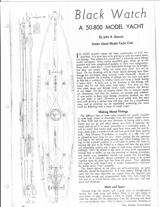
for your end fittings, which you have already completed. See that fittings are snug and are in proper alignment. Rub down your mast and _ spars GMeatQeen smoothly; then give them one coat of varnish before putting on the fittings. Insert the brass screws at the proper intervals for soldering on your jack rod, used for securing sails. Clean surplus solder off, and varnish a sec- ond time with good spar varnish after all fittings are secured in place. Don’t varnish over the fittings as this tarnishes them in time. Sails Are Important It is just as important to have good sails as it is to have a good boat. Too much stress cannot be laid on this score, and for that reason I strongly recommend that the sails be purchased from some reliable dealer, who has the experience and knows just how the sails should be cut and finished; A section across the stern, showing the steering gear and rudder post in position. The rudder is wood, as a metal rudder does not swing back easily when the yacht heels over also, being in conformity with the racing rules. The making of good sails is an art, and many a splendid boat has failed to qualify just for the lack of good sails. Before fitting the screws on the mast and spars to take the jack rod, have your sails on hand so that you can note the position of the clips and space the screws be- best bronze or corrosion-resisting steel wire and good turnbuckles. For economy’s sake, I have used the ordinary system of taking up slack by bowsers, which has stood the test of time and can be easily replaced if tween them when the sails are in a need be. There has been developed for the market a corrosion-resisting steel tube tapered mast in six-foot lengths Your vessel is well on now, so let’s get back to the hull we have laid Finishing the Hull hoisted position. ry stores. a store, prial one tapered lub will openings over the aside for the last few weeks. weighing but a few ounces, which is a wonderful piece of work. Special fittings to suit this mast are also available. Never roll up your sails; always let them hang, clipped to the mast and spars. This will prevent the tendency for them to crease and pull out of shape. The care of sails, and the checking of your running gear is all very important. It is these The deck is on and the white lead nice and hard; with a sharp plane, clean off the surplus around the deck, sandpapering it down flush with the hull and following the true curvature. See that the finished line of deck is fair with no hard spots; check to see that both sides are symmetrical. Give the whole job a final sandpapering, watching you do not scratch; rub with the grain of the wood. Dust off little things that count. See that your rud- and wipe with der is free and works with ease. The a clean rag. Of course, you want to line off your deck best and strongest line should be used for rigging and running gear; if and with a good soft clean brush give the deck one coat. Allow to dry, then rub down with fine sandpaper and dust off. Your deck is now ready to be lined off; so with dividers, lift the position of the lines shown on the deck view and transfer these on your deck using a drawing pen and a good black drawing ink. Maybe you have a draftsman friend that would help you do this. The space provided for the insignia should have your special attention; if this is well and neatly executed the finished appearance will be greatly enhanced; using bright colors makes a wonderful contrast. Now fit the covering board around the gunwale. Two coats of spar varnish will complete the deck and all that remains is to screw the deck fittings in place (positions are shown on the drawing). Before giving the hull two coats of spar varnish and painting the lead to make it look like the real thing, so to accomplish this, you take a mixture of half varnish and half turps metal shrouds are preferred, use the + wkhe 22/2″ Learwee of Wee Sinar = si v | fetovs es — UU sstrips to all four Collapsiple October, 1938 Craole GAUGE FOR CENTERING MAstT 39
keel with two coats of copper paint, es fit and screw on to the underside of the hull along the centerline forward, extending from the lead keel to the prospective model skippers get in touch with the nearest model yacht club in their district, and apply for deck, a protective half-oval brass strip. When the last coat of varnish has dried, fit around the nose (bow) a bumper, which can be made of rub- ber, felt, or any other suitable ma- terial that will absorb a shock. This — bumper must be fitted if you wish to comply with the model yachting rules, but in all fairness to others, it should be provided whether you are a mem- ber of a club or not. The sharp nose of the vessel travelling in a good breeze is liable to damage another boat seriously if there is a collision. Check your vessel for overall length on the deck; if you are com- ee plying to rule, it should measure 5 0” overall but a tolerance of 14” is allowed over or under. The last and final operation is to fit your mast, sails, rigging and running gear; check et ae en o o men willing to help and encourage. of an eight-per-inch thread for a 134” lathe spindle are shown in Fig. 4. My micrometer has jaws adapted learn all “the little tricks of the al with the handbook data. By actumy model yacht clubs are composed of Advice from these men is worth much; they have come through the school of experience, and under their tuition it will not be long until you trade”, and hold your own with the best of them at the finish line.’ LATHE FACEPLATE (Continued from page 37) brush. This makes an ideal container for lard oil and brush especially so since the dustproof lid seals in the brush as well as the oil. Start the motor, taking the first cut and at end of the thread travel stop motor, quickly turn “B” to left one complete turn to clear the work and reverse lathe returning bit to start- carefully to see if your leads are correct and that your steering gear ing position. Return “B” to original drawing will demonstrate just how this operates; also, the positions of the other rigging. This system of steering faceplate will just start to turn on to works with ease. ew. membership. You will find that all A study of the zero and repeat operations cutting about .004” at each cut until your up you will be surprised how effec- end. The snugness of this plug de- craftsman, otherwise it looks cheap. Some wonderful paint jobs have been done with the spraying system, masking where necessary. Should you want to introduce more than one color and show a waterline, be sure you tip up the line forward and aft a little; this gives a smarter appearance than a line run parallel ‘to the load water line. A nice strip in distinctive color around the top sides about 4” down from the deck adds greatly to the appearance, but it must be well done. Never make this line blue as that color denotes mourning in maritime Never print the ship’s language. name on the bow of a sailing yacht— it just isn’t done. Around the under side of the stern the name is permissible, but not usual in small models. As this article is purely to demon- strate how a model yacht can be built, I will not endeavor to go into the pros and cons of how it should be sailed; much has been published on this matter, but I strongly advise that AR measured 1.362”. The difference was due to the fact that the top of the thread had been cut down slightly thereby eliminating the knife edges which they would otherwise have. I replaced my faceplate on the headstock spindle, made sure that the face of the casting was smooth by fil ing off the blisters, then clamped the casting to the faceplate by means of four bolts, inserting 54” steel blocks between the casting and the faceplate as shown in Fig. 6, making it as nearly parallel to the front of the faceplate as possible. Since the boring and threading operations are on the inside bump in to the faceplate, in case the head gear. The combination of the There are many ways to finish off the hull; some prefer a painted job instead of varnished as described, but if it is to be painted, it must be done properly and by an_ experienced faceplate and four jaw chuck each require the grip of both hands with a reasonable exertion to turn on to the threading plug. If it should be so loose as to run on with a flip of the tively it works. measurement the spindle hole in and the exact position of the bit ts difficult, if not impossible to see, this ing faceplate on the threading plug after each cut. The faceplate should two make a very efficient gear and if care is taken in the complete hook- for measuring thread depths and this enabled me to check the thread depth accurately, which however coincided the plug. Take finer cuts now, try- gear is known as the Brian gear; to it has been added the screw locking device which bridges over the quadrant; this is known as the Marble- I did not want to bore out . the hub of the casting too large, so reference was made to a handbook giving data on threads. The dimensions finger, better turn the plug around and cut a new thread on the other termines the fit of your finished faceplate on the lathe spindle, so extra care now will repay you in the end. After the threading plug is finished to a snug fit in the faceplate remove and lay it aside temporarily.. Disengage the halfnuts and reversing screw lever. The cored hole in the hub of the casting must be bored out quite accurately to the proper diameter so in case you don’t have an_ inside “mike” or an equivalent tool that will read up to two inches by thousandths, the threading plug that you just finished can be made to serve as a plug gage by turning down the plain end to a snug fit inside of the threads of your faceplate, or four jaw chuck. Not having a suitable cutter-bit holder for boring the hub of the faceplate casting, I made one as shown in Fig. 5 from a 6” piece of 14” drill rod, (cold rolled will do if you do not have the drill rod). The hole was 54” clearance must be provided in order that the boring bar will not motor coasts too far. Not knowing just exactly when to trip the motor switch and not being sure that the 54” space was large enough I laid a 4″ by 1” by 6” wooden bumper across the ways of the lathe as shown in Fig. 7 as an additional precaution. In case I did not snap the switch quick enough and the motor coasted too far, the carriage would bump the soft wood before the bit could strike the faceplate and no harm would be done. Boring is the next operation, so the bit was inserted with the round nose cutting edge exposed. The initial cut was set deep enough to get beneath the outer layer of scale of the casting otherwise the bit would have been ground away keeping it sharp enough to cut. After the scale was cleared away, it was roughed down nearly to size, then carefully finished to 1.362”. If you are checking with the plug gage, alternately bore and try until the plug will just be a snug fit. Next I reversed the cutter bit, carefully squaring it up as shown in Fig. 6. The lever “C” was closed up and the halfnuts engaged. The com- This bar pound rest “A” was left as in Fig. 3. Crossfeed ““B” was set to zero as before and the setting “A” written when the 14” bit is removed and the clamp turned upside down. I ground the cutter bit round on one end for allowing the bit to make a scratch on the inside of the hub. Omit lard oil drilled 3/16” then filed out square for a 3/16” cutter bit. fits in my standard boring-bar holder, boring and a 60 degree vee on the other end for thread cutting. down. Everything was given a final check, and the motor switch closed, on cast iron and brass work. (Continued on page 57) The Ture MopeL CRAFTSMAN
|irtTyenRa4~‘fh¢Ap3 5a|Bi|$n_ayrpeinSSmwel_yyqosoeFfArYEcIpsTTDYs1=4W)GaiHOsadnMfg.lkCrechJ”rERnc<:t~B=oCO©0n(2t1=|Apl =8%{3=HS(ztOreap_luKsicknéD|atPro‘DBfWy—_eySiuumNTolow>Pasar4yeLtcmn:2“6G”Mavbg.woSuY,SsRewrrDm)|ae—|TF1a3R&ck\Jeis–mOo etmore ib -‘_ ° a\)> n| HyFa! Trick. 18 ‘Pe”i>ys Ate i | |ae Bo > TavelrWaelMD es uk | mi ys *a Hy e aie s s | \ ih or Sings Got on _flarten@o evniT — |=» ~ “ Sre MastAosutale tiguepnkyYo‘ZtubeSpi — _= ge ie BowserDS&C beckI v=ei|unaig”{KocDnk}sSl“Olfhas_lgoaCaeO—NRETus[asIPGerqtFvL:msee_ox’»SurDHi“THBorileo(myM)c:Oval*fLt7,SI_n—g—;*pfg\a\iEe¢aAGnt=a.3QufAmuDR_stoNP


