- Building a Vane Gear. By C. A. Heisterkamp.
- A newly designed vane gear for 50-800 class model yachts uses duralumin for the vane support arm instead of traditional stainless steel wire to improve performance and durability. The design features adjustable components and allows the vane position to be changed for different points of sail, reducing broaching in heavy winds and preventing the gear from dragging when the yacht is heeled.

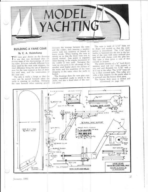
‘ | The vane is made of 3/16” balsa cut to shape and sanded so that the cross- increases the leverage between the vane er and the rudder, thus insuring a steadi course with less tendency to broach in By C. A. Heisterkamp section is streamlined. The 1/16″thedural botfeather is fastened into the slot at id glue heavy winds. When beating, the vane is swung up so that the dural vane arm is HE vane gear shown on the drawings is one that was developed after o> serving some of the shortcomings of exist: tom of the vane with some ambro sets. and held with clamps until the glue The vane is then given a coat of thin varnish or lacquer. The pintle consists of a ¥%,” hard drawn stainless steel rod 214” long pointed ata one end and threaded for 5/16” with 6-32 tap at the other. The 3/16” brass collar is then screwed tight. This collar pro-it vides a firm support for the pintle when is screwed into the bronze deck piece. The bronze deck piece is drilled and almost vertical. Less power is required when beating, as the angular movement of the rudder is very small. Swinging the vane up also gives it the advantage of the ing types. It is not radically different from those used by the west coast skippers, the chief difference being the use of duraluminum for the vane support in lieu of stain less steel wire, and the construction of e of steadier wind higher above the surfacvane the water and less possibility of the dragging in the water when the yacht is heeled. the vane arm. The drawings show the vane gear com: The arm is really a hinge so that the vane can be moved forward when the yacht is running or reaching. Swinging the vane forward when running greaily pletely assembled, ready to attach to the yacht, and also a detail sheet of the vari- (Continued on page 58) 6 x 32 7/8 3, BRASS TUBE } | l4 } SS STEEL 26 GAUGE 8 SSCREW eB ous parts. \A6~ RIVETS j-—— 2° —___4 SNUG FIT ON Wi6 TUBE ! ~—$<—$ 3— ——__—_—_TM \ ee IS CUT FROM ig SHEET BALSA 2 a : ( »> .| 3 j e pS 4 S PINTE,L RT ele PINTEL SUPPO a0 and’ * 4 tL e [=Ef rintm Ys DURAL FEATHER W G 1.0. HeBRASS a i ish 54 THREA slatih (; © Lelie, | @ 1. Ss. DECK LINE “HV tain oF dhe \ | — TUBE ;ig BRASS LEAD COUNTERWEIGHT = PIN ‘ BRASS VANE a ee ee + | . eee D ial — – Mg DURAL_ VANE SUPPORT é A i 6x 32 T tek Th THREADie= we 3x54SCREW YOUR2ALREQ’ANGLE “| BRASS ig RIVETS | 4 DURAL lgS stop |) ed January, 1941 ° ee x6 He | _/ – i” 461.a rig4g Wis BRASS COLLAR Ksy i A 2 x54 SCREWS4 |4 y er A-A [6 — VANE GEAR ASSEMBLED | RIVET & SOLDER : rt. f srass—olf —te— Ye BRASS TUBE 1 ic _ MODEL YACHT FOR 50-800VANECLASSGEAR RESIGNED & DRAWN BY CA.HEISTERKAMP nt as BUILDING A VANE GEAR pea SUCUUCUDUGS CSCC erUey mall] || OOOH VOQUAAATATTATTTUTATONTT aot
Meg good climb, ard in about ten seconds of motor duration, could really get up there. Powered with the “Super Atom,” the ship, though of the same heavy wing- mo loading, had a really sensational climb at about a 60 degree angle. The first few times you fly the special, you should use RAILROAD EQUI) New Construction YACHT NEWS (Continued from THE NEW HO PASSENGER COACH and New Needle-Bearing Passenge! CoachTruck Designed to exact scale from actu?! blueprints of the real car. Beautifully printed and embossed sides. Windows die-cut. Rivet details included. Authentic Penna. red with gold trim Fully assembled needle-bearing trucks with brass wheels insulated for 2-rail operation. Complete with trucks and liquids… . $1.95 (Trucks only no 30c. Assembled ic pr. HO FREIGHT CARS now (Less ‘irucks) 25¢ A complete variety of freight cars exact scale, precision-cut wood parts, highly detailed sides. NEEDLE-BEARING FREIGHT CAR TRUCKS with Insulated Brass Wheels. N.M.R.A. standards. Die-cast bolst»r and sides. attractive Easily assembled in a acighs (As. appearance. Easiest running. 5c sembled, per pair, 40c). Per pair TRACK SECTIONS | RUBBER ROADBED Shapes easily to curves. Makes a true, firm, realistic roadbed. |8” sections …. 25¢ SPECIAL RUBBER | !°sths .29¢ NYC, 2-8-0 Locomo-| tive, $57.75. 2-rail.] Brass construction. 16] other great types. | CARS with Cast Aluminum sides, ends and sills. Heavy, wonderful values at $2.75 up. CATALOG TO Dept. MC., Howard & Oxford 0 Pa. or 217 N. Desplaines St., Ghicago, Ill. Shop by Mail —and SAVE Moone. Ratwrono TQBIPMLOT BEB BACK of guarantee your on for immediate mail every DUNELLEN = DEPT NC Model is set in place However, the stop should be When tilted toward the The vane support is cut from 1/16” dural and the two side pieces shown in material on a radius to the lower hole. This pro- vides the the necessary motion in vane when more or less leverage is required. order. delivery MONEY purchase. D SHOP Railroadvers Since RELIEF model of the city of San Francisco, done ona scale of 1’ to 100’ was recently completed by WPA workers and is now being exhibited to audiences coming from all over the nation to the Golden Gate Exposition. The map, done in remarkable detail, is 41’ by 37’, and is so constructed that it is possible to re- move whole city blocks or whole sections to make any future changes or additions, thus making it easy to keep it up-to-date. The construction of a scale model of San Francisco was first contemplated by the City Planning Commission in 1937. A proposal for the project was submitted, approved by the WPA, and work started early in 1938. The City Planning Commission requested the model to be con: structed primarily for use in city planning studies, dealing with re-zoning, rebuilding, new highway development, etc. It is necessary to use a relief map, or model, in order to show visually and topography, natural the realistically, street grades, the general proportions and sizes of building and lots, and the phy: sical relationship of the various parts of the city to each other and to surrounding areas. The growth of San Francisco was westward from the docking and anchorage facilities of the harbor, and the business and heavy industry reaching out along the lowlands and valleys, the residential construction taking place largely on the adjacent hillsides. In predicting the trend of future devel: opment in by business, two 1/16″ rivets. Small angles are San Francisco—extensions of industrial and residential areas riveted to each end of the cut out portion —it will always be necessary to pay great and 144”—3×54 round head brass screws with locknuts set in the vertical leg. These attention screws provide the necessary adjustment when trimming the yacht for windward sailing to a piece of brass filed to fit the friction which piece. to the has This friction to the physiography of the ground because of its great influence on natural growth. In such planning, the relief map is of the greatest aid because, to the laymen and to many engineers, a contour map does not present the necessary all-inclusive picture of ground forma: tions. Other city departments may well refer to this model at times during plan: ning discussions. The model would piece. furnish an ideal medium for visual pre: The lead counterweight is made by boring a 1” hole %4” deep in a block of wood sentation and streets, pouring in melted lead. This lead plan, of any including proposed the over-passes marking and unit of traffic one-way over-head drives, is drilled for the brass bushing thru which cutting through blocks, etc. a 1/16” pin has been fastened to act as a guide and stop. After the lead has been In order to show the routes of the main highways entering San Francisco, it mounted on the tube, a 1/16” brass pin is fastened at the end of the tube to pro- Mateo vide a stop. from the city and county line. The entire vane gear is mounted NEW JERSEY In Relief Model Of Entire City The vane lever arm is cut from 1/16” dural and fastened to the brass bushing assembly is then soldered Sie MODEL RAILRO: “Serving stop vane, the bottom should be below the level of the adjustable screws, so that when the vane is movec the stop will rest against the adjusting screw heads. been Send a dime today for your copy. Now 32 big 8%4×11” pages of bargains. Over two STOCK dural moved. soldered CoPPeiEs 1841 canes thousand items described and priced, and all IN small The brass tube which supports the lead counterweight is slotted, then riveted and Mailing receipt that fits snug to and riveted to the arm. These side pieces provide the support for the vane. A slotted hole is cut in the bottom section SEND 10c FOR carried are fastened is made of 26 gauge stainless steel bent to shape. The part over the tube should be very Section A-A are from the same HUNTINGTON, INI). upon by means of two countersunk rivets. The friction piece to which the dural vane support and counterweight support easily (A Megow Plant) Catalog dural lever arm is fastened to this bushing with a rivet. Manufactured by I rudder. The deck piece is fastened by means of three 14” #1 brass flat head wood screws. The brass tube to which the yane lever arm is fastened should be an easy fit over the pintle. One end of the tube is tapped with a 6×32 thread, and the stainless steel screw with the cup point is screwed up tight. The %” brass bushing is soldered to the other end of the tube, and the The SCALE MODEL RAILWAYS, Inc. 1941 tapped as shown to provide various ratios of lever arm between the vane and the action of the wind. 4 ‘ O-GAUGE NEW page 27) prevent the vane from slipping due to the CEMENT for laying Track Sections and Rubber Roadbed . 10c It is very im- used with the Braine gear. portant that the rudder action be very free. Many shippers using the vane gear balance the rudder tube between two needle point bearings. your motor at about half throttle. ELLAMMROR RMN Brass rail accurately held to correct gauge. 18” row rudder in lieu of the longer rudders well aft on the yacht about 2” forward of the transom ending. The ratio between the vane and the rudder should not be less than one to one. The writer has found a ratio of 3 to 2 works better. Best results have been obtained by using a deep nar- was decided The to include County—about model measuring 41’ is set some of San 7,000 feet south upon east-and-west a and platform 37 1/3’ north-and-south. The platform, being of a “knock-down” design, can be taken apart or assembled in a short time. This to model is at a scale of one inch 100 feet, horizontal and vertical, con:


