- Plank-On-Frame Construction for Model Yachts, Part 2. By C. H. Farley.
- Continuation of the series on plank-on-frame construction, focusing on the backbone and alignment.

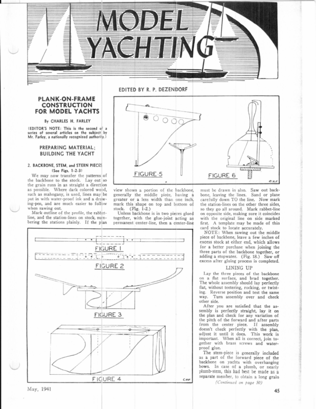
TT LIU i TUUTUCTTTT PCr TT] i | TH PLANK-ON-FRAME CONSTRUCTION FOR MODEL YACHTS ®O O0Q en 7, By CHARLES H. FARLEY (EDITOR’S NOTE: This is the second o° a rf /| series of several articles on the subject by Mr. Farley, a nationally recognized authority.) PREPARING MATERIAL; / BUILDING THE YACHT 2. BACKBONE, STEM, and STERN PIECES (See Figs. 1-2-3) FIGURE-5 We may now transfer the patterns of the backbone to the stock. Lay out so the grain runs in as straight a direction as possible. Where dark colored wond, 6 FIGURE view shows a portion of the backbone, ing-pen, and are much mark this shape on top and bottom of Mark outline of the profile, the rabbetline, and the station-lines on stock, numnbering the stations plainly. If the plan the middle piece, greater or a less width than having ==-== ade ene As {– a one inch, stock. (Fig. 1-2.) Unless backbone is in two pieces glued together, with the glue-joint acting as permanent center-line, then a center-line must be drawn in also. Saw out backbone, leaving the lines. Sand or plane carefully down TO the line. Now mark the station-lines on the other three sides, so they go all around. Mark rabbet-line on opposite side, making sure it coincides with the original line on side marked first. A template may be made of thin card stock to locate accurately. NOTE: When sawing out the middle piece of backbone, leave a few inches of excess stock at either end, which allows for a better purchase when joining the | (GURE [== : CHF generally when sawing out. 4 rT such as mahogany, is used, lines may be put in with water-proof ink and a draweasier to follow \ three parts of the backbone together, or adding a stopwater. (Fig. 18.) Saw off excess after gluing process is completed. ee a LINING UP Lay the three pieces of the backbone on a flat surface, and brad _ together. The whole assembly should lay perfectly flat, without teetering, rocking, or twisting. Reverse position and test the same way. Turn assembly over and check other side. After you are satisfied that the assembly is perfectly straight, lay it on the plan and check for any variation of the pitch of the forward and after parts from the center piece. If assembly doesn’t check perfectly with the plan, adjust it until it does. This work is important. gether with When all is correct, join tobrass screws and water- proof glue. The stem-piece is generally included as a part of the forward piece of the backbone on yachts with overhanging bows. In case of a plumb, or nearly plumb-stem, this had best be made as a 4 FIGURE May, 1941 CWE separate member, to obtain a long grain (Continued on page 50) 45
also place the ends of the upper pieces in the notches in S6. We can now finish up the front of the boat by putting in the front sections of the lower longitudinal members and also the top members. This should complete the frame work. De not forget to drill the four holes in the motor bed Use a metal template for doing this as you will need it later for drilling the dural angle motor supports. We are now ready to start the covering. For this size of hull, 3/64”, three ply mahogany is suitable. First make cardboard templates of the sides, STREAMLINER DOOLING Employing and new original will principles which enanle wer to run 5 to 15 M.P.H. faster with )our resent Motor. ow Spur Gear Drive, mounted with finest »all bearings rinciple ‘lew drive shaft entirely). over-all reduces mounting, (eliminating motor of height of car to 4%”. New higher gear ratio s/ock equipment. New two-piece body design of hivhly Weight bare under 3% \bs. polished aluminum. Parts easily accessible and visible for inspection. Car also has a special Breaking Record all This scientific design flywheel included. Get your order In the mail immediately and be the first in your club to put out some real and exciting speeds. | Other Choice Cars Made Popular by Puolic Demand— Dooling: Front: Dive: cciiccue cesses ver § 2).50 peeing Rear Drive ………….0.00005 2.50 New Bremer Whirlwind ……………. 1.50 RROMNOR ALTON oases eseieecessare araarawiaaare oer 2°.50 1941 Rexner Deluxe ……………….. 2).50 Mathews Achiever ………. yf exatate aiaiecareiavere 24. jJass ‘‘A’’ Peerless No. | ………….. 15.00 Famous Demanded Motors!!! Dennymite Airstream Engine ………… 17.85 Record Breaking Hornet ……………. 3° .00 New “OK” Tornado …………..22055 Ohlsson ‘60 22… eee ee ee eee 2′.50 Choose your combination today and be a Wirner deck, and bottom. The bottom will be in four (4) pieces, front (plane) in two (2) edges the I Chicago, pieces can are 4%” be and trimmed screwed find it is best to rear around and put the off after cemented the bottom cockpit opening; this outline on the plywood also. mark When cutting out the opening, save the waste piece for the hatch cover. This can be BILL OF MATERIALS 1 piece 3/64” mahogany plywood 36” x 36”, for covering. 1 piece ¥5” 3 ply birch; 12” x 18”, for frames S1 to S6. Ill. 1 piece 14” 3 ply birch; 8” x 16”, for motorbed. spruce; 8 2 LACQUERED 1 ! Orders filled in will and stem-piece, and must attached to piece 3%” plate 6” drill rod x 6” 36” drill the be backbone AFTER the “lining-up” process is completed. The transom has to be worked down to shape out of a solid block of The rabbet may be cut either before the backbone is finally joined together, or in sections, taken apart for convenience in handling. On small boats it is hardly necessary to cut separately, however. or there is apt to be a difference in the 4” shape of the boat, adjacent to the back- bone, particularly in the garboard section. Fit the stern-piece and cut rabbet, unless the planking is carried right out to the end of the yacht, flush with the after face of the stern piece, which method is easier, but not so ship-shape x as using a rabbet. long, This article, with photos and drawings, will continue in the June Model Craftsman. long, rod, about THE CAR BARN (Continued from page 41) turn 1 drawing board—18” smooth and flat. % long, MATTHEWS pound finishing x rear the opening car weighs a 24”, Screw and cement it support to the deck. Luxury cars were little over 48,000 pounds. After the equipment was purchased by the L.V.T., the rear section was made luxurious by the installation of over- nails—114” to the They are constructed of aluminum and to give the maximum strength and the minimum dead weight. Each for forming board. of to These steel set in flush by running a 14” piece around the attention themselves. built by the Cincinnati Car Company for the Cincinnati and Lake Erie. 2 or 3 sheets of Garnet paper about 7/0. 1 piece of 12” x 34” x 36” long shelving, for forming board. | your Liners —#0—#00. be FOUNDRY screws Y% pint Bakelite base-varnish. 2 or 3 sheets of sandpaper #1 rotation. 2228 Railroad Ave., Fresno, Calif fitted 1 piece 14” x 2” x 12” long pine, ……. $32.00 LACQUERED ACHIEVER with De Luxe drive ..$35.00 backbone and for keel. with ACHIEVER hd. sliding fit on 4%” 5/32” o.s.dia. adaptable with standard drive ..$32.00 ender,” is usually much wider than the Be careful and cut the rabbet-line as near as possible ALIKE on BOTH sides, %” for propeller strut. for propeller shaft. 1 tube Ambroid Cement. 1 piece brass tubing—6” SILVER ACHIEVER with standard drive ……. $29.00 De Luxe drive #6—32 Fil. 1 piece brass 1/32” thick. carries FIVE ballhas an_ adjustable ACHIEVER screws brass wood screws for strut plate. to many other makes of cars, and can be purchased separately, or in an ACHIEVER. SILVER hd. 3 gross #0—’4” long—flat head $16.00 is transom, unless in the case of a “double or vice versa. It is best to leave this junction uncut until this point is reached during the process of planking, when it will be more readily understandable. brass wood screws. 1 doz. #0—3%” long—flat head SENSATIONAL unit Fil. for motor support. long, NEW The #6—32 long, DIF ERENT | unit and piece, “fashion piece,” or where the angle quickly shifts from an almost horizontal cut to a vertical one, longi- 1 piece 34” x 1” x 6” dural angle shaft. (Fig. 20.) The stern A jack-knife and an ordinary flat chisel may be used to cut the rabbet, but the author finds that small chisels, ground to a “skew” (Fig. 19) are best, as they will cut in any direction of grain readily. Also a small rabbet-plane is useful in getting a well-faired “landing.” You will probably find a place where the rabbet-line takes a twist, at a spot 1 piece 2” x 34” x 4” pine wood, for nose block. —motor support. pinion in the wood. 3. CUTTING THE RABBET the 2 pieces 14” sq. spruce; step reinforcement. This new bearings, (Continued from page 45) stock. out 4 pieces 1s” eq. tudinal members. Matthews proudly announces the DE LUXE DRIVE UNIT MODEL YACHTING mark TROST Model Shop W. 63rd Street, which section, about (This article will be concluded in the June Move. CraFrtsMAN.) pieces on first, then the sides, and finally the deck. In making the deck template, products. 3111 middle Leave into place. tomorrow. We are one of the greatest Model Iiace Car Suppliers in America therefore you can 2 assured of prompt service and only quality prov- ing pieces, plane. line fastening. emus , FEF members. power plant, propeller shaft, strut, and cr Prompt Deliveries to all Points ki “O 87 M.P.H. STREAMLINER Now in Middlewest The last thing to do before finishing the hull is to glue the nose block in place Sand paper the and carve to shape. entire hull thoroughly with fine sandpaper, and we are ready to install the t+ WORLD’S RECORD it. stuffed chairs and divans. So popular have the cars become that the trips are often made in two sections. Numbers 1600 to 1008 have Westinghouse motors. All trolleys have two kinds of When writing to advertisers please mention Move. CrartsMAN for May, 1941


