Main Sheet: Our online editor takes the mystery out of carving your own mast

By Don Plough

This article was published in Model Builder, Vol 4, No 28, March 1974.

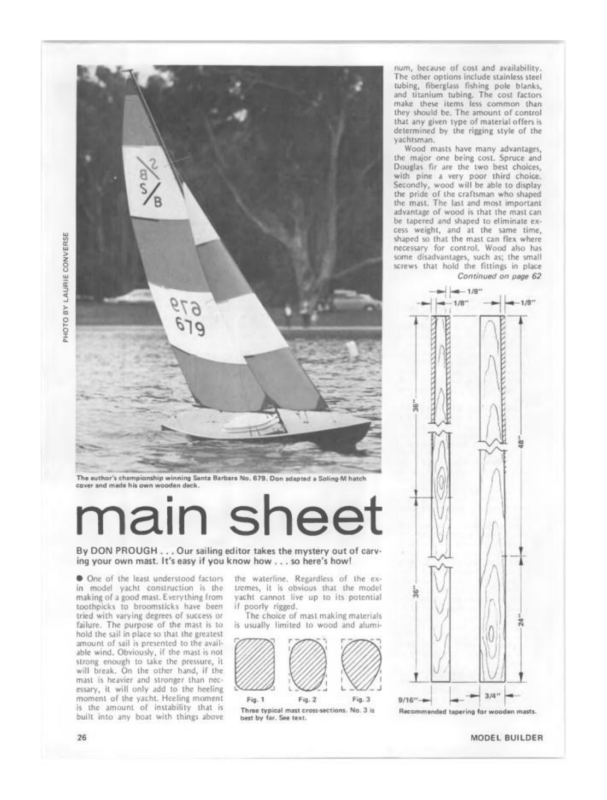
One of the least understood factors in model yacht construction is the making of a good mast. Everything from toothpicks to broomsticks has been tried, with varying degrees of success or failure. The purpose of the mast is to hold the sail in place so that the greatest amount of sail is presented to the available wind. Obviously, if the mast is not strong enough to take the pressure, it will break. On the other hand, if the mast is heavier and stronger than necessary, it will only add to the heeling moment of the yacht. Heeling moment is the amount of instability that is built into any boat with weight above the waterline. Regardless of these extremes, it is obvious that a model yacht cannot live up to its potential if it is poorly rigged.

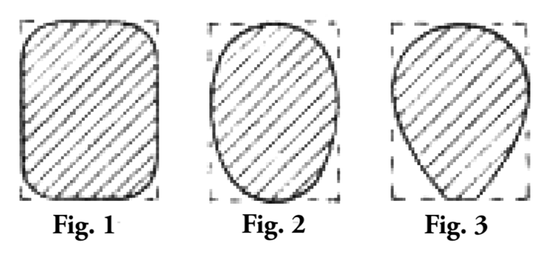
Three typical mast cross-sections. Fig. 3 is best by far. See text.

The choice of mast-making materials is usually limited to wood and aluminum because of cost and availability. Other options include stainless steel tubing, fiberglass fishing pole blanks, and titanium tubing. Cost factors make these items less common than they should be. The amount of control that any given type of material offers is determined by the rigging style of the yachtsman.

Wood masts have many advantages, the major one being cost. Spruce and Douglas fir are the two best choices, with pine a very poor third choice. Secondly, wood allows the craftsman to display pride in shaping the mast. The last and most important advantage of wood is that the mast can be tapered and shaped to eliminate excess weight, while at the same time allowing controlled flexibility where needed. Wood also has some disadvantages. The small screws that hold fittings in place can pull out, or worse, split the mast during installation. Another disadvantage is that it takes a great deal of time to properly shape and finish a good mast.

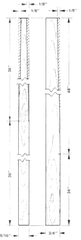
The first step in making a wood mast is to select a clear (no knots) piece of wood with straight grain. Next, trim it to size for length and cross-section. For example, a 72-inch mast should be 3/4 x 9/16 inches, and a 60-inch mast should be 1/2 x 3/8 inches.

The next step is to determine the shape of the mast and the taper from top to bottom. For simplicity, the 72-inch mast will be used for examples. Figures 1, 2, and 3 show the most common styles of wooden masts. Number 1 is not only poor looking, but will not allow air to flow smoothly along the sides of the mast. Number 2 is much better, but not as effective as Number 3. The reason for the flat backside on Number 3 is to attach the jack wire, which holds the sail next to the mast.

Once you have selected the Number 3 type mast, scribe or pencil in a set of lines to mark the width of the jack wire table on the back (aft) side of the mast. The so-called “table” is usually 1/8 inch wide. Make a corresponding set of marks down the front (fore) side of the mast, as these lines will also be used for shaping.

On the side of the mast, about two-thirds of the way down from the top, make a mark at the front or leading edge. Draw a line from this point to a mark that is one-eighth of an inch back from the front edge at the top. Carefully plane off this section. Then redraw the double line on the front.

Using the same method as above, remove from each side a tapered section from halfway down the mast to the top. The amount to be removed at the top on each side is 1/8 inch.

Let’s double-check what has been done so far. The top of the mast should now measure 1/2 x 7/16 inch.

The next step is to mark the sides of the mast with lines to guide you in trimming the rest of the mast down to the proper size and shape. Time and workmanship really show at this point.

As a tip for rounding off the sharp corners, use a piece of 2 x 4 wood about 8 inches long as a sanding and shaping block. Bring the wood down to a smooth finish with 180-grit aluminum oxide paper and check for straightness. If all is well, finish sanding with 320-grit paper. Then apply your preferred wood finishing material, such as clear epoxy, varnish, or a clear urethane coating.

The spreaders should be attached to the mast about 28 to 30 inches up from the base. The lowers are also attached at the same point as the spreaders, and the attachment for the top diamond supports should be 19 to 20 inches down from the top. Drill a 1/8-inch hole through the mast and use 1/8-inch brass rod to form the support for the tubing that will serve as the spreaders and the diamonds. Next time we will discuss how to attach rigging wire, fittings, and other hardware.

main sheet By DON PROUGH… .Our sailing editor takes the mystery out of carv: ing your own mast. It’s easy if you know how. ..so here’s how! © One in of the least unders model yacht the construc raking of 2 good mast Everything from footnpicks fo waterine. tremes, broomsticks have been yacht cannot if poory Regardless its obvious lve up of the ex thatthe model to its potental rigged tied with varying degrees of success ot The choice of mast making materials failure. The purpose of the masts is usually Imited to wood and alum hold the sil place so that the greatest mount of sil s presented tothe aval ‘ble wind. Obviously, tthe mast snot Strong enough will Break, mast ssa, On take the pressure, it the other hand, if the is heavier and stronger than nec it will oly add to the heeing ‘moment of the to the yacht Heeling moment amount of instability that Is built into any boat with things above 2% bet byes Seetexts wel Lf MODEL BUILDER however, some rationalizers have risen to defend TV a5 serving 35 an actual REPLICA OLD TIMERS INSPIRATION fo modeling. They point Aurwenic scALING.~ MACHINE CUT PARTS FREE FLIGHT ~ RUDDER ONLY R/C fut that old. aviation flcks ate fre fuently shown on Iatedate rns, and Suggest examining TV fogs for descrip. \Goabar’s 1940 Silane TSE ae anon tions of forthcoming offerings. Some of these are admittedly real “bombs” from plot standpoint, but sometimes feature fare and exciting ateraft guaranteed to Suri’s 1940 16 Rar make you reach for your Sview calle HST Es in “The Flying Aces Club of Connecticut Ist of has even Suggested compiling. ‘ld movies which contain fying scenes, Since thee tiles do not always furnish MICRO MODELS 0.808 173 that srt of elu. ‘Current fare also. shown signs of aviation influence every now and then. Helicopters and lighilanes are common on shootemup series, a ate “props airports. Then. too, in Turned up. hangeligess have such’ unlikely places 36 Soap commercials and M.AS.H. One of the boys in “THE. ‘model airplane nut, Frequently shown WALTONS” is. 2 and his efforts ae for a microecond for two. Even Sanford and Son can be Seem loading what appears to be an old tailplane Ch “omens ef A ea Sl into their funk wuck at the fend of the show! KEEPING TRACK Model builders seem common malady… to suffer a a short attention Span. Thus we find we can seccely com Plete one project before 2 more interes fing. one comes along to distract one’s partment. Materials required to furnish {he inside are, for the most part, Inex- carefully avoided. Probably the best way to assure a clean appearance Ts 10 best intentions. Bill Krecek has gone 40 Ingredient, wil then require very Title, if any ad pensive and estily obtainable. The secret TIME. turns out to be It satistying ceslts are 10 be hieved, ss wal, sufficient hours must be de- contemplate: oted to the tak, A few guidelines to keep track of all hscurren activites. The forms have categories for hesive- As an example, the contol sick Peanuts, Indoor, can, in some cases, extend through the floorboard and be glued on the under: side only, thereby presenting an abso 1. All balsa wood inthe cockpit area which wil be visible to a viewer sould luely glue-free junction as seen from the top. balsa sve method of instaling components Tor covering intron wall ad floor If the comed variety 1s employed fueh everything “ied down’ inthe. ovent orang. Remember, the quality of of Daint wl be required, 8 compared to than berpainted or covered, Otherwise, twill Took exactly ike what itis wood, Panfed paper one approach Ths. combination mechanicalladhe us the. added. advantage of keeping Tar more important ST pagtsine conde nuctl, vey ie eDekoithedeal quant Eommon typing or wrtingtablet stock, 2: If pins ae used to represent knobs, AEROBATIC. SEAGULL BY, MARK SMITH ROUTINES tite, tes they wil tok exactly ike pi Those lem ean be ed a} We ate supplying the above wll of ou fad desewed ee ine for any Be sutably modified Sehey wil more neatly resemble the intended pans, Wile on the subject, pins afe aso. a Livingston Seagull “sine he producers, for reasons best Known to thems, went out of their way Lo omit this im the BASIS Of interior deals, but should oor, Simulation for” ret and are Soul rosly vera for that pur os 3: whenever feasible, the cockpit components shouldbe painted PRIOR to “bsembly. Trying. to paint adder pedals ara tch wih along hin bth Ser aembly, sot conducive “0 nesiness (or tanguity) “4 Expos glue jtnts should be far as to draw up charts, in order 10 mechanically fasten the details, which ef who muy sex_the fm “onathon portant information. Rest sued tat Mark ‘Smith of Escondio, Calor, {abated AND flew the model segul for the aerobatic and dive sequences that appeared inthe fim. Just watch e wigs bid with “st” forth BACK TO THE BOOB TUBE Tae wat when the teleyon set was regatded zone ofthe worst det ments {oa model buder’s ouput.Now, ROW. etc. Jumbo, constuction COp, Gas, Alongside each divion is 2 checkoft space indicating the status OF every project, such as. Proposed, Ready to-fnish, Needing. Repair, and Ready. Newdless 10 say, most of us would haye’a lot of blank spac inthe “ready”TM Column, but 2 definitly crowded con tition tn the “proposed” area! iMain Sheet. Continued from page 25 an pull out, ‘mast or even worse, spt the “while ‘being. installed. Another Gsadvantage i that it takes.a great deal fof time to properly shape and finish 2 good mast. Fist step in making a wood mast is to select 2 clear (no knots) piece of Wwood with straight grain. Next, trim itt slee for tength and crosssection AAs an example, 472 inch mast should be 3/4” x 9/16 inches anda 60 inch ‘ast should be 1/2 x 3/8. The next step is 10 determine the shape of the mas and the taper from {op to bottom. For simplieity, the 72 inh ‘mast will be used Tor examples Figures 1, 2, and 3. show the most common styles of masts feud in wood. Number 1’s not only poor looking but will not allow the ai to flow smoothly MODEL BUILOER yew! RETRACT POWER SYSTEM FOR 4-CHANNEL FLYERS! POWERFUL NEW SERVO, SPECIAL SWITCHING SYSTEM AND 2-CELL 3ATTERY PACK— WIRED UP READY TO INSTALL. LIGHT! COMPACT! At last! A way for 4-Channel flyers to easily ‘get into retracts. Our new power system is ready to go – just add 2 penlite cells, mount the trim-switch on your throttle servo, connect the retracts and that’s i! When your throttle ono) SN uartety 6x and trim levers are both moved all the way up or all the way down, your retracts will do the same! Servo has ample power, easily handles tri-geor operation. RETRACT POWER SYSTEM RPS-1 ong the sides of the mast, Number 25, much better, but not 26 effective 35 Number 3. The reason forthe fat back 2 Side on Number 3 f blocky and Write, to attach the jack which holds the sll next to the tip about rounding off the sharp oeners use a piece of 2x 4.x 8 inch ong pine fora sanding and shaping down’ to. 3 type mast, scribe or pencil int set ‘or Tines to. mark the width of the jack Wire table on the back (aft) side of the mast. The so-called table is osually 1/8 Inch wide. Make a corresponding set of marks down the front (fore) sie ofthe mast, 3s those Ties will a0 be ied for shaping. ‘On the side of the mast, wo thirds down from the top, make a mark atthe ‘oxide paper and Your favorite wood fnhing material Such as Superpoxy clear, varnish, or 2 leat urethane. paint “The spreaders should be attached to the mast about 28 to 30 inches up from the base. The lowers are also attiched. atthe “same” point 38. the Spreaders, and the attachment forthe top diamond supports should be 19 10 118 inch hole through the mast and use inches down from the top, Drill 1/8 brass vod to form the support for the tubing that will be the spreaders and the diamonds. Next time we will plane ‘off this section. Now redraw the double line on the from. Using. the same method a above tings nd special gadgets, remove fom each side a apered section from half way down the mast t0 the Counter… done $0 far. The top ofthe mast should dlecuss how to attach rising wire, Fi ° Speed! Trophies for ist, 2nd, and 3rd lace «record or nok. All Al and ‘AMA ries wil ply. Sponsors include: Kraft Systeme, For the Linde size and shape. Zoli sand off scale it. the famous Bowing’Stearman Model 78. Decals and Island Hobbyerafts I, Inc, Astro Soarerat, Airron Marks Models, Dumas Products, Hobby Lobby, Wiliams Bros, RCM, Cross Gay Blvd, Broad Channel N.Y. 11693 has announced is latest Nick MARCH 1974 Dries forthe fastest, record-breaking ies, “What’s printed bala, Dad?” “Get back 10 your Super Kaos, tell you later!” [Next step 10 mark the sides of the mast with lines to glde you in trimming the rest of the mast down tothe proper Time and workmanship ford trials Apri 6 and 7.13 and 14 {nd 20 and’ 23. A’7,000 dollars in RS. Systems, quality printed balsa Long The Torrey Pines Gulls will host 3 weekends of RUC glider speed ree Continued trom page 6 ‘pow measure 1/2 x 7/16 inch, realy show up at this point To give you SPEED ATTEMPT for 20 The amount tobe removed at the WORLD Straghtnes, I alls well, finish sanding ‘with some 320 rit paper Then use font of leading edge. Draw a tine fom top on each side i 1/8 of an Inch Let’s double check what has been GLIDER RECORD 180 grit check this toa mark that i one eighth of an inch back from the front edge of the ‘mast at the top. Now very carefully top. WIE have at it. Bring the wood nice finish with Sluminum ‘Once you have selected the Number $29.95, 722 more’ information, contact registrar: Hop 7880 Ceminito Glorte San Diego, Cal, 92122, or, The Torrey Pines Gulls P.O. Box 1568 La olla Cal, 92037 6