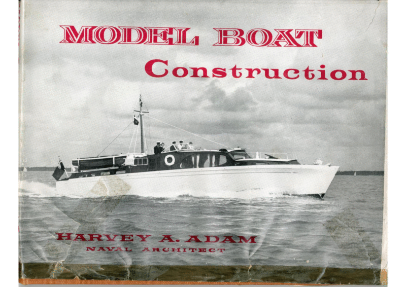
Model Boat Construction by Harvey A. Adam – 1952

This book is primarily intended as an aid for the newcomer to model boat building. In taking the stage by stage construction of a typical model power boat, from the drawing board to completion, the book intends to present the fundamental principals of model boat building so that the novice will have no difficulty in constructing any of the models which have been dealt with in detail in the latter part. It is also presented to the experienced modeller as a reference book and as a summary of the author’s own model boat building experience during the last 25 years, and while some of the methods described are not new, their adoption has been the result ofa constant striving for simplicity and ease in the construction of working scale model boats.

  • Chapter One: General Discussion
  • Chapter Two: Choice of Materials
  • Chapter Three: Metal Fittings
  • Chapter Four: Engine Bearers, Exhaust Systems, Fuel Tanks, Couplings
  • Chapter Five: Propellers, “P” Brackets, Rudders, Simple Steering Device
  • Chapter Six: Scales, Drawing Instruments, Transfer of Drawings, Power Units, Construction of a Typical Model Motor Cruiser
  • Chapter Seven: Painting and Finishing Model Boats
  • Chapter Eight: A 16-in Sharpie
  • Chapter Nine: An 18-in Clinker-Built Dinghy
  • Chapter Ten: A 20-in Ventnor-Type Hydroplane
  • Chapter Eleven: A 30-in Cabin Cruiser and 30′ Runabout
  • Chapter Twelve: 71-ft 6-in British Power Boat M.T.B. and 80-ft Elco P.T. Boat
  • Chapter Thirteen: Navigation and Sailing of Model Boats
MOIDEI, BOW Construction | A”syJ“oIaYiDw|m,Ng MODEL BOAT CONSTRUCTION by Harvey A. Adam (Naval Architect) PERCIVAL MARSHALL LONDON 1952 Copyright 1452 by Percival Made and printed in Great Britain by Barnicotts Limited, Priory Bridge Road, in Street, London. W.C,2. Canadian Office, British Book Shop, 122, East 263-284, 35th Street, Marshall & Co. Led Taunton, Somerset for Percival Marshall and Company Limited, 23 Great Adelaide Street West Toronto. New York, 22. United States Office, British Book Centrz, ce To my Wife cB) FOREWORD From Sir Robert Bland Bird Bt., M.R.1. DurinGa recent conversation with Mr. Winston Churchill, he remarked to me, he thought that everyone whose vocation was the ‘‘stress and strain’? of public life, would be wise, as the years advanced, to try and train their hands. “But that is just what I have been doing,’’ was my reply. “Since retirement ended my 24 years in the House of Commons, my hands have been teaching themselves how to build and sail model boats of many kinds; in particular high speed sea-going model power boats.”” Mr. Churchill’s eyes shone brightly, as he said: ‘* That must be grand fun! ”’ No words could be more true, for indeed it is thrilling fun to see one’s home made craft running free and heeling over, before a stiff breeze; or, being power propelled, braving gallantly head on, the waves of a stretch of choppy water. Believe me, all these delights are within the reach of anyone who reads profitably this book. Out of the wealth of his knowledge and experience, Mr. Harvey Adam has helped me generously, and I am grateful to him for *‘ My Joy of the Water’. ROBERT BIRD The White House Solihull Warwickshire vii INTRODUCTION Vice- Admiral Sir Thomas Tower, K.B.E. Wuen I open a book and I find it has an introduction | experience a slight feeling of irrit- ation. One wants to read the book ; what then is this introduction? Shall I read it or not ? Generally one feels more or less bound to glance at it at least, just on the chance that there may be something in it. If these feelings are shared, the obvious thing to do in writing an introduction is to make it short, and I will certainly do this. boats. This book tells you all about the design and construction of all sorts of sea-going model It has been written by a man who perhaps knows as much about the subject as anyone, and what he says he has learnt from practical experience at sea. Of course there is the basic theory, but all theoretical data has been put to the test of practical experience in all sorts of weather, and it is this fact which, to my mind, makes this book of such value. If one has any interest in such matters, this book will give just that information which will guide one in the vital difference between a right and a wrong boat. | And when one sees the astonishing looking craft that are afloat today, what a difference this knowledge could make. There is an old saying that if a ship looks right she is right, and the converse is certainly true. And, of course, the word ‘ right ’ includes most definitely efficiency as well as appearance. Among the various vessels discussed in this book are two types of British and American Motor Torpedo Boats, and these vessels, which in 1939 were in an early state of development, came into their own in World War Il. and played a great part in their own sphere. I happened to be Vice-Controller at the Admiralty for the greater part of that war and one of my duties was to provide as many of these craft as were required. It is no doubt for this reason that the author, himself closely connected with the production and trials of these vessels in the war, has asked me to write this introduction. and Iam quite certain that readers will I am indeed honoured to do so, find the contents of this book most interesting and instructive, and thereby enabling them to appreciate the intricacies involved. able to understand the different factors which are important, to bring a new eye to bear on the different craft they may observe afloat. and They will be will be able Beyond all this the wider knowledge which such a book can give should mark a definite forward step in the design and performance of model boats of all kinds. Incidentally there is a lot of fun to be got out of making model boats by the methods recommended by Mr. Adam. _ I know this from personal experience. ACKNOWLEDGEMENTS THE author wishes to acknowledge with grateful thanks the assistance given him in compiling this book :— The Elco Naval Division of the Electric Boat Company of Bayonne. N.J. for the drawings and photographs of the American P.T. Boats. Nettlefold & Sons Ltd. of London for their drawings of screws, fixings, etc. Ratsey & Lapthorne Ltd. of Cowes, I of W, for the suits of sails on the Sharpie and Dinghy models. Vosper Ltd. of Portsmouth for the drawings and photographs of Triton II. And to Mr B. E. Cook of Hemel Hempstead and Mr R. A. Redhead of Associated Newspapers Ltd. for permission to reproduce photographs of their model Motor Torpedo Boats. Other photographs by Messrs James H. Smith of Totton, Edward Mudge & Sons of Fawley, and Phillips, Photographers, Southampton. xi CONTENTS Page FoREWoRD vii INTRODUCTION ACKNOWLEDGMENTS xi Cuapter One—General Discussion Carter Two—Choice of Materials CuapTEeR Two—Meral Fittings CHapTER Four—Engine Bearers, Exhaust Systems, Fuel Tanks, CHAPTER Five—Propellers, “ P”” Brackets, CHAPTER Six—Scales, Drawing Instruments, Model Motor Cruiser, Couplings Rudders, Simple Steering Device Transfer of Drawings, Power Units, Construction of a Typical 23 CHAPTER SevEN—Painting and Finishing Model Boats 36 CHapTER Etcut—A 16″ Sharpie 38 CHAPTER Nixe—An 18” Clinker-buile Dinghy CHAPTER TeN—A 20” Ventnor Type Hydroplane Carter Eteven—A 30” Cabin Cruiser and 30’ Runabout CHAPTER Twetve—jr’ 6” British Power BoatM.T.B. and 80’ Elco P.T. Boat 68 CHAPTER TuirteeN—Navigation and Sailing of Model Boats 97 Plates The author with some of his fleet fromispiece Elco Patrol Torpedo Boat in banking turn 30” Runabout H.M.S. Furious at full speed Model ship at full speed 55’ Motor Cruiser Triton If 40” Model P.T. Boat No. 603 25″ Racing Hydroplane 10 ¢.c. Westbury Twin in 30” Runabout Hull Triton II 16” Sailing Model Sharpie 18” Clinker-built model Dinghy 44 25” Racing Hydroplane for 2c.c. diesel engines 52 30” Fast Cabin Cruiser designed for Mills diesel 56 Keel Assembly 58 After end of framed up hull 58 Framed up hull before bevelling 58 LIST OF PLATES—continued Framed up hull after bevelling Overlap at forward end of topside planks Method of marking bottom plank overlap Completely planked hull Hull turned over and ready for upper works Cabin bulkheads and stiffeners fitted 63 Cabin sides and cockpit fitted 63 Wheelhouse, cabin front, and decks fitted 63 Open Sports Runabout in rough seas 64 Scale model Motor Torpedo Boat and American P.T, Boat 67 Scale model M.T.B. 465 at 14. knots 68 Scale Model M.G.B. 77 69 . 40” Model of American 80’ Elco P.T. Boat American Elo P.T. Boat at 43 Knots Xvi 63 jo je Scale model of M.T.B. 465 je Model M.T.B. built by Mr. B. E. Cook, Hemel Hempstead. jo The author launching his radio controlled cabin. cruiser 73 M.T.B. 488 at speed in Southampton Water 14 Model P.T. Boat 603 on automatic control 74 16” Sharpie at the Salternes, Lymington 74 LIST OF PLATES—continued 38. Cooling fan and louvres on 30” Speedboat Hull 77 39- Mr. Cook’s M.T.B. showing deck equipment 77 36” Vosper M.T.B. Hull with radio equipment 78 47” Motor Cruiser Fairlie Bluff under radio control 81 42: 3 c.c. Delmo Diesel Engined R.C. Test Hull 87 43. Mr. R. A. Redhead’s Radio Controlled P.T. model 89 35” Scale Model British Power Boat M.T.B. 86 40. 45. 47” Motor Cruiser Fairlie Bluff 46. 47’ Prototype on which Fairlie Bluff was modelled Full List of Drawings will be found after the Index 92 102 XVil CHAPTER ONE: THIS book is primarily intended as an aid for the newcomer to model boat building. In taking the stage by stage construction of a typical model power boat, from the drawing board to comple- tion, the book intends to present the fundamental principals of model boat building so that the novice will have no difficulty in constructing any of the models which have been dealt with in detail in the latter part. Itisalso presented to the experienced modeller as a reference book and as a summary of the author’s own model boat building experience during the last 25 years, and while some of the methods described are not new, their adoption has been the result of a constant striving for simplicity and ease in the construction of working scale model boats. Although today it is rare to find a modeller carving his boat in the old ‘‘ dug-out ”? manner from the solid block, this tricky and difficult method was almost universal when the author first became interested in models, and it was seeing a friend in 1919 thrust his gouge through the bottom of his beautifully ‘‘ dug-out ’? model of a Coastal Motor Boat that convinced the author that the obvious and best way of constructing model boats was to adopt, as far as possible, full size principals. Putting this theory to the test the author’s first model was a 24” replica of the 1913 winner General Discussion of the American Gold Cup race, Ankle Deep. Two features of this model are of interest. The proto- type was the first “ hard-chine ”’ planing craft to hardly perceptible, and it would be completely unable to hold its own against the tiniest of breezes. win this classic event, and has probably influenced the author’s predominant interest in this type of boat, and, though crude by modern standards, this mahogany planked model is still in use, but now fitted with a 2 c.c. Diesel engine, and cruises comfortably at 11 m.p.h. A brief glance at this book will show that the models dealt with are all ‘‘ boats ’’ and not “‘ships,’’ ahd although the author has built several of the latter, he is of the opinion that the model boat offers more scope and greater realism of performance than can be obtained from the model ship. This is because in the scaling down of a prototype to model size there are two FIGURE | In figure 1 it will be seen what is meant, by “* visual scale.’’ If a full size ship of 300’ travell- elements which cannot be reduced ; the wind and the seas in which the model will have to ing at 18 knots, or approximately 20 m.p.h., operate. a 36” model of the same ship, which is 1/1ooth Now it is fairly obvious that if two models of the same length are made, one of an Atlantic liner, and the other a launch or speed boat, these two elements are going to be very much more out of scale with the liner than with the small boat, and while it is possible to give the model launch a speed that is in “‘ visual scale ’’ with the full size prototype, to do this with the liner would mean that its movement would be covers a distance of 5 miles in 15 minutes, then full size, would have to travel 1/20th mile to cover a similar scale distance, or 264” in the same time, at a speed of 1/sth m.p.h. If, however, a 36’ Speedboat, which at 40 m.p.h, will cover the 5 miles in 7} minutes, is modelled 36” long, that is, 1/12th full size, the distance the model will have to travel in the same time is 2200”, and this means a speed of 3. 33 m.p.h.; a far more sensible speed, and one that 1 MODEL BOAT CONSTRUCTION can be maintained in a moderate breeze with an electric motor. To obtain the correct ‘‘ sit ’’ or planing angle for the speedboat, the speed will have to be increased to about 10 m.p.h. At this speed it still appears realistic, and is also able to hold its own in the average rough conditions which are to be expected on any exposed pond or lake. With the model liner, however, the speed cannot be increased to much more than 3—4 m.p.h, without it looking ridiculous, and, at this speed, it is entirely at the mercy of the sadly out of scale wind and waves. The sight of a beautifully made ‘* Queen Mary ”” responding to the slaps of the waves with all the lively movements of a dinghy, while it is steadily blown broadside before the wind, cannot compare with the model M.T.B. or A.S.R. Craft pounding through the same conditions in the manner of the full sized vessels. The comparison is more readily appreciated Plate 2. Elco Patrol Torpedo boat in banking turn. from the four action pictures, and it will be noticed how closely the performance of the model speedboat resembles its full size counterpart. There round are two bilge,’’ main and the types of boat, the “* hard-chine ’’ and while the author has found the latter type to be the more seaworthy in rough open seas, he has chosen, as his subject in the;chapter dealing with Plate 5. Model Ship at full speed. general instructions, a round bottom boat, and in order to show how a set of working drawings chapters, so that the reader, having grasped the full methodsdescribed inthe constructionof Tritonll, and with the help of the chapters on materials, size works drawings, he has obtained the kind permission of Messrs. Vospers, of Portsmouth to use their drawings Ltd., of the smart 55’ Motor Cruiser TRITON II. The other designs presented are all typical examples of full size boat design, and have one Plate 3. 30” Runabout the same basic principals outlined in the opening for a model can be prepared from the maker’s thing in common—they are all constructed on fittings, etc., need have no hesitation in commencing with any of the models illustrated. DESIGNS. 16″ Sharpie. A simply constructed hard-chine sailing model for the beginner. GENERAL DISCUSSION Plate 7. Plate 6. 40” Model P.T. Boat No. 603. 55’ Motor Cruiser ‘‘ Triton Il.”’ Plate 8. 18” Clinker-built Dinghy. A half decked sailing dinghy, typical of the small boats seen round the coasts of England and the U.S.A., with a diesel engines of up to 2 c.c. 30” remarkable performance and a really lovely proved hull design for diesel or electric propulsion, finished appearance. 20” Hydroplane. A fast racing model for small Cabin Cruiser and 30” Runabout. Two different models utilising the same well 35″ M.T.B. A super scale model of the well- 25” Racing Hydroplane. known British Power Boat Company’s 4 for engines of up to 10c.c. and radio control. 40” P.T. Boat. Super Scale model of the wellknown Elco U.S. motor Torpedo Boat. Also for use with engines of up to 10 c.c. showing fitting of Radio Control. CHAPTER TWO: model materials, and now that post war shortages have ah, up with inferior wood and fittings that may spoil the finished model for that ‘‘ ha’porth of tar.”” The wide spread introduction and use during the last war of Resin bonded waterproof plywood — been largely overcome there is little need to put in the construction of planes and power boats has provided a material that did not previously exist for the modeller, and the fact that it is readily obtainable in the very thin gauges suitable for #ln of well made boats it is essential to use the best quality Ih, IN the construction Choice of Materials FIGURE 3 modelling makes this the ideal material. While it is permissible to use substitutes for resin bonded plywood. The four most useful thicknesses for models of up to 60” are :-— 1/32″. 2 1 FIGURE 4 %alnch those parts of the model not in contact with water, the author strongly urges that hulls and superstructures should always be constructed in 0 2 1 0 FIGURE 2 i 3 4 5 ae To ge ee FIGURE 5 For double diagonal planking, Cabin roofs and Deck details such as gun parts, torpedo tubes, etc. FIGURE 6 1/16″. For single planking, cabin sides, wheelhouses, false bulkheads, etc. TBA For frames, bulkheads, engine beds, and for certain heavier deck equipment. 3/16″. For frames, bulkheads, building jigs, and cabin walls, etc. in models of over 50” in a length. FIGURE 7 LeLenorn 1/8”. FIGURE 8 CHOICE OF MATERIALS A suitable gauge for cach of the models dealt with is given in the instructions for that partic- wee. ular model. yea” These two woods are recommended almost battens, deck stringers and ‘ u Fy 7 2 The most suitable gauges are -— #” x }”. For stringers in models up to 24”. me | ts” < %". For stringers in models up to 50”. +" x }". ane For stringers in models of over 50” and upwards. Strips of wood in these sizes can usually be obtained from the better class model shops, but 2 most wood yards will be pleased to cut a small wood will come in very useful for keel blocks, stern tube blocks and enumerable deck fittings yo 3 f 1s" i dowels, and these again are stocked by a number . 4 nye 5 boat are rustless, for nothing can give more 9 me° le: tse which may later have to be removed, and how- | W W 1s sne a nyse 20 e bs 2 5 38° Es 6 . 5 12 ie| e 50 e 28 15 8 t ly o |r 16 17 18 ie 16/32" 2 ve 14 1 \ 4p ane aaj trouble than the rusting of some obscure screw 3 | a6 1 10 u 8 ane It is essential that all fastenings in the model an6 w ss" FASTENINGS AND FIXINGS. ae 2 that can be carved from the solid. Masts, booms, gun barrels, etc., should be tapered from suitable of the better model shops, but dowel in various sizes is stocked by some general merchants. = le s/s" amount to order. Though getting a little beyond the term stringer 3” x 4” and }"x 3” lengths of white- 2 B 2 —_ ‘ Fy 20 rebates. |eouwaLenrs 13 2 as false | eaves 6 26 25 and are used for gunwale rubbers, chines, foot- seam wie. Fs exclusively for stringers, masts, booms, etc., rails, au |rracrions|staxoamo]| sexew | oecisa: | oavae 20 33 Spruce and Birch. arena, 5 arena sine pmacrions |sranoan | scnew one 578° | 7 yo | 20 3 32 30 40 nas 19 20 n 5 rr FIGURE 9 ever well a model is painted steel fixing pins will eventually show through the paint as little red pin model a gimp 16g, to points. building pin, The is and 18g and get but can a most small these 22g. useful fixing brass pin can These be purchased be in called obtained in are not from easy Messrs. Bassett Lowke & Co., at their famous model For simplicity the author has always standar- shop in Holborn, London. dised on the B.A. sizes for nuts and bolts, and Wood screws in the smaller sizes are easily as they are used for engine holding down bolts, obtained at hardwear shops, and a few useful gauges are shown in Figure 7. and for other similar jobs, it is advisable to use only the cheese headed or round headed variety. 5 MODEL Nuts for the B.A. bolts should be hexagonal sided, not the square variety, and these can be obtained in different depths. Another extremely useful fixing is the small These are obtainable in model screw-eye. three sizes, 3", }", §”, and can be used for all sorts of purposes in the model boat. The important thing to note always is that all fixings and fittings are of brass. GLUES. In the past it has been the practice for model builders to use casein glues, and while this is easy to handle it has one serious defect; it is not water resilient, and after prolonged submersion the model is liable to disintegrate. This also applies to the old hot pot glue, and of recent years modellers have tended to use the cellulose glues more and more, the best of which is Durafix. Though these have the advantage of being quick drying and easily handled, they are not much use with plywood, and it was not until the advent during the war of the synthetic resin glues that a really suitable glue was made available to the serious modeller. These synthetic resin glues have qualities that BOAT CONSTRUCTION made them suitable for application in full size plywood aeroplanes such as the Mosquito, the M.T.B.s., and the A.S.R. craft built during the war, and these same qualities make them the best possible glue to use in model tors for the whole country. boat model dinghy built by the author’s son. This model sank in deep water towards the latter building. The modeller will find that the cold setting var- iety, known chemically as Urea Formaldehyde, is the most useful. This is a plastic glue used in conjunction with an acid hardener, or an accelerator, so called because of its function to speed the setting of the glue. In application the glue or resin is spread thinly on one of the surfaces to be attached, and the acid or accelerator to the other. The actual time of setting or hardening of the joint is governed by the grade of hardening acid used, and though taking a little longer than the cellulose glues it makes a much stronger joint. The author has made extensive use of ‘‘Aerolite’? 306F powder Resin, with grade GBM hardener—both manufactured by Aero Research Ltd., Duxford, Cambridge and obtained from J. B. Steele & Co, Ltd., 36 Kingsway, London, who are the sole distribu- If proof of the water resilient qualities of this glue in combination with resin bonded plywood is required, nothing could be more convincing than an incident that occurred to a end of 1948, and because of the temperature of the water was not salvaged until the summer of 1949. When this clinker built model was raised it was allowed to sail to the side of the lake at once, and, in spite of its long submersion which necessitated it being cleaned and the badly warped mast replaced, it went into service again in perfect condition. For readers who may wish to use glues supplied in tubes, the author has no hesitation in recommending two marine glues manu- factured by Jefferies & Sons, and obtainable at most model shops. These are Hydrofix and Adamcrete, and while the first is a slow drying glue suitable as a filler, the second is of the quick drying variety with a cellulose backing, and has been used in the construction of many thousands of model boats. CHAPTER THREE: Metal Fittings THE majority of metal fittings shown on the models dealt with in this book can be purchased from the model shops, but the following has been written for those readers who prefer to make their own. The illustrations are purely diagrammatic and the correct proportions should be obtained from the drawings of the boat being constructed. ANCHORS. Apart from the old fashioned, but nevertheless efficient, Fishermans anchor, the two most popular anchors in use here and in the States on yachts of all sizes are the C.Q.R. and the Danforth, Figures 12 and 13. Both of these can be made by shaping the stocks from brass bar with a file, and the flukes made from brass sheet, cut to shape. As both these anchors can be used to hold the model it is advisable to silver solder the flukes carefully, and, except in the military craft, keep them brightly polished. BOLLARDS, CLEATS, FAIRLEADS, ENSIGN SOCKETS, LAMPS, etc. There are various patterns in use and those shown here are chosen for their simplicity. Probably the most widely used is the simple handle type and this is best reproduced by threading a short length ofbrass rod through the FIGURE 10 MODEL BOAT CONSTRUCTION eye of a brass split pin, and then soldering the base of the pin through a brass washer. ‘This is also a very useful method for making handrails, and has the advantage over the wooden type in that they are not ea: ily broken when handling the model. Figure 16. The longer pattern is a type more common on speedboats and may be made as above but with two split pins, or filed out of solid brass. This latter method is not difficult, and has the merit of allowing a diversity of shape. ‘There are several types of fairlead in use, and a realistic replica of a type found on many small can be made by cutting out a small cabin cruisers triangle of brass sheet and, after drilling two C.Q.R. ANCHOR. holes, soldering two short lengths of suitable gauge wire which have been bent in the manner shown. For the military craft the type illustrated FIGURE 14 should be marked out on a strip of square brass bar, and filed out. Holes may be drilled to assist, and the slots opened up with a small round file. ‘The roller type fairlead, usually fitted to the stem of M.T.B.s., can be made by soldering two FIGURE I5 FIGURE 12 ———— lee small trunnions to a triangular shaped brass plate and retaining a short length of brass them with a length of pin. Figures A realistic capstan, similar to Lawrence, can be constructed by tube between 18, 19 and 20. the Simpson making up a small box from thin sheet brass and solderin, to an oblong brass plate. A thin strip should be curved to fit the open top, and a shaped brass sampson post soldered to the top. Minic motor car wheels threaded on to a short shaft add a realistic finish, though rollers can be turned from brass bar. Figure 21. A simple ensign socket can be made by soldering two brass washers to each end of a short brass tube. The upper washer will have to be opened up with a round file to take the ensign staff, 8 Figure 22. FIGURE 13 DANFORTH ANCHOR. METAL FITTINGS Port and starboard lights can be shaped from ae solid brass, and the coloured lenses made from Plastic inserts cut from redundant toothbrush handles. Note that the port is red, and starboard is green, The combination light and jack staff socket should be made in the same manner, and this pattern used on the 30” Runabout. Figure 23. A plated cut-water adds to the appearance of the finished model. This should be marked out to the shape of the stem of the model, and cut from thin gauge brass sheet. It should then be . FIGURE 16 FIGURE 18 - =) carefully folded down the centre, the two curved ends soldered together, and, after the plating, pinned to the stem. This fitting is usually found on speedboats and small cabin cruisers. Figure 24. Other small fittings such as wheels, com- passes and throttle controls are best purchased but it is amazing the number of small articles lying around the workshop that can be pressed ooo 2 5 CSE, FIGURE 20 into service. The author’s own models have an assortment of redundant toy motor car steering wheels, and the tiny trouser compasses used by the R.A.F. during the war look very well on the bridge ofa model M.T.B. Balance wheels trom broken clocks make realistic directional finding FIGURE 19 radio equipment, and two of these will be found on the decks of the P.T. boat. The radar dome on this same boat was once the cap ofa cellophane cigar case, and many other odds and ends can be suitably adapted for the model. VENTILATORS. FIGURE 21 The easiest. way of making non-working ventilators is to carve them out of the solid wood. The front and side view of the ventilator should be drawn on a suitable sized block, the surplus ee FIGURE 22 wood carved away, and the square shaped vent carved to a round section and sanded smooth. The vent may then be hollowed out carefully FIGURE 23 FIGURE 24 with a gouge and the inside painted black. The two types shown represent the squat 9 MODEL BOAT CONSTRUCTION FIGURE 29 FIGURE 28 y" holes drilled in the flange will allow the shell vents to be pinned to the deck. An interesting way of producing working metal ventilators is to electro - deposit them on lead mould. A wax pattern of the ventilator should be made from Dental Wax and two stubs added to the side. These will act as “‘riser '’ and ‘‘runner.’’ See A. A small FIGURE 26 naval pattern, and a type used extensively on fairly large cabin cruisers. Figures 25 and 26. Small mushroom vents, which are common on both civil and military craft, can be made by pushing ordinary carpet tacks, of the round headed variety, through a wooden washer and then straight through the decking or cabin roof. Shell vents can be beaten from soft copper sheet, and should be plated. A wooden mould must be made from a small block of hard wood, and the copper tapped lightly with a small round headed hammer until the correct shape is obtained; —— 10 FIGURE. 27 \2 J FIGURE 30 FIGURE 31 wooden box should be made with detachable sides just large enough to take the wax mould witha 4” clearance all round. See B. This should be half filled with plaster of Paris, mixed to a flowing consistency, and the wax mould laid in place with the riser and runner uppermost. Fill the remainder of the box to the level of the two stubs. When the plaster has set hard remove it from the boxand warm it until the wax flows out. Pour molten lead down one of the holes until it reaches the filled level at the other hole. When set chip off the plaster and trim off the two stubs. The lead ventilator should now have a hook or screw fixed in the end for hanging. A copper wire is fastened to this and the whole surface of the lead ventilator cleaned carefully in spirit. A two pound jam jar is now filled nearly to FIGURE 32 FIGURE 33 METAL FITTINGS the brim with a mixture of sulphuric acid, copper sulphate and water to the following proportions : } gallon of water. 30 ampere accumulator into the jar, and the lead mould suspended from a wire connected to the 3 Ib. of copper sulphates. 2 ounces of sulphuric acid. A bar ofpure copper should be suspended from a wire connected to the positive lead of a 2 volt distance between the copper and the lead should negative lead of the same accumulator ; the be adjusted to allow a flow of 1 amp without sulphating, They should be left in the jar for 24 hours and at the end of this time a 44” layer of 3 copper will have been deposited on the lead mould. Before melting out the lead the ends should be filed square and two rings of copper wire soldered to the open ends. Melt the lead out carefully from one end. The finished ventilators will be improved in appearance if they are chromium plated. CHAPTER FOUR: Engine Bearers, Exhaust Systems, Fuel Tanks, Couplings THE choice of motor for your model will decide the type of engine bearer to be fitted, and electric motors are dealt with first as having low torque and because there are no serious snags to their installation. Most of the standard motors available can be screwed direct to a wedge of wood shaped to the shaft angle, and it is an easy matter to adjust the alignment with the use of small wedges. Couplings can be purchased, but a reliable method is to solder a short length of flexible curtain rod to the two shafts to be coupled. Alternatively, a 6 VOUT ELECTRIC MOTOR REDUCTION right angle bent in one shaft may be engaged with a cranked piece bent in the other. This is not a very workmanlike job, and the author advises a purchased coupling be used. For those readers who may wish their boat to look right even to the engine room, an electric scale model of the well known Perkins diesel motor is available, and nothing could add more charm to the finished model than to lift the hatches and show a perfectly equipped engine room with two model Perkins diesels side by side. Figure 35. A simple mounting for this engine can be made with two plywood side members slotted to allow adjustment of the motor, and connected by cross pieces shaped to span the keel and lie flat on the floor of the model. The author recommends wooden mountings where ever possible as these 12 10 CC SUPER CYCLONE ADJUSTABLE MOUNT FIGURE 34 ENGINE ENGINE BEARERS, EXHAUST SYSTEMS, FUEL TANKS, (Couplings) power, slots should be drilled and filed out in the sides the of bearers to allow for nuts to be inserted, and the engine retained with bolts passing down into the bearers and coupling with the submerged nuts, EXHAUST SYSTEMS. The fittings of exhausts to carry the fumes overboard presents some difficulties owing to the fact that most of the small diesel engines available have been designed for model aircraft, and although one or two manufacturers do provide marine editions of their engines fitted with exhaust stubs, most will have to have these improvised to suit the engine in question. Two ofthe exceptions are the 2 ¢.c. E.D. marine engine, which is provided with a complete silencing and exhaust system and makes a very clean and efficient power plant, and the Mills 1 3 c.c, Marine engine, which has short stubs over which it is possible to fit sleeves to carry the fumes through the side of the boat, or, by bending suitable tubes, to lead them aft and through the transom. (See the illustration of the unit shown in the sectioned view of the 30” Runabout). FIGURE 36 absorb engine noise. For the small diesel engines of up to 3 c.c. the bearer cut from the solid block is to be recommended for its simplicity, and has the advantage of sitting firmly into the bottom of the boat. Another pattern that is easily made is formed from two plywood fore and aft members joined at either end by suitably cut and drilled metal plate, Both of these patterns should be screwed through the bottom of the boat. A slightly more complicated version of the last pattern allows for the whole mounting to be removed from the boat, and by having alternative widths to suit, say, one or two Most of the larger petrol engines have a stub to which sleeves can be fitted, and a typical layout is shown in the illustration of the ‘Twin Plug Super Cyclone at the heading to this chapter. FIGURE 39 alternative motors, a complete engine change can be made in minutes. Figure 39. In making any of the above engine bearers the important things to note are that the bearers match the bottom shape of the boat, and that the angle of slope matches the shaft angle, although this is not so important on adjustable mountings. Engines should be held down with wood screws, but in the case of engines with great Figure 34. A useful method of getting rid of both the gasses and silencing the engine is to carry the exhausts through the bottom of the boat, and an installation is shown which the author made with a Westbury 10 cc. twin in a 30” Runabout. Figure 41. In this layout, two short stubs of copper pipe were formed into an oval shape, and flanges soldered to the bottom ends to conform with the shape of the hull planking. This butted firmly against the bottom skin through which a hole, 13 MODEL the same size as the exhaust port in the engine, had been cut. Long studs were screwed into the tapped holes in the engine and led down inside the copper pipes, through the bottom of the boat, and passed through thin copper plates secured to the bottom of the boat by two small BOAT CONSTRUCTION through flanges made from brass washers are quite satisfactory, and there are a number of commercially made tanks available at the model shops. The author’s own experiments with Radio Control have lead to the need for long range tanks, and those made from Perspex sheet have Plate 9. 10 c.c. Westbury Twin in 30” runabout Hull. The fuel filling pipe should be of ample bore, and, like the breather, taken up to deck Bee ED Marine EvGine ” level. Owing to the weight of the fuel, tanks The size should be firmly strapped down. illustrated, i.e., 6” x 3” x 2”, holds just over a pint of fuel. This may seem rather large but the FIGURE 40 deflectors which directed the exhaust gasses towards the stern of the boat. Hallite and cork washers were used to make the joints both gas and water tight. The deflectors were beaten to shape out of soft copper sheet. Bends in exhaust pipes can be readily intro- duced after melting lead into the pipe, and this will avoid the kinks that occur if attempts are made to bend them without this precaution. FUEL TANKS. Tanks made in this now been standardized. manner have the advantage of being easily constructed, and being transparent, show with- out complicated gauges exactly what fuel is left The tank illustrated is made from 4” Perspex sheet, and after the sides, ends, bottom and top have been made, and the edges checked on a level, they are cemented together with Durafix. Unless screws are to be added for strength, it is essential to use the double cementing advised tanks can be made in anumber of ways. Ordinary on the tube. This consists of giving the surfaces to be joined a thin coat of cement which is allowed to dry hard before adding more cement tins with and mating the two pieces. If a larger range than the standard fuel tank supplied with the engine is required, extra large 14 the 1g. Corven Tose. aftera run, fuel pipes soldered carefully FIGURE 41 ENGINE BEARERS, EXHAUST SYSTEMS, FUEL TANKS, i Fue Fucege COUPLINGS nO BRass “i= BREATHER. sl COUPUNG To ENGINE Sd FOR MLS 13 CC DRIVING PINS. Lo of DieSEL TURNED FROM BRASS ROO /* DIR Me Saver steee ————7 a ie ed ‘ie El zs | COUPLING FOR TURNED FROM ENGINES Pres east, ¥ PINS FRom 5-10 cc j/2 BRASS OR STEEL ROO. Drawing No. | FIGURE 42 amount of fuel to be carried will depend on the range the reader requires. One pint of fuel will run a 1,3 c.c. Mills diesel for over 6 hours, and a 10 c.c. Cyclone for just over 1 hour, and as it is a simple matter to obtain the consumption figures from the motor manufacturers, the size of tank will, therefore, be governed by the reader’s choice of motor. COUPLINGS. While there are several reliable couplings to be bought at most model shops, the author has always found the pattern illustrated to be both satisfactory and easily made. Most of the engine manufacturers can supply marine flywheels and these are fitted with two steel pins on the after face. The coupling should be turned from brass or steel bar, and threaded to suit the propeller shaft. It is advisable, on the heavier engines, to recess the face of the coupling to allow it to centre on the flywheel retaining nut, and a brass sleeve should be made to fit behind the coupling on the shaft to prevent it moving out of engagement with the flywheel. Drawing No. 1. 15 CHAPTER FIVE: Propellers, “P” Brackets, Rudders, Simple Steering Device pitch should be 1 to 1. This means that a 24” propeller should have a pitch of 23”. THE providing of a propeller to suit the model is perhaps the most important factor in the Now the handicap that complicates the whole question of propeller design is slip, or the backward movement of the water, and this varies with the type of boat concerned. With a big full beamy boat it is possible that it will suck a considerable volume of water along behind it, and this creates a “ negative ’’ slip, or in other completion of an efficient boat, and though the author would advise the reader to purchase this item, and a wide range of sizes and pitches are available, a few words on the elementary principals of the ‘ screw ”” propeller are needed to assist the reader in his choice. As its name implies its action through the water is analogous toa screw being driven through a block of butter. Unfortunately, in water the “*screw ’’ does not move forward through a relatively solid medium like butter but in a fluid yielding medium which is easily displaced, and its action in revolving is to produce a thrust on the boat equal to the volume of water it throws back. words the boat will be travelling further forward than the propeller pitch in theory will allow. This will not occur in the type of models dealt with in this book, and it is safe to assume that the slip will range from about 10% in the case of the Hydroplane, to about 30% in the Vosper Motor Cruiser. suitable propeller for the model, and the follow- To assess pitch it is perhaps best to consider ing example will make this clear. the propeller as a screw thread, and disregarding slip or the backward movement of the water for A 30” model with a designed speed of 10 m.p-h. is to be driven witha 2 c.c. Diesel engine. A propeller of 13” diameter will keep the r.p.m. down to about 5,000 but it is necessary to decide on the correct pitch. Now 10 m.p.h. is 14.6 the moment, accept that in one revolution the propeller will advance a distance equal to the pitch. However, the angle or pitch ofa propeller alters from the hub to the tip, in order to give a constant pitch, and so some datum must be fixed before reference to a pitch angle can mean anything. It is generally accepted that a point about } out from the hub provides the most effective thrust; so this position is used when referring to pitch angle. Experience has shown 16 It will be realized, therefore, that this slip must be allowed for in choosing a FIGURE 44 that except in planing craft and racing hydroplanes, the most effective angle for pitch should be 45 degrees, and that the ratio of diameter to feet per second, which is 876 feet per minute or 10,512 inches per minute, so that for every single revolution of the propeller the boat must move forward just over 2 inches. If the propeller were operating in butter a pitch of 24” would give the desired result, but a PROPELLERS, ““P*’ BRACKETS, RUDDERS, SIMPLE STEERING propeller slip of 25%, must be allowed, and this The propeller should be laid flat with the shaft will mean a pitch of 23”. Now it will be seen from the following chart that this will give just vertical. The angle at 3 diameter which will be referred to as P must be obtained and checked by holding a triangle of card under over the 10 m,p.h, in theory, and will, in fact, the blade provide the speed required. This chart will be found very useful when at P. The width should be marked as A C, of the and a_ blade vertical line drawn C B, making the horizontal line A B speed of the boat is known and engine r.p.m. represent a horizontal projection of the blade have been decided upon. It is sometimes necessary to find the pitch width. The circumference of a circle through P of an existing propeller, and, as stated, this pitch is the advance in one revolution it will bear pitch is taken from a position 3 from the hub. the proportion to B C that the circumference Sr, for a propeller when Y Pv the determining pitch 19,909 is equal to the diameter at P x 23, and as the ae oak ee" 3" DEVICE has to A_B, or Pitch = BC x Circumference AB For those readers who wish to tackle the problem of making their own propeller the author has one more word ofadvice. Don’t do it. The hours he has spent on propellers himself con- vinces him that if there is one aspect of model boat building that is heart breaking it is making model propellers. It may seem strange to the reader to hear that a number of the author’s own models are 3k 3k" 33 4" piven 2000 -ANGLE OF PITCH. 6000 FIGURE 46 S000 BLADE wioTH c 4009 B A 3009 FIGURE 47 2000 fitted with wooden propellers, and that they give all the satisfaction of a metal propeller. This 1000 RPM. development was accidental and the result of 2 4a 6 8 10 12 8 MPH. ALLOWING FOR 25% FIGURE 45 20 sue. 22 4 6 2 Jo MPH, trying out a wooden pattern which had been made for a foundry to sand cast from. It was of such aid in experimental work that the author designed some full size wooden propellers for trials on a full size Chris Craft speedboat. These 17 MODEL BOAT CONSTRUCTION FIGURE 53 FIGURE 54 Bal adn. sie. FIGURE 48. Stage | FIGURE 49. Stage 2. were made from laminated plywood, and after careful finishing lasted a number of years. To commence with it is necessary to make up a block of wood the size of the proposed propeller by gluing 4” or 3” plywood laminations together under pressure. The front and side FIGURE 52 when this has been done the front faces cut away leaving a cambered surface. The shaft hole should be drilled out and a threaded brass bearing fitted, and locked in position with locknuts. The finished propeller should be very carefully views of the prop. should be marked on to the sanded and balanced, and then given two coats of block, and the block cut away with a fretsaw to grey priming paint, cach of which is sanded down toa glass smooth surface. It can then be given these shapes. The rear faces of each blade must be carved away to a slightly hollow section, and 18 two coats of cellulose enamel. FIGURE 55 A more common way of making propellers is to cut slots in a turned brass hub into which blades cut from thin sheet brass are silver soldered, and this has the advantage in that pitch can be decreased or increased by twisting the blades, but they cannot compare with the cast gunmetal propeller for stamina or efficiency. PROPELLERS, “Pp? BRACKETS, RUDDERS, The serious disadvantage of this type is that SIMPLE STEERING DEVICE “yr the blades fly out and are lost every time the boat runs aground. By far the most satisfactory propeller is cast : saat in gunmetal from a wooden pattern, and most foundries will oblige by casting one or two off the wooden model. The casting should be fairly clean but will need to be filed down to a sharp leading and trailing edge, and then polished. o Hubs are tapped to the thread of the shaft to be used and locked into position on the shaft with a lock nut. a FIGURE 57 FIGURE 58 The ‘* P”’ bracket shown here is made by bending strip brass round a brass tube the size of the prop. shaft, and bending it to give feet for attaching to the bottom of the boat. The stem of the bracket should be soldered and the end of the brass tube left 44.” proud for the propeller to bear on. Figure 57. Each of the craft described in this volume has its own ‘‘P”’ bracket and the correct dimensions and shapes can be got from these drawings. RUDDERS. The two rudders shown above are made ina similar way from sheet brass, and depending on FIGURE 56 ““P?? BRACKETS. the size of rudder this should be cut from 4” or 3” sheet. The stock should either be turned or filed a round to section, and the blade ground or sanded to a streamline shape. The The ‘‘P”’ bracket has two important functions; the support of the shaft, and, in models, rudder to provide a continuously lubricated thrust bearing. It should, therefore, be robust, yet at and the hole file. A simple the same time not so cumbersome that it can upset the flow of water to the propeller. the rudder in any desired position is shown in As with propellers the author has always had bearing a brass can be made by soldering washer to the base of a brass tube, opened friction up rudder A, while in rudder B a radio or automatic control. with device a for round holding tiller is given for Figure 59. these cast in gunmetal, and this again calls for a Another method of making a rudder is to make a wooden pattern being made. Excellent commer- saw cut in the base of a suitable sized stock, and to rivet this over a ,j.” brass sheet shaped to the cially made ‘‘ P’’ brackets are available for the smaller diesel engines and electric motor drives, but it will be necessary either to cast or reader’s choice. fabricate brackets for boats with engines of 3 c.c. in this book are of the balanced type, which means that a small section of it extends in front and over. Figure 56. FIGURE 59 It will be noticed that all the rudders shown FIGURE 60 19 MODEL BOAT CONSTRUCTION of the stock which assists in putting the rudder over. While this is desirable in power craft, and the roller follows every indentation or rise in the cam surface and navigates the model accordingly. matic steering devices, it is not important in low powered electric motor driven boats, and asimple for a one minute run, or 120 divisions for a two particularly those controlled by radio or auto- The card cam should be drawn out on a strip which can be marked off into 60 divisions rudder can be made by bending a sheet of thin brass round a suitable piece of shaft, and soldering the two ends together. Too much balance forward of the stock may have the effect of stopping the rudder returning to neutral, but the proportions shown in this book are all well tried. conrreuies quecee cear TN wo, Ano can. minute run, and then before any pattern is cut a calculation made of the number of feet the boat will run when travelling straight, and the time it takes to complete a circle. A course can then be worked out that will avoid the model FIGURE 62 being held in contact with the cam surface by rubber tension the model is made to follow a course that can be calculated beforehand. The rotation of the drum in which the cam is fitted must be kept to either one revolution per minute, or one revolution per two minutes, so that the cam may be marked out in one second | See rence FIGURE 61 To avoid possible leaks it is advisable to make the rudder bearing tubes long enough to have their top ends above the water line, and in high speed boats it may be necessary to pack the tube with spacings. The drive for this must, therefore, be through a series of reduction gears. The author uses a 6 volt Adamcraft motor driving through a series of four Meccano worm drives, and this gives him one revolution per two minutes. As will be seen from the illustration the device comprises a tin dish or lid, mounted on a driven shaft, into which the card cam strip is fitted. A roller running on the tiller arm grease, as some pressure will force water up the cam which has been cut to a pre-determined shape. This is rotated slowly by electric or clockwork motor, and by reason of the tiller 20 onds it will cover approximately 150 feet, and then, as at 8 m.p.h., the model will take 8 sec- onds to complete a full circle, anda 2 second turn Figure 62. ment of the rudder is governed by a cardboard choice. ‘The example shown is based on a straight running speed of 10 m.p.h. and a speed in the The following is a description of an ingenious automatic steering device that the author has tried out with some success in a number of his The principal of the device is that the move- running ashore, and can be varied to the reader’s turns of 8 m.p.h. It will be seen, therefore, that if the model is allowed to run straight for ten sec- tube. larger models. FIGURE 64 to port will give ita turn of 90 degrees. A further FIGURE 63 engages with the edge of the cam, and is held against it by a rubber band. As the drum rotates roseconds straight runningwill take it 1 50’ up the pond before a two second turn to starboard will put it on the original course. The course is continued with variations until the model PROPELLERS, arrives back at the starting point, where the catch shown on the drum can be made to switch off, or cut out the engine. It is important to ““P” BRACKETS, RUDDERS, SIMPLE STEERING 10 m.p.h, is 14,6 feet per second. 5 m.p.h, is 7.4 feet per second. 1 m.p.h. is 1,46 feet per second. DEVICE towards the front of the boat from the stern, it will be found that the model will turn to starboard. This is usually corrected with about 5 know the speed of the model for both straight It should be noted that when a power model degrees of port rudder, but a check will have running, and in the turns, and then any predeter- is running straight, the propeller has a tendency to turn the boat off course, and this must be allowed for when setting out course. This to be made with each individual model, as this torque effect is determined by the rotation of the correction may be as much as_ 10 to 12 degrees, but this can be overcome by fitting two rudders outside the propeller flow. mined course can be planned. To assist in this the following table gives the distance covered in feet at different m.p.h. 30 m.p.h. is 44 feet per second. 1g m.p.h, is 22 feet per second. propeller, and as most of the small engines rotate in an anti-clockwise direction when looking correction will vary a bit with the speed of the boat. In large powerful boats the amount of 21 MODEL BOAT CONSTRUCTION “ TRITON I a” 55' MOTOR CRUISER 34 <1’ SCALE MODEL FOR TWIN DIESELS AND Plate 10. “Triton Il.”’ RADIO CONTROL. CHAPTER SIX: Scales, Drawing Instruments, Transfer of Drawings, Power Units, Construction of a typical Model Motor Cruiser THE construction of any perhaps years of model building experience, and model, whether it is a ship, boat, locomotive, first stage in the the newcomer to this hobby is recommended to car or plane, is to have a set of drawings from take advantage of this and build at least two models to drawings of this type before embarking which to work. These can be purchased already prepared for the modeller or they can be adapted on the preparation of his own. Drawing No. 2. The transfer of the frame and keel shapes breadths plan, the elevation which may be called the sheer plan, and the end view which is called the body plan. This latter may puzzle the reader for the moment for it consists of a vertical line, on the right of which are the forward half sections of the hull, and on the left the after half from the full size drawings, or can be the design and product of the builders own brain. from Dealing with those especially prepared for the achieved with the aid of a piece of carbon paper, modeller first, these can be obtained in a wide or they can be pricked through the drawing on Taking the elevation first, it will be seen that the hull is divided from end to end by vertical range of types from most model shops, and from to the wood with a pin. However, the reader may already have some particular prototype that stations or positions of the sections shown in the he wishes to build, and which has not been drawn out for model building. While this does body plan. In addition there are a series of horizontal parallel lines, of which one is marked not present any real difficulties, it does require a knowledge of how to convert a set of manu- as the L.W.L. or load water line. facturer’s drawings both to the desired scale and to a material specification that will suit the represent the shape of the hull at each level they a top view called the plan, and a side view called the elevation, and in some cases an end view model. Most full size boat manufacturers are can be seen in the plan view as curved lines. On the plan view will be seen another set called the body plan is provided. extremely helpful and will oblige with a set of drawings if it is stated for what purpose they are of parallel lines spaced equally apart and running fore and aft. These are the buttock lines, and the model magazine publishers. They range from the simple solid model to the elaborate sets of three and four sheets, dealing in detail with the construction of fairly large working scale model ships and boats. A good set of working drawings will consist of two views of the model ; These are called the General Arrangement Drawings. In the drawings addition there will be a further plan and elevation required. showing frame and stringer positions, details of comprise the to the wood is simply It will be found that these usually General Arrangement Drawings sections. lines called the stations, and these represent the called the water or level lines, These are and as they can be seen in the elevation as curved lines showing the shape of the hull in the vertical. Both of these latter sets of lines appear in the body keel, etc., though in some drawings these may which are readily understood, and a set of what be combined with the G.A. are called lines drawings. These are literally what the term implies. They are the lines or plan, and are most useful when enlarging the three quarter view sketches showing the stage shape of the hull. The ‘‘lines’? are always shown in three for the model. The three quarter view of the lines drawing by stage construction of the model. drawings; the plan, (Drawing 4) and the drawing showing the lines developed on the hull (Drawing 5) will show Frames and bulk- heads will be shown full size, and with the instructions there will probably be a series of Now a set of drawings ofthis nature embodies normally shown, is of which only half is known as the half drawing or transferring it to the drawing board 23 MODEL BOAT CONSTRUCTION JETEX GO) INSTRUCTIONS Drawing 2 24 SCALES. DRAWING INSTRUMENTS, TRANSFER OF DRAWINGS, POWER UNITS nose jal \ | |_| [ : La ——<—$$+— z fh = i | ee ee © J a . — — i ifeZ ————_] | = = + = + ee ji } I : 7 = iam SS = LINES DRAWINGS FOR 55 oor. TRITON Bu BY VOSPER_LID. * PORTSMOUTH. Past Med = Drawing 3 ON HULL. how all these are related, and how each in its own plane is like a slice or cut through the hull. Now on the lines and general arrangement drawings of Triton II will be seen a set of three scales, and these can be used to enlarge the drawings to three different sizes of model of this boat. The largest represents 1” =1’ scale, and will make a model 55” long. The second represents }”=1" scale and will make a model 41}” long, and the smallest represents }”=1" scale, and will make a model 274” long. Having decided on which of these scales the Drawing 4 reader wishes to work, a strip of wood or card should be cut and the chosen scale marked off on Drawing 5 25 Drawing 6 SCALES, DRAWING INSTRUMENTS, TRANSFER OF DRAWINGS, POWER pa | UNITS ee ss" MOTOR CRUISER TRITON I. “oaven ur,pon x Drawing 7 to the strip. By using this as a measure, all the details of the full size boat can be transferred to ings a few necessary instruments will have to be helps a lot to have the french curves, and these obtained. These are a pair ofdividers, a compass, are usually obtainable in celluloid and should be the model drawing. Other ratios can be used, aT square, some french curves and a thin spline but unless the reader wishes to make either a smaller or larger model the author recommends that one of the three scales shown be used. with weights to hold it in position. A small set square is also of assistance. All of these can be chosen with reference to the work to be tackled. Commencing with the elevation the 1.w.1. should be drawn in first and the water lines obtained from an artist's or draftsman’s shop. spaced correctly above and below. It is a very Before commencing the transfer of the draw- Though short curves can be drawn in freehand it sound body scheme to reproduce the plan 27 MODEL BOAT CONSTRUCTION HULL WITH STRINGERS FITTED. Drawing 8 alongside the elevation using the same I.w.], and water lines, as this not only acts as a check against errors but makes the drawing much clearer. The half plan should be drawn in under the elevation, and when the verticals of the station positions are drawn in with the set drawn in with the spline. Similarly the deck widths should be marked off on the half plan and joined up with a pencil line. Now though the lines drawing of the full size vessel shows the level and buttock lines developed in their curved form on the elevation square they can be carried down from the elevation to the half plan. With a pair of dividers and the prepared scale the deck heights, keel depths, and half plan, these will not be necessary in the model drawing, for the body plan alone will give and in the case of hard chine vessels, the chine levels, should be marked off at each statien and It will be possible, therefore, to use the elevation 28 the correct shape ot the frames and bulkheads. as a G.A. drawing and by reproducing the other half of the plan with the aid of the dividers and a spline, have a side and top view of the model on which all the upper works and deck fittings can be shown. Drawing No. 6. Before reproducing the shape of the sections on the body plan it will be necessary to decide how many frames or stations are needed in the model. In the drawings of Triton II these are shown to be 4” apart in the largest scale, and 2” apart in the smallest. This is a very satisfactory spacing, and can be used as a guide in any other SCALES, DRAWING INSTRUMENTS, TRANSFER boat that the reader may wish to convert to model form. Wider spacing may be allowed in hard chine boats as there is not quite the same OF DRAWINGS, POWER UNITS Higher speeds than these are possible, but as the bows would start lifting the model would lose realism. difficulty in planking this type, but it can usually be taken that the more frequently the frames are 55” model : One 2.4.c.c. Mills diesel 6/7 m.p.h. A pair of 2.4 c.c. Mills diesels 10/11 m.p.h. spaced the better the finished boat’s shape. To transfer these frame shapes to the model 10 c.c. Super Cyclone 12/13 m.p.h. drawing the points where the sections cut the It should be pointed out that higher speeds would be obtainable in hard chine planing craft water lines and buttock lines in the body plan should be measured off, and when converted to the correct scale, marked in on the drawing and the points joined up, in pencil, with the aid of the such as the M.T.B.s. dealt with later. french curves. of the full sized boat, this is not advised in a working model and the following may be taken as reliable general information in the construct- Now while it is possible to reproduce in exact proportions the keel, stringers and timber The essential details of the full size vessel have now been transferred to the drawing board, and the actual constructional details of the model can be considered. ion of model boats. In view of the fact that the interior fitting Keels. drawings of Triton II are shown the reader may decide to incorporate these details in the model These are made from 3” ply and should be at FRAME \No. 7 and, in fact, by installing two scale model Perkins electric motors (see Figure 35) in the 41}” be at least 1” deep. model, have an exact replica of the full size boat, both inside and out. These motors running on 12 least }” deep on models up to 45” long. Over this length they should be made from {j,” ply and Stems, if they are not cut integral with the keel, should follow the same proportions. volts will give this size of model a speed of about 4/5 m.p.h., and while this is hardly False Rebates. sufficient for a model that will be operated in These are the stringers fastened to the sides rough open water it will be quite satisfactory in of the keels on which the planking is fastened. They should be }” square on models up to 45” acalm lake. The 27}” model is the ideal size for electric long, andj,” square on models over this size. propulsion, end with most of the small electric motors available would have a realistic perform- Frames and Bulkheads. ance of between 5/6 m.p.h. These are cut from 3” ply on models up to 45", and from 4” sheet on larger models. The two larger scales are better suited to propulsion by one or two of the popular diesel or petrol engines on the market, and to give some indication of the power required to drive the boat, the following table of performances is given. Stringers, deck battens, gunwales and chines. On models up to 30” long these may be 3” square, up to 45” long j” square, and over this 41}" model : One Mills 1,3 c.c. diesel 6/7 m.p.h. A pair of 1,3 c.c. Mills diesels 10 m.p.h. One 2 c.c. E.D. diesel 8 m.p.h. One 2.4 ¢.c. Mills diesel 12 m.p.h. length should be 4” square. FIGURE 65 Planking. Though 3)” ply can be used for single skin 29 MODEL BOAT CONSTRUCTION 30 stringers to meet at the stem. Both these jigs allow the model to be built upside down, and when the planking stage is reached the full advantage of this method is appreciated. Drawing No. 9. Having marked the width of the jig on the frame drawings the shapes can now be transferred to the wood. The easiest way of doing this is to trace the shape on to a flat sheet of ply with carbon paper, remembering to mark the inside shape only, for the outside represents the plank- ing width as well. Although some of these may be left as bulkheads the author normally removes all the centres, as this makes for easy installation of engines later. When the shapes have been reproduced on the ply they may be cut out witha fret saw. The keel can be cut at the same time, and if a long enough piece of ply is not available it can be divided into sections and scarfed Drawing No. 8. together when assembling. At this point a few words about making the keel are called for. It is important to assemble this directly on a full size drawing, and if a single engine is to be used to drive the boat it is possible to allow for a pilot hole for the propeller shaft. The engine position should be drawn in on the keel drawing, and where the shaft line cuts it, the keel should be divided and a gap left equivalent to the shaft diameter. To strengthen the keel at this point it is necessary to substitute keel blocks in place of the narrow false rebates, and these can be used for bolting on the “* P”’ They also allow for ‘‘ meat’’ into bracket. which to drill for the rudder shaft. These blocks are made from }” square strip, and should be glued and pinned securely to the keel. The false rebates up the stem being curved must be marked and cut out from sheet ply. The keel should be pinned lightly to the drawing, and the false rebates and keel blocks fastened in position. Care must be taken to keep the pins as high on the rebates as possible, as when they are bevelled they may foul the chisel. Having completed one side, the keel should be raised from the drawing and the other side completed in the same manner. When the glue has set hard the slots for the frames and stringers should be cut in the false rebates, and assembly of the hull can now be commenced. The frames must be set upside down in their correct positions in the jig, and the keel fitted carefully into the keel slots, Drawing No. 9. See that the keel is sitting down properly in each frame and glue in position. When this has set the stringers should be fitted lightly into the . With the above information the keel and false rebates should be drawn out full size, and the widths of the frame edges drawn in at the station positions. Each half section is now drawn on tracing paper, care being taken to mark in the centre line. By reversing the tracing the other half can be added. When all the frame shapes have been obtained in this manner, the thickness of the planking should be drawn in on each one so that they show the exact reduction in outline required before cutting the frames out. It is now necessary to mark on the frames the position of the jogs or notches into which the stringers will fit. In the case of round bilge boats these should not be spaced more than 14” apart, but in a hard chine boat these can be as much as 2” apart, and, in fact, on models under 30” long can be omitted altogether. Figure 65. Taking the largest frame amidship, a measurement of the outside edge can be got by bending a strip of card round the curve from the keel to the deck line and cutting or marking the card at these points. The strip should be laid flat, and then divided into equal segments not exceeding These divisions need not be 14” in width. exactly 14” but should be equally placed. If the measurement is 11”, then ¢ stringers spaced equally will leave gaps of 13”, which will be quite in order because the gaps will close as the frames get smaller. By bending the cards round the frame shape once more the divisions can be transferred to the frame drawing. Repeat with the other frame shapes until all are complete. If this means a crowding of stringers on frame number 1, one or two may be left out and the stringer will start on frame 2. It is now time to consider the type of building jig on which the model will be assembled. There are two types favoured by the author, and both are the same principal. The first consists of a long piece of wood of suitable width and length into which slots are sawn to receive the frames erected upside down, and although this is quite satisfactory in small models, the fact that it does not in itself assure the centreing of each frame can lead to warps in the construction of a large hull. The best form of jig consists of two }” or thicker plywood girders set on their edges, held rigidly with ties or cross pieces, and slotted to receive the frames. The frames are also slotted and the mating of the frame slots with the jig slots assures the centring of the frames and accurate construction. The slots in the building jig will have to be cut to the depth of a line marked on the sides of the girders corresponding with the sheer line, and this should be obtained from the elevation. The width between the girders will be governed by the width of the narrowest frame, and in the model of Triton II this measurement will be : (a) 24” in the 27$” model (b) 33” in the 41}” model. (c) 5” inthe 55” model. The forward end of the Jig side members will have to be cut away to allow the gunwale be ree es St planking on models up to 25” long, all other single skin hulls should be planked with ¥” sheet. In the case of round bilge boats it is practical to plank these with a double skin of 3s” planking laid on diagonally. SCALES, DRAWING INSTRUMENTS, TRANSFER OF DRAWINGS,¥ POWER UNITS The best method of planking any round bilge HULL FRAMED model, other than the clinker built dinghy, is to UP lay thin planks diagonally from keel to gunwales. The size of the model will govern the width and the thickness of the strips. Also, as it is more satisfactory to use two thin skins rather than one thick the following data will be useful in deciding plank thicknesses for other round bilge models. (a) For models up to 30” long ;” ply cut into }" strips. (b) Models up to 40” long 3,” ply cut into $” strips. DIAGRAM SHOWNG METHOD OF BULDING ON JIS OR STOCKS. FRAVES 746 LEFT OUT FOR CLARITY. (c) Models up to 60” long 4” ply cut into }” or 2" strips In the case of small models the thin wooden strips used as pipe spills may be utilized, and two of the author's models planked in this manner BREAST HOOK have lasted a number of years without giving trouble. Taking the first strip, an angle of 45 degrees must be cut across one end, and starting at frame Drawing 9 No 5, or about } the length of the model from the stem, this should be glued to the keel rebate jogs on the frames, and the forward ends mitred to an angle or bevel that will allow the planking. and to the edges of the frames and stringers it will to lie flush against the stem in the slots that have when it is applied, to sit on the entire surface rest on, been cut for them. The jogs in the forward frames must be bevelled edge of each, rather than on the corners as it backwards to the gunwale. It should be pinned would if they were left as sawn. at the rebate and the gunwale, to allow the stringers to bed correctly in them. The correct bevel is obtained by laying a thin necessary to pin it elsewhere. When the reader is satisfied as to fit, he should strip of wood across the frame edges from stem glue them in position, pinning them through on to stern, and removing the surplus a bit at a time Repeat this on the other side of the framework and then, working towards the stern, It is then bent round the hull, raking but it is not Drawing No. 8. the frame edges and at the stem. until the strip touches the whole edge of each continue alternatively one side and the other. If difficulty is experienced in preventing them frame. from springing out, the stringers can be soaked manner provide a ledge corresponding to the This will prevent the spring in the planks from warping the hull. The forward planks can now or steamed, bent carefully to the curve of the hull, and left to dry while held in their shapes. shape of each frame and to the angle at which the be fitted and fixed in position, and it will be stringers will butt the stem. This can be seen found that some of these will have to be shaped in the illustrations dealing with bevelling on the to fit flush against the stem. Before applying the 18” Dinghy. second layer sand the whole surface until it is quite smooth to the hand. The next operation is bevelling, and as the whole success of the later planking depends on the care with which this is carried out a few words of explanation are needed. This process consists of filing or chiselling the edges of the forward frames and the false rebates The bevel on the rebates should in like Figure 79, page 40 The planking stage has now been reached, and since the planking of the other boats in this book is dealt with individually, this description The second layer of planks must be laid to the opposite diagonal, or at right angles to the first. is confined to the planking of Triton II. Starting at the same position repeat the whole 31 MODEL BOAT CONSTRUCTION operation, and when the second layer has set sand the whole surface thoroughly. A coat of grey filler should now be painted over HULL COMPLETED the entire hull bottom and when dry sanded smooth. A false transom is now glued and pinned on to the last frame, and this should be carved from a suitable block of mahogany or other similar quality wood. Drawing No. 8. The hull can now be removed from the building jig and turned over. Trim off the rough edges of the planks at the gunwales and sand smooth, After testing for leaks, and the best way to do this is to fill the hull with water, mark with a pencil any dribble points, and fill these with BEAMS CUT OUT AT FRAMES 4.6.7.9 1112 a filler glue, the whole of the interior can be given two coats of grey filler. Whether or not the reader has decided to reproduce the inside details of Triton II, it is obvious that certain of the frame beams will have to be cut away, and, of course, the engine MODEL _OF compartment will have to be cleared. Before this is done, however, deck stringers will or 55’_ VOSPER MOTOR CRUISER have to be laid for the decking to be fitted to, and on the full size boat this ledge is 1’. Drawing 10 Depending on the scale this will be $”, 3", or 1”, and this distance should be marked in on the edge of each deck beam and jogs cut to receive the appropriate width of stringer. These stringers doing this is to burn it out witha red hot needle or rod of slightly less diameter than the tube to At each end of the vessel are short lengths of be fitted. Great care must be used in burning out this hole, and if, when the stern tube has been decking, and to support these kingplanks should tapped through, it is found to be slightly out of be fitted in jogs cut to receive them in frames 1, 3, 13, and in the transom. All unwanted deck centre, adjustments should be effected with a round file. When the tube is finally fitted the beams can be cut out flush with the inside face hole should be packed with of the deck stringers. Jefferies marine glue. To assist in preventing the tube from moving should now be glued and pinned into position. The engine installation must now be made and depending on whether twin or single units are to be used, stern tubes the shaft holes prepared and fitted. In the case of single engined models, the pilot hole already provided in the keel assembly will have to be opened up, and the best way of 32 plastic wood or once it is fastened for good, saw cuts or file marks should be made in the outer skin of the tube as this enables the glue to gain a solid grip. After the shaft has been inserted the ‘* P”’ bracket may be fitted. This should be threaded along the shaft until it butts against the skin of the I TRITON boat, and while rotating the shaft lightly with one hand, the bracket should be adjusted until it is firmly in place and the shaft still free to rotate. Mark where the bracket bolts will have to fit through the hull, and after removing the bracket drill right through the planking and the wide after rebates. Slip bolts through the bracket and fit in position. If the shaft has a tendency to bind when these are tightened up, thin shims cut from sheet brass should be inserted under the bracket until the shaft rotates freely. The rudder can now be fitted, and this calls for a hole to be drilled or burned through the keel a fraction under size for the rudder stock tube. This should be driven in until flush with the bottom surface of the hull and must be SCALES, DRAWING INSTRUMENTS, TRANSFER OF DRAWINGS, UPPER WORKS NEARLY POWER UNITS distance the fuel has to be raised, cause irregular COMPLETE. running when getting low. A suitable tank for a pint of fuel is described in chapter three, and is ideal for the two larger models of Triton II as it can be positioned under the saloon floor. Before fitting the upper works to the model the engine should be test run and adjustments SALOON ROOF made for alignment. Also, if Radio Control or automatic steering is going to be used, now is the time to install without the handicap of decking and fragile fittings. When all mechanical equip- ment has been tested thoroughly the model is ready to have its upper works and decking fitted If it is intended to fit the model with cabin details etc., floor boards should be cut to size and mounted at the correct height in the hull on floor battens fastened to the frame edges. All the divisions for stateroom walls, galley, W.C., MODEL _OF 55’ VOSPER MOTOR CRUISER TRITON IL Drawing II etc., can be made from 4” ply and fastened in place before attempting to deck the boat in. Cabin bulkheads must be cut and glued to the upper edge of the appropriate frame beams. To strengthen the butt joint the forward face should be covered with a bulkhead made from 44” ply, and this may be carried down to the bilges of the of sufficient length to be above the water line. For details of rudders see chapter four. If twin motors have been decided upon it will be necessary to fit two wooden blocks inside the hull through which the stern tubes must pass. First mark on the bottom of the hull the exact position where the shafts will emerge and drill two holes of the same size as the tube diameter. The wooden blocks should be a tight fit between frames, and must be shaped to fit snugly against the inside contour of the hull. It is easier to drill the blocks for the tubes before fitting them, and the shaft lines should be drawn on the sides of the blocks as a guide. These can now be glued into position, and held in place with small wood screws through the planking. The “Pp”? brackets should be fitted as with the single engine installation, and wooden blocks fitted for the twin rudders. It is always a good thing to have the forward end of stern tubes carried through a frame or bulkhead as this acts as a support, and can, in fact, be fixed to the frame surface with a bracket. The engine or engines should now be installed and carefully lined up with the shaft. Fit the coupling, check to see that rotation is quite free, and bolt or screw the engine into position. With decked in engine rooms it will be necessary to carry an air intake pipe from the engine intake up to deck level. Ifa larger tank is to be used this should be fitted just forward of the engine compartment, with the top of the tank level with the engine intake. Tanks should be shallow rather than deep, as deep tanks, because of the model to convert the frame into a full bulkhead. The shape of the cabin bulkheads can best be obtained by drawing these on to the original frame tracings, which will give the curve of the deck camber, and by adding the height of the cabin sides as shown in the General Arrangement drawing. It will be noted that the cabin sides have a slight tumble home, and that the cabin bulkheads must be cut just short of the width between the deck stringers to allow the cabin sides to drop down inside them and rest on the deck beams. The cabin sides should be cut out in one piece if possible, but if, through shortage of ply, this is difficult, it is advisable to make the division at the side doors to the flying bridge. In the smallest scale the sides may be cut from 33 MODEL BOAT CONSTRUCTION ak” ply sheet, and the windows backed with thin OD TRITON celluloid sheet, but in the two larger scales, in order to give greater rigidity, the cabin sides SHIPS BOAT are made from a sheet of celluloid sandwiched between two 4” sheets of ply, or, in the case of the largest scale, two 4,” sheets ofply. In models to have full interior details the cabin sides should be made deep enough to reach down to the floor boards, but in the normal way these need only extend down inside the deck stringers about }” in the smallest model, and about an inch in the bigger ones. Before actually fitting the cabin sides it is necessary to fit the decking, and though this can be laid on in two 4,” sheets in the small model, ENGINE ser CASING the fore and aft and side decks should be laid separately in the bigger models. This must be firmly glued and pinned to gunwales, frame tops and deck stringers. The inside edge of the deck- ing to the deck stringers is then cleaned off and made flush with the planking all round the gun- wales. Before glucing the cabin sides in place, they should be fitted carefully and trimmed so that Maer Yat! Drawing 12 the fore and after ends overlap the decking, and sit down tightly on to the frame beam tops. The cabin sides are then glued and pinned through All the roofs are constructed in the same Before any deck fittings are added the low to the edge of the cabin bulkheads and on the inside to the flush edges of the sawn off frame manner, and the best method is to build up a framework of 3” stringers with cambered cross bulwark must be made. In the small model this can be constructed from a }”x }” strip pinned beams. To stiffen the upper edge of the sides a thin strip of }” square stringer should be pinned beams shaped to the curve of the roof. To this framework 4,” sheet ply must be pinned and and glued around the extreme edge of the decking and glued along the inside upper edge. This will glued, and unless the roof is to be detachable It should be noted that the bulwark has a slight also act as a roof support. it should be fitted tightly between the cabin sides The ‘ V” front to the galley is formed by laying 3” strips on the forward deck, and bevel- ling these to act as a back support for the triangular shaped galley bulkhead. from 44” ply. This must be cut | Drawing No. 11. and sanded to a pyramid section after fitting. This is clearly illustrated in tumble home forward and tapers gradually towards the stern of the model. With the two Drawing 11 of Triton Il which shows the upper works nearly complete. larger models this may be supported with small metal angle brackets or thin wedges of wood. The ‘‘ V’’ front of the saloon should be built in the same manner as the galley front except Scupper holes can be introduced with a small and glued in place. The roof of the galley should be fixed, unless it is that the windows are backed with celluloid sheet. drill, and the holes elongated with a round file. The mast tabernacle is made from thin sheet proposed to use this space for batteries, as in rough seas it is possible to get green “‘ ones”? or, in the case of the larger models, made up in asandwich oftwo sheets of ply and celluloid sheet brass or formed from 4,” ply. This should allow the mast to hinge backwards to lie flush with the coming right over the bows. as with the cabin sides. deck, and it can be stayed to a screw eye inserted 34 SCALES, DRAWING INSTRUMENTS, TRANSFER OF DRAWINGS, POWER UNITS SHIPS BOAT TRITON I SCALE Ye"s 1 Foot, ken. 8 win FALSE. ENGINE CASING SHOULD 2E SULT UP FROM Tie BALSA OR IN TWO SMALL SHEET, SCALES MADE FROM BALSA To COMPLETE cockpit, weap Vig BALSA SHEET BLOCK, ROUND EOGE OF YE BALSA FLOOR BOARD. SEAT MADE FROM BLOCK ve SOFT BALSA scaues 'seaue OE O —— O Drawing 13 in the saloon roof. The gantry or boom for raising and lowering the ships boat may be made detachable, and should rest on a ledge made from }” strip fastened to the bulkheads and to the Cabin sides, mast, boom, ship’s boat and transom should be french polished, and then varnished with a good quality varnish. but it is not advisable to have many fragile cabin side pieces. It may be marked with a series of pencil lines to represent deck planks. fittings on a serious sea going model as these are ‘The whole model can now be painted, and while Metal deck fittings are improved a lot if they are chromium plated, and the model is not complete apt to be wiped off accidently when handling the this important stage is dealt with in the next without an ensign and a club burgee. model. The ship’s boat should be constructed in balsa chapter, a few suggestions for this particular wood on the smallest model in order to keep the The hull, with the exception of the transom, may be painted white.. A thick red water line to work by the fitting of small wooden blocks, weight down, but can be made of thin ply in the model may come in useful. two larger scales, and the drawings will show should surround the hull at the water line, and how this can be simply constructed. this must widen gradually towards the bows. All the other deck fittings are straight forward, and ways of making them can be obtained from The deck and cabin roofs can be painted either cream or alight buff, although a pale green for chapter two. The engine room hatches should be the roof tops looks very well. The author will be delighted to hear from readers when they have completed this model and would welcome photographs of the finished boat. If any difficulty is experienced at any stage of the construction, reference should be made to the other models dealt with in detail in this book, and to the chapters dealing with fittings, engine bearers, propellers, etc. 35 CHAPTER SEVEN: IT is a curious fact that more models are spoiled at this last important stage in the comple- tion of the model than at any other, and it would Painting and Finishing Model Boats The best way of getting the perfect surface is to finish off with what is known as ‘‘wet and dry’ paper, and a certain amount of ‘* elbow grease ” hull is needed before the surface is ready for paint or enamel. There are various ways of obtaining the water line, but the one always adopted by the author is perhaps the simplest and the most accurate. Before the final coat of paint has been applied, and seem that frequently the builder, having spent many hours of patient work in the construction of his model, suddenly loses patience, and in a frantic attempt to get the model finished anyhow, slaps on the paint like tar and hopes for the best. as they tend to give a “‘ toy ’’ look to the model, and one recommended by the author is the well- If it is only realised that there is nothing difficult known ‘ about painting, and that a little time spent over The very bright glittering kind are to be avoided Joy ” enamel. As it is always best to apply two thin coats rather this stage will be more than repaid by the delightful appearance that ‘good painting can add to any model, far fewer models would have that lumpy than one thick, apply the enamel thinly and smoothly over one side of the model, having first laid it on its side. This will help to avoid the glitter that is onlytoo common in model building. paint ranning. The surface to be painted must be sanded to a glass smooth finish as it is useless to try and cover When this has thoroughly dried turn the model over and repeat with the other side. up a rough surface with paint. surface, when dried hard, should be sanded until A good grey priming coat should be applied evenly all over the hull and the other parts to be painted, and it is well to remember thatif cellulose paint is to be used for the final finish a cellulose it has the uniform appearance ofan egg-shell. primer should also be applied. a third coat but the second one must be sanded before this is done. Cellulose should never be used over enamel or paints, as it will dissolve the under coat and result in an awful mess. When the primer is thoroughly dried the whole surface must again be sanded glass smooth. If the sanding has exposed thin patches and the wood is again visible, then another coat should be added and this also sanded smooth. 36 but provided each coat is sanded smooth when dry this will add to the smooth appearance of the The entire The final coat can now be applied, and should be put on just as thinly as the first. If the finish is still a bit patchy it may be necessary to add yet For those fortunate enough to possess a spraying plant, the author recommends that cellulose is used. The primer should be treated in the same way, and then the cellulose sprayed on thinly. It may be necessary to apply as many as four coats, while the previous coat is in a sanded condition the boat should be lowered very carefully into a bath of slightly soapy water. Leave it for a moment taking care not to disturb the water, and then, having removed it, shake the water off and it will be seen that a fine dividing line is left all round the boat at the correct level. This must be pencilled over with a fine hard pencil so that a thin groove is made in the paint. If the boat is to have a red under water colour, this should be applied right up to the gunwales. A masking tape should be stuck round the hull, level with the pencilled line, and the topsides painted down to the tape. The author has found that the most suitable tape for this purpose is the transparent Sellotape as this has the advantage over surgical tape in that it sticks more closely to the hull, and prevents blobs forming. When the paint has dried this is peeled off and the result is a beautiful clean cut line. Distinctive coloured boot tops can be obtain- PAINTING ed by sticking on two strips of Sellotape spaced apart by the width of the boot top to be added, and painting the space between. When the strips are removed a clean band of paint is left on the model, Those parts of the boat that are to be varnished, and boats like the 30” Runabout that can beleft in an unpainted state, should be stained to the correct colour of the wood that it is pro- posed to represent—and there are many good AND FINISHING MODEL BOATS quality wood stains available—and should then be given two coats of banana oil as this has the effect of filling and providing a smooth surtace for the varnish. Each coat should be sanded well, and then the surface given two coats of best quality clear varnish. A boat finished in this manner will have a very smart appearance, and will last two or more seasons before renewal is needed. If the reader is an artist the name of the boat or number can be painted on by hand, but for those who find this difficult there is a very wide range of water slide transfers available, and if these are given a coat of varnish they will last as well as those painted by hand. Naval craft are always finished in dull grey colours, and these are best reproduced with any of the model aeroplane dopes on the market. These dopes should never be applied over an ordinary filler or enamel. 37 CHAPTER EIGHT: A 16” Sharpie OF all the models dealt with in this volume The false rebates must be made from }” strip and this is the simplest and most easily constructed, recessed to allow them to fit tightly against the centre plate box sides. They should be pinned and glued in place after first seeing that their upper edge is level with the upper edge of the after keel, and level with the line marked A.A. on and it is these same characteristics in the full size prototype that have made the Sharpie one of the most popular types of small sailing vessel to be seen round our coasts. With its Bermudan rig, its shallow draft, and its detachable dagger plate, the model has all the the foreward keel. sailing qualities of the full size boat, and the The stem false rebates are cut from small pieces of }” ply and when pinning in place care simple methods used in its construction make should be taken to see that the pins are kept it the ideal beginner’s first model. along the after edge of these, as when they are The model is built upside down on a building jig comprised of two 4” plywood stock bevelled the pins may foul the chisel. Having members held apart by three wooden spreaders. built the rebates on to one side of the keel it should be removed from the drawing and the Jogs or slots are cut in the upper edges of the other side completed. stock members to receive the frames, and it is ply to either side of the mast seating slot and pin important to see that these are cut accurately them securely as the tongue at the foot of the as the whole alignment of the hull framework mast will locate in this slot. Secure the breasthook to the upper edge of frame depends on a well made jig. Figure 66. Frames, keel, transom and breasthook are all made from 3” ply, and a considerable saving in time can be effected if these are transferred directly on to the ply when enlarging. When all the parts are cut out the keel should Glue two small pieces of No. 1 making certain that this is at right angles Figure 68. to the frame. All the frames can now be assembled upside down in the building jig, and the keel fitted down. into the jogs provided in all the frames. be assembled. This is best done by making a full Check that the keel is sitting down properly into size drawing of the keel shape, and laying the the frames before glueing. fore and aft keels directly on the drawing while frame edges and of the false rebates on keel and the dagger plate box sides are pinned and glued stem should be carried out with great care for in position. correct bevels make for easy planking. Fig. 69. 38 Figure 67. ‘The bevelling of the Plate 11. 16” Sailing Model Sharpie A 16” SHARPIE Bz PLANKING Coen er FIGURE 70 Wire Hors€ METHOD oF FITTING WIRE HORSE. FIGURE 71 TILLER. FIGURE 68 SAWCUT FOR PINTLE PART FIGURE 72 S68 METHOD OF BUILDING UP RUDDER _ ASSEMBLY. SANOPAPER FIGURE 69 OFF EDGES AFTER ASSEMBLY. eoces AFTER eer FIGURE 73 39 Drawing 14 “Ie” SHARPIE nh MODEL BOAT CONSTRUCTION A 16" SHARPIE GS Ca) ae wae Drawing 15 ie oe CED noe C oL J fon [* ] eet fame Faves come eox ses FORE 8 AFT NEEL, ee eT eee glue them into the jogs provided in the frames. it meets the stem. two views of the stem before and after the opera- They may be held in position while the glue is setting with strong rubber bands or bits of gunwales and chines, and add the two bottom be to attempt to plank a boat without preparing string. Bevelling is simply explained by reference to the tion, and it will be seen how impossible it would Trim off the surplus at the planks in similar manner. the frame edges and rebates to receive the planks. The topside planks, which like the rest of the Liberal application of glue at the planking joints will assure a watertight model. Clean off the The 3” stringers should now be soaked or planking and decking may be cut from jy" oF 4” surplus planking at the chines, taking care to steamed until pliable and then flexed between the ply sheet, should be fastened to the frame work, leave a clean cut angle. fingers to the shape they must take to fit round and to make a clean join at the stem the forward the hull. Starting from the foreward end pin and end should be bevelled to suit the angle at which The hull may now be lifted off the building jig and turned over. Before cutting away the 4l MODEL BOAT CONSTRUCTION beams of frames 5 and 6 stringers should be glued into the slots provided, and these will form the surrounds for the cockpit. The cockpit is made Ya poy in the form of a box quite apart from the model, and the floor, made from 4,” slats, must be fitted Cd at this stage. When the beams of frames 5 and i O er wee, C— —— ‘ et? mr ~ a SSS —hr =e —— ir - : i. . 2 OFF | | “— | 5 : == . _be’Puy. 6 have been removed the cock-pit can be fitted into the resultant space and glued into place. The box sides should be raised above the level of the decking to represent coamings. Figure 70. Two short lengths of {”strip must be glued to either side of the dagger plate box to help to support the deck. STOCK 3 ie SPREADERS OFF The wire horse is fitted by pressing the short bent ends into the inside of the transom and securing it in place with two small blocks of ply into Figure 71. which slots have been filed. ia As a coxswain cannot be carried a small lead — STN ~— ~ SROM see OF 2 weight makes up for the lack of balance. cut Faow DEcKmG 1 SHEET OLY, _—__ This should weigh 2 ounces, and be secured in the after compartment. The decking, which can be cut out in one si ni piece, is now glued and pinned to the frame tops gunwale stringers and transom, and to allow it to . ee fit round the horse two slots should be cut for the uprights. Clean off the deck with the side planking, and before fitting the gunwale rubbers pin the two side plates through the planking into a frame edge. The gunwale rubbers are }” strip and are recessed to fit snugly over the side plates. When set they must be sanded to a half round section. The dagger plate, which is cut from a }” brass sheet, should have a wooden capping strip fitted over the two projections, and these riveted TOPSIOE PLanns over brass washers to prevent the plate slipping Sonn tas on ee through the boat. Rudder assembly is shown in the followin . diagram, and consists of a 4” ply blade to which . Drawing 16 42 ; cA nes. 16” SHARPIE. Se two ,” ply cheeks are pinned and glued. By fix- ing one side first the slot for the tiller can be A rd 1A. WoL. xe tht sass ‘_ ee T\s tetova noes = Z0FF Soom f______32" 2 bast 01a mous, JAWS. SHARPIE ROUNDED. ot mg 199 16” las kc ar o- eRAs! 2 OFF SIDEPLATES. | _ 1eG_ BRASS WiRE [ teta 12s pnass. wt _|*) % Yie"O1A MOLE WIRE HORSE \a tab ova nous. OFF. ADJUSTERS. Use os | Nt abuues/) --*—+ bs Ba. LOWER RUODER pO + FEMALE, LOWER RUODER PINTLE, ALE. DAGGER PLATE "BRASS. PINTLE 16" SHARPIE. RUDDER PI FOR 7 wis =r UPPER | SOFF CLEAT. METAL POSITION OF RUODER PARTS SEE PARTS DIAGRAM 1X SCALE. FULL SIZE. Avronaric Steering Device FIGURE 74 Drawing 17 sawn out, and the other cheek then added. The rudder blade should be sanded to a streamline the boom jaws riveted through. When the spars have been finished, but before varnishing is section, started, they must be bound with silk thread at Figure 73. Rudder and other metal fittings are shown full size, and should be made from brass. If difficulty is experienced in shaping these small parts they can be obtained from most good model shops. The mast and the boom should be made from best quality spruce or birch dowel, and should be drilled with the 4,” holes before tapering. The mainmast is 224” high and tapers from 4” at the base to }” at the truck. The boom which, is tapered towards each end, is 10}” long and tapers from ¥#,” in the centre, to }” at the ends. This boom should have a flat filed on one end, and the drilled holes to prevent splitting. The sails should be made from the very finest lawn, and be machine stitched to represent the seams. The mainsail is run on the mast with }” diameter 22g. wire rings, and the jib is clipped added if the inside of the cock-pit is varnished, and the bottom under the floor boards painted dull black. A simple automatic steering device can be made for both this model and the 18” sailing dinghy. This is created by extending the tiller two inches beyond the rudder aft, to which the main sheet is made fast, and connecting the for- to the fore stay with }” dia. 26g. spring clips. These rings can be made by wrapping the wire round a suitable piece of dowelling, and then ward end of the tiller to the mainmast by means of a short adjustable line linked to arubber band. cutting it off into rings. The mainsail is fastened to the boom with provide sufficient experience to enable the reader to set his model on any course, except too blanket stitch. close into wind, and to see it follow his wishes Colouring can, of course, be to the reader’s choice, but a touch of realism is A little practice in adjusting this will soon with all the accuracy ofa ten rater. Figure 74. B CHAPTER NINE: An 18” Clinker-built Dinghy THE clinker planked Dinghy is perhaps the are now slotted to receive the frames, and the most popular type of sailing model outside of the position of these slots should be obtained care- racing classes, and since the author designed and produced his gaff rigged model in 1947, some fully from the drawing. 20,000 have been built. While the appearance of the clinker planking lends a definite charm to the model sailing boat, the building of one presents no difficulty, and if the instructions are followed carefully a really beautiful model will result. This model, as with the others in this book, is built upside down on a building jig, and this should be made up from the two stock side members, D 18, and the three stock spreaders, D 19. Check that the jig is square and rigid as the success of the model depends on this. Fig. 75. A full size drawing of the keel layout should be made as this will be assembled directly on to the drawing. Lay the fore and after keel parts, D 20 and D 21, on the drawing, and pin them temporarily to the work board. Glue the centre board box side spacers, D25 and D26, cut from 44” ply, to the keel uprights, and pin and glue the centre board box sides over these. Pin and glue the false rebates, D22 and D23, to the keels first seeing that their upper edges are flush with the keel top. When the glue has set turn over and repeat the operation on the other side. 44 The false rebates Figure 76. Cut out these slots with an eclipse saw. Erect all frames, excepting 6-7-8-9-10, into the slots in the building jig starting at the shallow end with frame No. 1. Check that all frames are down firmly in the slots, Frame No. 6 which is not slotted to fit the keel should have its beam sawn through, and the thin end passed through the slot in the centre board box sides. The frame which is now upside down must be threaded through until upright and central. Fig.77. A small block of #” scrap wood should be inserted inside the centre board box to prevent warping during assembly, and a short length of " dowel glued firmly into the hole in the centre board box for the centre board to swivel on. Slip the remaining frames loosely over the centre board box slots and lower the keel into the slots in frames already mounted on the Slide frames 7-8-9-10 into the building jig. slots provided, and check that the whole assembly is bedded correctly down in the jig. Glue the frames to the keel. Figure 78. The 4” gunwale and bilge stringers must next be fitted. It is advisable to soak or steam these until pliable and then bend them carefully between forefinger and thumb until they have the Plate 12. 18” Clinker built model dinghy AN 18" CLINKER-BUILT DINGHY right curve. 18 DINGHY LINKER Slots or jogs should be cut in the stem rebates to receive them, and to find the position of these jogs, fit stringers into the frame jogs, and mark where they butt the stem rebates. BUILT “BERMUOAN RIGGED DESIGNED BY H.ALADAM, The forward ends of the stringers must be mitred to fit hard against the stem in the slots just —<——$ a SCALE IN INCHES cut. Glue the stringers into the frame jogs, and to prevent them springing out while the glue sets tie them across the frames with string. Frames and rebates throughout the hull must now be bevelled to allow planking to fit tightly to frame edges and rebates. Figure 80. Start with the rebates. Looking down the length of the hull at eye level will show’that the rebates are proud of the frame shapes, and a glance down, the stem will show them to be proud of the stringers. Figure 79. Chisel or file away these stiffeners or rebates until they contorm with the shape of the boat. The frame edges are treated in the same manner until when a stringer is laid from end to end of the boat, it touches the entire thickness of each frame edge. Figure 80. Planking can now be started, and this should be carried out with great care and patience, as this can make or mar the model. Two of each of the plank shapes should be cut out from 34” ply sheet care being taken to separate these into a port and starboard pile. Commencing with No. 1 plank, the garboard strake, this should be fitted as far back on the frames as possible, seeing that it lies tightly against the keel and that it does not bend up the stem, but rather twists from the horizontal amidships to the near vertical at the stem. Fig.81. Sand the forward inside edge so that it fits snugly to the rebate, and when satisfied with the fit pin and glue in place. Repeat with the opposite strake, and plank each side alternately to avoid warping. Plank No. 2 is now applied. This should overlap Drawing 18 45 AN METHOD 18” CLINKER-BUILT DINGHY OF ASSEMBLING BUILDING STOCKS. > PERSPECTIVE SKETCH SHOWING METHOD OF HULL CONSTRUCTION FIGURE 75 FIGURE 78 4 EXPLODED VIEW _OF KEEL AND _CENTREBOARD BOX ASSEMBLY. FIGURE 76 METHOD OF FITTING FRAME _O.6_ THROUGH SLOT_IN_CENTRBOARD FIGURE 77 Box. 47 MODEL BOAT CONSTRUCTION KEEL. NOT! EDGES STIFFENERS. oF = STIFFENERS ANO FRAMES MUST BE SANDE: STIFFENERS. ANGLES’ oF FRAME EOGES TO Se aCETLED GE: TOCONFORM Se seveceee oF SANDED uNTIL_A OF BOAT. STRINGER ANY LIES FRAMES FLAT AGAINST ERAME BEVELLING 4 E0GE ANDO PIN FIGURE 80 KEEL OF PLANK NSI TO FIGURE 81 48 EOGES. BEVELLING COMPLETE. FIGURE 79 GLUE LAID ACROSS THREE a To creck BEVEL. SANCED unri & WITH CONTOUR: CONTOURS WITH BEFORE sree sn Ae FIGURE 82 A 18” CLINKER-BUILT DINGHY the edge of plank No. 1 by 4”, and the same care taken to avoid bending the plank at the stem. NOTE :—Twist, don’t bend. Follow with each of the subsequent planks, = overlapping each preceding plank by 4”. Tenaon Hous He me ee The after ends may be geralded, although this is not a aaa — oe Aaa Seer aan essential, and this calls for a ” portion of each =e are plank to be sanded to aknife edge, so that the overlapping plank a ey lies flush at the transom. Fig. 81. When all the planks have been fitted, clean off 4) the overlaps at the transom, and smooth over all pin headsuntil the bottom is smoothto the hands. Plane off the keel till only 3” is left proud of the planks, and }” at the transom. Figure 82. The hull can now be removed from the PLANKING building jig and turned over. Cut out the frames bridging the open slot of the centre board box, and sand the inside carefully until the centre board slides smoothly on its pivot. Cut through the beams of the frames at the points where the coamings are fitted, and sand the sawn off beam edges to their correct bevel. The model is designed to have two water tight compartments, and great care must be caken to see that these are, in fact, water tight. The two compartments should be filled with water, and any seepage into the main hull noted and cured with a filler glue. When satisfied that these are water tight, the whole hull should be filled and any leaks marked with a pencil. Dry out the boat and fill all leak points with glue. Paint the whole of the interior with three coats of white enamel, and when dry check again for leaks. To balance for the lack of a cox, a lead weight must be fitted into the aft watertight compart- Drawing 20 ment. This should weigh 2} ounces, and be made secure to the keel by gluing and screwing into place. The wire horse is fixed to the upper inside of the transom, and having pressed the ends into the 49 MODEL BOAT CONSTRUCTION wood, a piece of 4” stringer, suitably slotted to embrace the wire, must be glued and pinned over the horse uprights. COAMING, CUT AWAY BEAMS WHEN HULL JOGS FOR stocks. Is BUILT, GUNWALE Figure 84. The thwarts should now be cut from 3” ply and fitted down on to the supports protruding from the frame sides. Slots are cut in the thwarts to allow them to fit up against the inside of LEAVE DECK PROTRUDING be MID THWART SEAT. the planking. Before fitting the deck, which is cut from 4” ply in two pieces, short lengths of {stringer are glued into the jogs in the tops of frames 1-2-3-4, and between the transom and the last frame. Pin and glue the decking in place using a liberal supply of glue to ensure the water tight compartments are leak proof. Sand off the inside edge of the planking to the level of the frame butts, and CUT_AWAY FRAMES THROUGH: when trimming the outside leave an overlap of KEEL Box (6 TO 10 INCL) AFTER HULL VIEW ay” which acts as a rubber. ASSEMBLY. THROUGH DINGHY AT ST. The 4” ply coamings must now be fitted, and these should be tight against the inside of the NS decking and protrude the correct amount above FIGURE 83 the deck. A full sized drawing of the floor boards must be prepared, and these assembled direct on to the drawing. Divide the finished boards to assist in fitting. The rudder is made by gluing a rudder cheek to one side, and after the slot has been cut for the tiller, the other cheek added. Figure 86. Sand off the edges of the rudder to a streamline shape, and fit metal rudder parts to both rudder and hull as in general arrangement drawing. The mast should be tapered from a j,” birch dowel, but the 4,” holes are drilled first. OF FITTING WIRE HORSE TO INSIDE OF TRANSOM the foot to enable it to bed down astride the floor of frame No. 4. A bracket made from FIGURE 84 16g brass must be formed, and screwed to the FIGURE 85 50 The lower end must have a }” slot cut or filed in METHOD forward coaming to receive the mast. The boom, which is madefrom a “birch dowel, AN 18” CLINKER-BUILT DINGHY pore Wszoanoves Vis orm wou pr Hor, Yee Orr Mock BLOCKS. A: Re 1S. om nous ae 19.6 BRASS NK FOR HORSE. TOF 28 HOLE, 2 ‘— Ee of 4. + OFF SIDE Yeon pv 8 _ 1g’ DINGHY CLEATS, METAL FITTINGS NOTE: 1-OFF_B0W FITTING FOR POSITION SEE GENERAL ARRANGEMENT. Vig Oa HOLE Re a RUDDER PNTLES, Re Lower RUDDER PNTLES wwesmss “F 3.0FF /32 DIR HOLES 2OFF 800M JAWS 4 THER Drawing 21 RB should have flats filed on the forward end, and Ter, the metal boom jaws riveted in position. Fig 87. The fore sail is attached to the fore stay by five Sails are made from the finest quality linen, Ruover Assensry, FIGURE 86 FILE FLAT GAFF _R ON ENDS GLUE PIN THROUGH 2 HEADS, & OF JAWS RIVET IN PLACE OVER FIGURE 87 and this is important for nothing spoils a model more than cheap, badly cut sails. Most textile houses will be only too glad to supply a few offcuts, but the author’s models BOOW blanket stitch, and to the mainmast bysix}” x 16g brass rin; 26g. spring clips. Finally the hull should be care- fully sanded and french polished. Two finishing coats of good quality clear varnish will give it an excellent finish. The model can now be fully rigged, after which have always been fitted with sails by Ratsey & Lapthorne, the sailmakers of Cowes, I.W. it is ready for its first sail. The fake seams are made by machine stitching, advisable to cover the open cockpit with a thin and add considerably to the finished appearance. sheet of cellophane held in place by a rubber band. The tiller may be held in position with a rubber band stretched from the two side cleats Before rigging the model, the mast and boom must be sanded and then french polished, or stained with light “‘ Adamantine ” polish, and then varnished. The mainsail is fastened to the boom with As it is an open boat, in gusty weather it is across the boat and the rudder. This model sails extremely well with the automatic steering device described previously. 51 CHAPTER TEN: A 20” Ventnor Type Hydroplane THISsmart little racing hydroplane which is based on the popular Ventnor principle of two planing sponsons, a system that revolutionized full size racing boats in the years before the last war, Jed to Ford and Mercury engined hydroplanes exceeding 90 m.p.h., and enabled the late Sir Malcolm Campbell to set a world’s record of 141,74 m.p-h. in 1939 with a 2000 h.p. Rolls Royce engined boat, has all the merits of the full size prototypes, and with the 1,3 c.c. Mills diesel engine has travelled at 24, 3 m.p-h. This model, which is a departure from the methods used in the other models dealt with in this volume, in that it is not built on a jig, is constructed round two fore and aft girders or beams A into which are slotted the frames in the “ eggbox ’’ manner, and this in itself provides sufficient rigidity for the model’s assembly. Fig. 88. The centre beam, two main beams, frames and breasthook should all be cut from 3” ply. Assemble the frames across the slots in the two beams A and glue in place. Add the centre beam, having first glued the breast hook into the slot provided. While this is being done the }” stringers should be soaking in hot water. When these are pliable they are glued and pinned into jogs in the frames, starting at the breast hook and springing them round the hull towards the rear. 52 Plate 13. The planking is made from 25” Racing Hydroplane for 2 c.c. diesel engines 4” sheet ply tube in the block before fitting into the model throughout, and the bottom sheeting should be glued and pinned on in one piece. and great care should be taken The engine mounting block, and the two hard wood blocks for the stern tube and rudder post, must now be fitted. When the block is firmly fixed in the hull the planking can be pierced by running a red hot It is always simpler to drill the hole for the stern The topside planks and decking side panels to obtain the correct angle and the absolute centre. needle down through the block. A 20” VENTNOR TYPE HYDROPLANE may now be fitted, and when the beam at X has been installed the forward section of deck can be glued and pinned in position. Before fitting the after centre deck panel the rudder and ‘‘ P’? bracket must be fitted in position. It will be noted that the rudder shown in the drawing is ofthe friction type, and whilea tiller and rack can be fitted the author recommends the former pattern. The sponson wedge shaped beams and the stub frames should now be glued and pinned in position. Figure 89. A chine stringer of 4,” strip must be fitted to the edge of the sponson frames, and to help in fixing the sponson planking short lengths of scrap strip may be glued between the tops of each frame. Plank the bottoms and sides of the sponsons with dy” sheet, care being taken to make these water tight. The installation of engine, shaft, and propeller is straight forward although in order to obtain a neutral thrust line for the propeller, a universal joint made from a belt connector is fitted. In order to keep the engine low in the boat and still give clearance for the starting thong, the flywheel has been shown with a taper turned off but this will vary with the type of engine used. The bonnet front and after body shape can now be carved from balsa wood, and while this wood is not recommended for structural parts in model boats, it can, if care is taken with the painting, be Ot Drawing 22 employed for such similar parts as used in this model. The hinged section of the bonnet or hood should be built up on a frame work consisting of two }” stringers glued to the jogs in the bonnet frames F, and when these have set hard a sheet of g” ply wrapped over them and pinned and glued to the frame edges and the bonnet front. Figure 90. 53 MODEL \ BOAT CONSTRUCTION Sao gar . i ao i” pal STERN TUL = ———— 3 ee { 2 | L = 20rF — IN 7 – 2orF 20 ¥ YY Y NY stam A 9 | ee i ai BEAM if 2 | | a zor se . i rl > ——— $32″ PUANKANG 7 i} i * 2 x Z 3 5 pee sca x 20° RACING BESIGNED | =e FORE ANO AFT BEAMS A. WB PLy 20°F Drawing 23 54 HYDROPLANE. CONSTRUCTIONAL CHINE STRINGER Vie” SQUARE. SCALC a INCHES BY DETAILS .A.ADAM. _——— A 20” VENTNOR TYPE HYDROPLANE Diagram TL TnaceQuenrer UNDER SIDE VIEW SHowinG Feamenons oF One| SPONSON UNCOVERED, BoxNer, Dincaan | Fenner AND ur, owe erro DEER AMNKEO PANEL FIGURE 90 FIGURE 89 FrrTEo bottom edge. Four small metal clips must be fitted to the inside of the main beam at Z to hold the bonnets down while the boat is racing, and these clips can be made from thin sheet brass. The slats in the bonnet front are made Fiuisneo Boar. Cova Scwen€ FIGURE 91 way, although in the author’s model this was made by bending a sheet of thin aluminium to shape over the frames and pinning }” stringers to the Unless a considerable expanse of water is into sawcuts provided. A two colour scheme of blue and white, or red and white, gives this fast little model a smart Two attachment points should be fitted to the gunwales at stations 2 and 6. 4” strips of ply glued appearance, and a racing number added to the sides of the sponsons looks well. Power units of up to 3 c.c. can be used, but The after hinged section can be built in the same For motors from § c.c. and up to 10 c.c. 30”. For ‘ Hot ”” 10 ¢.c. Glo-plug motors 3”. available it is advisable to run the model tethered to a central pole as some damage can be sustained with Succesep For motors from 3 c.c. and up to 5 c.c. 25”. if it is proposed to use a more powerful engine the model-should be scaled up, and providing the proportions are retained, the lengths will be found most suitable. following if the model runs ashore. The author’s model with a 1}” propeller, and with a pitch of 4”, allowed the Mills engine to turn over at a little above 8,000 r.p.m. at which its speed was about 25 m.p.h., but another 35” model fitted with a McCoy ‘* Redhead ’” glo-plug motor has exceeded s0 m.p.h. in a straight line. CHAPTER ELEVEN: A 30” Cabin Cruiser and 30° Runabout BOTH these models are representative of modern full size practice, the 30” Cabin Cruiser being typical of the small fast day cruisers popular both here and in the U.S.A., while the 30” Runabout Speedboat represents a type of boat that owes its development largely to the Americans, and in lines is similar to the ChrisCraft, Hacker, and Gar Wood runabouts in use all over the world. The same hull design is used in both these models because not only is it a good seaworthy and fast design, but the bottom lines have been developed so that both the bottom and the topside planks can be applied in single pieces and this makes for simple and rigid construction. The instructions have been dealt with in a very complete manner, and can be used as a guide in the construction of any hard-chine model boat, particularly when constructing either of the two Plate 14. 30” Fast Cabin Cruiser designed for Mills diesel. Motor Torpedo Boats described in the following It is advisable to draw out the keel plan full size square stringers which act as false rebates along chapters. and pin down to a work board so that the keel can be assembled directly on the drawing. the keel should be pinned and glued so that while theyare parallel with the bottom line of the keel, All frames, keel parts, stem rebates and breast hook shapes should be transferred to 4” The after keel blocks are made from 4” x 4” soft wood and must be pinned and glued over the gap ply sheet and cut out with a fretsaw. in the should When frame Both models are constructed upside down ona spreaders of 24” x 2” x }” hard wood. For additional rigidity the jig can be screwed down to a work board. The forward spreader must extend for half its length beyond the front of the stocks to provide a support for the breast hook. 56 they leave 3” of clear keel below. building jig, and the two stock side members should be cut from 3” ply and mounted on three Lay out the keel parts on the keel assembly drawing, and pin and glue the stem rebate over the scarfe joint in the stem and keel. The #” keel left for the stern tube. They, too, leave }” of keel exposed. the glue has set hard, the }” slots at the positions should be cut out of the false A 30” CABIN CRUISER AND 30” RUNABOUT 30” CABIN CRUISER. A TYPICAL FOR I I I FAST ELECTRIC HARO-CHINE OR DIESEL CRUISER PROPULSION, [saps sac Drawing 24 57 MODEL BOAT CONSTRUCTION that the frame bottoms are level. Make certain that the after face of frame No. 1 is hard against the forward edge of the stocks Before fitting the chine and gunwale stringers it is advisable to soak them in hot water for at least half an hour, carefully bent When pliable they should be between the fingers conform to the shape of the hull. wale stringers first. fit neatly aga Plate 15. rebates. Keel Assembly. until they Fix the gun- Mitre the forward ends to nst the stem in the slots cut in the Starting at the breasthook, glue and pin after bevelling, and it will be seen that where the edges of frames and rebates, care being taken not to cut the keel. rebates jut out at right This is then turned over and the whole operation angles in the first picture and would make the repeated to the other side. application of planking impossible, in the second Care must be exer- cised to see that the frame slots are in juxtaposi- picture tion, chamfered to the angle at which the planking will e Pin and glue the breasthook to the upper of frame No. 1. edges have been sloped off or lie. Figure 92. The chine and gunwale stringers should also be Erect all the frames and the transom upside down in the slots of the building jig, and check that they are all seated down firmly. these sanded to conform with the frame shapes, The planking, Do not sheets, is cut from glue. which is applied in single 4” ply sheet and should be left a trifle over size for subsequent trimming. Take frame No. 1, to which the breasthook has been attached, and fit it into the first slot in the keel. Lower the keel down into the slots in the frames and glue carefully, taking care to see Plate 16. After end of framed up hull. the stringers into the slots or jogs in the edges ofthe frames, The chine stringers are fitted in the same way, but as there is no breasthook for them to be pinned to the forward ends should be tied firmly together with string to avoid them springing out before the glue sets. The frames, false rebates and keel blocks must now be bevelled, and though this is not a difficult operation great care should be taken to see that FIGURE 92 these bevels or angles are quite accurate. Plates 17 and 18 show the framed hull before and Plate 18. Framed up hull after bevelling. A 30” CABIN CRUISER AND 30” RUNABOUT BULHEAD Nos [. ® – V mig V ©® o ToPsog U © in J ® Thao t Ge puawens FRAME, KEEL # 30° PLANKING OETALS FOR CABIN CRUISER ‘ 30° RUNABOUT, Ped Drawing 25 59 MODEL Commence with the topside planks. Bevel the forward ends so that they fit snugly against the stem. Glue and pin to the frames and stringers, starting at the stem and working towards the rear. See that the plank fits down firmly against the frame edges and that the after end does not run BOAT CONSTRUCTION Therefore the bottom plank which overlaps the topside plank for most of the length of the boat to this line, pin and glue to the framework. will, at the forward end, have to form a butt joint with it, and to add to the strength of the and transom. joint it should be key bevelled trimmed off until the bottom is smooth. When the glue has set smooth off at the chine The stem and keel which will be standing proud of the planking should now be off the frame work. When the glue has set trim This transition from a right angle to the near vertical being gradual calls for a certain amount The off of care to ensure a neat joint. between the planks and forms a seal flush with the chine except for a short #%” chine rubber is fitted over the joint Plate 21. Plate 19. It should Complete by planked hull. Overlap at forward end of topside planks Plate 20. Method of making bottom plank section between frame No. 2 and the stem. This The 4” edge of the topside plank which has been left proud of the chine is now bevelled, building starting just aft of frame No. 2 with a slight bevel and increasing to an angle of approximately 45 gunwale stringers and the frame tops. degrees at the stem. See plate 19. When this has been done lay length of }” 0.d. brass tube, can now be installed. portion should be left 4,” proud of the chine so that it can be bevelled to match with the bottom plank. Plate 19. The bottom planks must have their forward ends curved into a ski shape, and this can be made overlap. be sanded to a half round section. At this point the hull can be removed from the the bottom jig and turned over. The topside planking should be trimmed off level with the The stern tube, which is made from a 6” The pilot hole through the keel must be opened simple by scoring vertical lines across the inside plank in position and lightly tack it in place. up carefully with a red hot knitting needle until forward end with a sharp knife. Space the score Mark on the underside the amount of wood to be the stern tube can just be driven in. marks }” apart and do not cut through the wood. trimmed off to allow it to be key bevelled with of the tube should be roughened with a file or The forward edge should be bevelled as with the the topside plank. saweuts and, having checked for correct align- topside planks so that they fit tightly against the The best method of doing this is to lay a piece of carbon paper face up under the overlap, and then, by pressing the bottom plank firmly down against ment, smeared liberally with glue and fitted into stem and keel for the whole length of the hull. place. The interior through frame No. end should The surface project 1” 5. Now the angle between the bottom and top- the chine, the underside will be marked with a When the glue is really hard the excess tube side planks which is the feature of hard-chine line which shows the amount of wood to be protruding below the hull boats, becomes gradually less towards the forward trimmed off. Plate 20. Remove the plank and having cut away the surplus surface filed to conform with the ‘‘ V ’’ shape of end until at the stem it is almost a straight line. 60 the bottom. is cut off, and the CABIN CRUISER AND 30” RUNABOUT i, 30” i Ie be A 12 BOCK SHAPES: OA TD NOSSO. {gf Poy SHEET GuLDED Drawing 26 él MODEL BOAT CONSTRUCTION The , 110” brass shaft is now passed down through the tube, and the “* P’’ bracket threaded over the end. While it is slid into a position where its foot bears against the hull bottom, the shaft should be turned lightly to see that it does not bind. When the correct position has been located, the holes for the retaining bolts must be drilled through the bottom skin and the keel blocks after making sure these are vertical. When the 3” 6 BA bolts and nuts have been tightened down it is possible that the shaft will bind. If this happens shims of 26 g. brass should be fitted under the foot of the ‘‘ P’’ bracket until it rotates freely. ‘The rudder bearing tube is made from a 2” length of }” o.d, tube and should have a brass washer soldered to the lower end as a flange. A hole to receive this must be drilled through the bottom of the hull 14” from the transom, and after a check has been made to see that it is vertical, the rudder tube should be tapped and glued in position. Unless it is intended to use automatic steering or Radio Control, the most satisfactory method spring loaded rudder. is to fit a friction Rudder, propeller, coupling, engine mounting etc, are all dealt with in Chapter Two under metal fittings. The hull is now ready for whichever type of model the reader has chosen. FIGURE 93 No.2 by 1”, and the after king plank should be trimmed flush with false beam and the transom: Plate 22. The #” deck stringers are glued into the jogs in the frame tops, and when the glue has set the beams across frames No. 4 and 6 should be cut out flush with the inside edge of the deck rear bottom edge of the after cabin bulkhead. This will support the cockpit floor. A 4” stringer is also fitted to the upper inside edge of the cabin sides for the cabin roof to bed on and a sheet of celluloid fastened over the cabin windows. Fit the cabin sides down inside the A 3″ ply false beam must be fitted across the hull between frame No. 6 and the transom. To NOTE :—The angle cut through the beam of frame No. 4 must conform with the tumble home deck stringers until their slots are bedded down on the frame tops. Glue and pin to the bevelled face of the sawn off beam of frame No. 4, to the sides of the cabin bulkheads, and to the deck obtain the correct position measure off the length of the cockpit sides and mark a line across of the cabin sides. stringers. CABIN CRUISER. the gunwales where they will come. The false beam must be glued and pinned at this point. The king planks, which are made from 3″ x }” ply strip, are fitted in the slots in frames Nos. 1 and 2 and between the false beamand the transom. The forward king plank should overhang Frame 62 stringers. Figure 94. The cabin bulkheads are glued and pinned to the bulkhead stiffeners before mounting them to the after faces offrames Nos. 3 and 5, and care must be taken to see that the bulkhead stiffeners The cockpit sides, which must have a length of 3” stringer glued to the bottom inside edge to support the cockpit floor, are dropped into the hull and marked where they touch the floor of are seated firmly and centrally to the frame tops. frame No. 6. Remove and cut out }” slots in the bottom edges of the cockpit sides to allow them A J” stringer should be pinned and glued to the to bed down over this frame. A 30” CABIN CRUISER AND 30” RUNABOUT false beam and rest on the keel blocks. A 3” stringer is fitted across it at the same level as the already fitted floor stringers. When this is glued in position drop in the floorboard, and, having glued the edges, wedge in position until set. The cockpit seats can be made by fitting triangular supports of 4” ply and mounting these Another method is on strips of 1” 4” ply. to shape a rear seat and back from balsa wood, and to cover them with thin leather or fine cloth. beck Plate 22. Hull turned over and ready for upper works. These may then be glued in place so that the floor stringers are level with the floor of frame No. 6. under i h FOOT-RAIL cunwae| fr eanin 808 TEotek stancen GUNWALE “CS | + 24. Cabin sides and decking and the topside planks. The stepped portion forward should fit cockpit fitted. These should be mitred together at the stem and sanded to a half the tongue at the rear of the cabin sides. round section. ToPsiDbE—— The cockpit rear must be a Plate RUBBER The it fit between the cockpit sides, and should be glued to the decking planking Figure 94. is strips. now A pencilled covering to board represent 3” wide should be marked round the edge of the model, CHINE RUBBER ~ BOTTOM FALSE REBATE FIGURE 94 The model can now be decked in, and the deck should be cut from two pieces of 4” ply sheet. Mark centre lines on the fore and aft king planks and, using these as datum lines, adjust the deck against the cabin sides and trim it to fit snugly for their whole length, Glue and pin to the deck stringers, gunwale stringers and frame tops. Plate 23. Cabin bulkheads and stiffeners fitted. Trim off the outer edge flush with the sides of the hull. The gunwale rubbers, which are made from ¥” stringer, are laid over the joint between the Plate 25. Wheel house. Cabin front. 63 MODEL BOAT CONSTRUCTION ‘nz ow eocuns suas RUDDER OPERATING FIGURE UNE 30″ RUNABOUT TYPE 95 SPEEDBOAT. FIGURE 96 and then }” spaced lines drawn running from the cabin bulkheads from end to end. stem to stern. roof bulkheads should then be glued and pinned The cabin front roof must be shaped from a into the gap between the cabin sides. by gluing 3” stringers to the underside. ply sheet roof should be scored from end to end After The 4” checking that it is quite level, the front roof with }” wide knife marks to assist in bending it should be glued to the inside edges of the cabin sides. The cabin front is backed with celluloid to the camber of the roof. sheet and then glued into place, its top edge be added by threading 16g brass wire through 4,” splitpins which have been pressed into the roof. fitting into the roof rebate and its bottom edge A ridge made from }” stringer may be glued to the deck to act as a 64 Check that this framework fits well piece of soft wood or balsa, and a rebate added firmly glued to the deck. ‘ backing pie Plate 26. able can now be made. Open sports runabout in rough seas. to them, The five The after cabin roof which should be remov- Two ,” stringers are cut to fit exactly between It is then glued and pinned to the roof frame work. Handrails may A modern triangular mast can be made from three pieces of j” cut to interlock. Figure 95. 30” RUNABOUT. As will be seen from Drawing No. 27 and the three quarter view in Figure 96, this is a decked A 30” CABIN CRUISER AND 30” RUNABOUT 30″ ‘A RUNABOUT. FAST SPEED BOAT. Drawing 27 65 MODEL BOAT CONSTRUCTION in speedboat with forward and rear cockpits, and a hinged or detachable engine room hatch. As the hull is identical with the Cabin Cruiser the construction is the same up to the stage illustrated in Plate 25. To improve the appearance of the model and give sufficient clearance for the engine, addition- al camber is given to the decks by gluing ¥” stringers across the frame tops and then sanding them to a nice curve. The after king plank should stretch from the transom to the beam of frame No. 6 which is not cut away. The cockpits are made in the same manner as with the cabin cruiser, and may be flush with the decking or raised above its level in the form of a coaming. Seats can be made from soft balsa, and should be covered with thin leather or fine cloth. This may then be painted to suit the boat’s colour scheme. A forward steering gear can be fitted, and this may be made by mounting a Meccano worm and pinion in a gearbox made up from brass sheet. The drop arm is connected to a tiller fitted to the rudder stock by a piece of 16g. piano wire. The decking should be cut from 2” or 4” ply sheet and fitted in one piece. The covering board and the deck strips can be marked on with pencil, and add considerably to the appearance. FIGURE 97 A gunwale rubber should be fitted to cover the joint between the decking and the topside planks, and must be sanded to a half round shape. back to the false beam. The two seats are made from balsa and are fitted against the existing Deck equipment on the average runabout is portions of bulkhead No. 3. The engine should be closed in with a box made from 4,” ply, the lid of which may be covered to limited to a windscreen, cleats, ensign socket and navigation lights, and a description of how to make these will be found in Chapter Two. Another variant of the runabout is the Utility Runabout, two versions of which are shown in figures 97 and 98. This can be made from the same hull by cutting out the beams and the bulkhead No. 5, and fitting a large open cockpit from Frame No. 2 66 represent a seat. A detachable roof can be made from a }” sheet of balsa wood sanded to a cambered section. This is mounted on 12g brass wire shaped to fit into holes provided for this purpose in the deck, and rested on the forward edge of the windscreen. FIGURE 98 A 30” CABIN CRUISER AND 30” RUNABOUT Open boats of this type look very smart in varnished mahogany, and to achieve this finish the hull covering boards and king planks should be stained dark mahogany, and the deck planks light oak or cedar. Below the waterline should be bright red or green, and the actual waterline painted with a white band. The boat is then given two coats of good quality clear varnish. While a pleasant touch of realism can be obtained by engine-ing any of these models with the well known Perkins electric marine engine, to give the lively performance characteristic of the full size prototypes it is best to fit any of the small diesel motors, and the author’s model, powered with a 1,3 Mills diesel, has a speed of 11 m.p-h. Plate 27 Scope Model Torpedo Boat and American P.T. boat. CHAPTER TWELVE: 71’ 6” British Power Boat M.T.B and 80° Elco P.T. Boat THE last two models in this volume have been chosen as representative of the small fast Motor Torpedo Boats which were built in vast quantities both here and in the United States of America during the last war and did valuable work in all spheres. The reader will already have been introduced to these ‘‘ Little Ships ’’ by that eminent authority Vice Admiral Sir Thomas Tower, K.B.E., who, as Vice-Controller at the Admiralty during the war, was largely responsible for their develop- ment and production, and who kindly consented to write a short introduction to this book. Their exploits have been admirably extolled in Gordon Holman’s ‘‘ The Little Ships ’’ and also W. L. Whites’ ‘‘ They were Expendable.” The two half inch to the foot models described make ideal craft for fast seagoing Radio Controlled models, and both the author’s have established some record open sea runs. The 71’ 6” M.T.B. was built and designed by the British Power Boat Company Ltd., of Hythe, Southampton, and was a development of the earlier M.G.B. made by the same firm. The model dealt with here is based onthe Mark 6. which was equipped with a 6 pounder gun forward mounted in a power operated turret, 68 Plate 28. Scale model M.T.B. 465 at 14 knots. 71’ 6” BRITISH POWER BOAT M.T.B. AND 80’ ELCO P.T. BOAT Plate 29 Scale model M.G.B. 77 Plate 30 40″ model of American 80’ Elco P.T. boat MODEL BOAT CONSTRUCTION Plate 32. Plate 31. American Elco P.T. boat at 43 knots. Plate 33. Scale model of M.T.B. 645. Model M.T.B. built by Mr. B. E. Cook, Hemel Hempstead. 70 MODEL BOAT CONSTRUCTION two 18” Torpedo Tubes, Twin Oerlikon cannons Frames, keels, bulkheads and stem rebates aft, and two pairs of , 303 machine guns mounted are all made from }” ply, and their shapes must on the torpedo tubes. In addition it carried the usual wireless set, three Radar sets, Echo sound- be transferred with great care direct on to the ply sheet and cut out with a fret saw. ing set, hydrophones, and C.S.A. smoke produc- The keel planshould be drawn out full sizeas the keel will be assembled direct on to the drawing, ing apparatus. and unless twin engines are used, the slot for the Weighing just over 50 tons and engined with stern tube should be cut out of the keel, before three super-charged 1350 h.p. Packard motors adding the false rebates or keel blocks. their speed was 40 knots. With its additional length the 40” model of the Elco P.T. boat makes an even more suitable The stem stiffener or rebate is slotted to take the frames and stringers. Frames and bulkheads can model for sea going Radio Control work, and is capable of fast long distance cruising of up to 30 jig and the keel fitted into the slots. miles. certain that it fits down firmly and that all frame The full size 80’ P.T. boat was designed and built the Elco Naval Division of the Electric Boat bottoms are level before gluing. Pin and glue the chine, gunwale, and other fore and aft stringers Company of Bayonne, New Jersey, with whose kind assistance the model drawings were in position, seeing that their forward ends are mitred to fit hard against the stem in the slots prepared. While the armament was similar to the British in the rebates. The frames and rebates are now bevelled to Boat the range varied considerably, and now be assembled upside down in the building Make the allow the planking to sit firmly against the whole model has been shown with a 35 m.m. cannon ‘orward, twin Oerlikon cannons aft, twin pairs surface of each frame edge and to the ledge made of , 5 Browning machine guns, and four American aircraft type torpedos released over board like now sanded smooth, and all frames checked for bevel. This is done by laying a stringer from end depth charges. to end of the hull and seeing that no gaps appear between it and the frame edges. The Elco boat with three super-charged 1450 h.p. Packard motors had a maximum speed of by the false rebate. The whole frame work is SKETCH « FIGURE 99 As both of these are ‘‘ scale ‘’ models and just under 45 knots. Both models are built upside down on build- reproduce the flare of the prototype boats, the ing jigs and made from two }” ply stock mem- planking will be laid on in diagonal strips. If the bers spaced apart with hard wood spreaders. reader wishes to apply two skins of opposite Figure 99. diagonal planking the strips should be cut from To obtain the correct depth for the slots into is” ply sheet in 1” strips, but both the author’s which the frames will be mounted in the building models were planked with a single skin of 4,” ply jig, the sheer line of the model must be marked cut in 1” strips. on to the side of the stock member. Starting about one third of the length of the boat from the bows a strip should be laid from The station positions should then be marked and the slots cut to the depth of the sheer line. The jig when assembled must be screwed down to the work board for rigidity. 72 PERSPECTIVE s the keel to the chine, raking backwards from the keel. Add one strip to the opposite side, and then continue alternately towards the stern. FIGURE 100 71’ 6” BRITISH POWER BOAT M.T.B. AND 80’ ELCO P.T. BOAT When this has been reached the forward planking can be applied, but a little shaping will have to be given to obtain a nice fit against the stem. If double planking is being fitted the topside planking will have to be given one skin before the second layer is put on the bottom. Planks should be trimmed off at the chine and the topside planks added in the same manner. The completed hull should be given a thorough sanding and the chine rubber fitted, and sanded to a half round section. Give the bottom two coats of grey primer, and sand to a glass smooth finish. The hull can now be removed from building jig and turned over. the The stern tube pilot hole should be opened up and the stern tube fitted and cemented in position. To make this doubly secure the surface should be scored with file marks or saw cuts. Slide the propeller shaft into place, and while checking that it rotates freely, adjust the ‘‘P’’ bracket into position and mark for drilling. When bolted firmly in place it is possible that the shaft may bind. In this case thin shims of brass should be inserted under the foot of the ‘*‘ P ””? bracket until the shaft is free. Propeller shafts for engines of up to 10 c.c. are made from ¥#” silver steel rod, and should be threaded to take the propeller and coupling. The engine can now be fitted and special care must be taken tosee that it is lined upaccurately with the shaft line. If a petrol engine is being used pay attention to the wiring and the fixing of coil and condenser, and make’ doubly sure the accumulator stowage is robust. Nothing can be more annoying than to have these work loose through rough seas. Plate 34. The author launching his radio-controlled cabin-cruiser. Test run the engine, and if radio is fitted carry out a full programme of radio tests, as the aerial position can more easily be decided upon 73 MODEL BOAT CONSTRUCTION Plate 36. Model P.T. boat 603 on automatic control. Plate 35. M.T.B. 488 at speed in Southampton Water. “I Plate 37. 16” Sharpie at the Salternes, Lymington. 71’ 6” BRITISH POWER BOAT M.T.B. AND 80’ ELCO P.T. BOAT Pr mmacxer Ba oa SEE FRAME SRIWNGS ALL ARE FRED WN POSTION G2 RH Me SCREWS NUTS EwASWERS Bere ExoBa Drawing 30a now than later when the decks have been fitted. A suitable engine mounting and long range fuel houses. The gp” deck strips are glued to the decks of the M.T.B., and the small deck lights ply is glued to the top inside edge. tank are dealt with elsewhere in the book, and it for both models are cut from card or 44” ply. now be fitted to both models. is worth seeing at this stage that the filler pipe and The M.T.B. will be seen to have a raised base the engine air inlet are brought up to deck level. for the forward gun mounting and this is cut from }” soft wood. The forward edge should be Exhaust pipes must be installed, and these can be Bollards, cleats, fairleads, and footrails can The foot rail on the Elco boat is best made by gluing short lengths of 4,” stringer to the deck and adding a 4,” strip to the top edges. This can undercut or bevelled to the curve and slope of the washstrake. This will help in the fitting of then be sanded to a half round section. quite straight forward as the position of the extra deck beams is shown in the drawings. Decks should be made from +,” ply and great the washstrake which may now be done. Drg. 32. A deck fillet of 3” stringer should be steamed or soaked until pliable, and, when bent to shape, The after gun ramp on the M.T.B. is made from a series of four ” ply rings glued and pinned together and mounted on a tapered disc care taken to see that they are fitted accurately at the gunwales. It is surprising how easily water pinned and glued to the deck. The washstrake of #¢” ply shaped to the tilt of the deck. Drawing 35. which is cut from gy” ply, can now be glued will get in a high speed boat operating in the inside the fillet and under the overhang of the The anti-skid strips are made by gluing short lengths of 4x gy” strips on each level of the open sea. forward gun carried back to the transom or carried overboard. Decking can now be undertaken. b” ply ramp, and the guard rails are constructed from decking with the planking will help brackets must be glued in place against the inside and the same care must be taken with of the washstrake, and the whole held in position 16g. wire soldered to wire uprights, the bottom ends of which have been flattened and drilled to until the glue has set. make attachment lugs for fitting to the ramp. of the this, This is detachable Gunwale hatches, rubbers over the joint chart rooms and wheel mounting base. The A thin lip of card or 4” 75 MODEL BOAT CONSTRUCTION Saes H | PETROL FILLER PIPE SOLDERED et i | | IN Position SEAMS [_ aSTETOcTaAnNoKe (‘SOLDERED YI. as essa SOLDEREO PI SOLOERE (/ PIPE SOLDERED / INPEEPOSITION | i ys 4 DIA. HOLE Ber DETAIL OF FILLER PIPE MATERIAL _Sixa%x 226. CPR. SH. TANK BODY FILLER PIPE. 14% 40Dx186.8R TUBE. FEED PIPE. Luss. 1″ x /S0D%206 CPRIVBE. 12x 78x 186. CPR. SH. FILLER CAP 75×78 OIA. BR_ROD. BROKEN LINES DENOTE BENDING LINES. DETAIL OF FILLE! Drawing 30b 71’ 6” BRITISH POWER BOAT M.T.B. AND 80’ ELCO P.T. BOAT Plate 39. Mr. Cook’s M.T.B. showing deck equipment. Plate 38. Cooling fan and louvres on 30″. This method is also used in the making of the guard rails on the P.T. gun ‘‘ dustbins.”” The gun ** dustbins ”* on the Elco boat are made by wrapping ,,” ply round ¥” ply rings and, The deck houses on both models comprise chart room, flying bridge, and in the case of the when the glue has set, cutting away the sides to P.T. boat, an after cabin. Figure 102. This after cabin should be built up on a framework of four 4” bulkheads, +” and 3” stringers, and covered with 4,” ply sheet. Figure 100. The bridge and chart room on both models may be built on a base of }” ply. This should be fit to the chart room roof and the after cabin roof. As the after cabin on the P.T.boat is located over the engine room in the model, it is a good thing to aid ventilation by making the forward hatch at the forward end stand open. The inside of the Carley float can be fitted with wire gauze, mounted on }” stringers positioned to allow them and located over a hole cut in the cabin roof. to drop into the appropriate deck openings. Clearance holes must be cut in this base board to clear engine tops and to provide ventilation. spruce or birch dowel The chart rooms and bridges of both models are weight down; gun built up from 44” ory,” ply, and should be glued and pinned to the }” bases. The chart room wrapping jb” ply round roofs are made from soft wood, and should have out the a rebate fitted to allow them to sit firmly on the chart room sides. This can be made from }” strip together. glued to the underside of the roof. The same method of construction is used in the Figure 101. Guns on both models should be made from in order to keep the mountings are made by ” ply discs, and the 6 pounder gun power-operated turret by cutting yy” ply parts and interlocking them Figure 103. twin Oerlikon gun and mounting, and it is advisable to fit a threaded brass rod down through the mounting into the deck. The actual guns can then be swivelled from this. Figure 104 The barrels of the , 303 and , 5 machine guns are made from suitable gauge brass wire let into the wooden breach mechanisms. Figure 105. Ventilators may be constructed from wood, out to make them effecand should be hollowed tive, The electro plating method can also be used but this tends to increase the weight. The mast of the M.T.B., which is mounted in a small wooden tabernackle, should be made from a 9” length of 3″ x }” strip, of which 3” at the bottom is left square and the remainder tapered and sanded toa round section. Figure 106. The upper rotating Radar extension is made from a 5” piece of 16g. wire to which the Radar attenae are soldered. 77 MODEL BOAT CONSTRUCTION ET ennaS: nson_Ass0y. FIGURE 101 78 FIGURE 103 71’ 6” BRITISH POWER BOAT M.T.B. OUBLING } AND 80’ ELCO P.T. BOAT PIECE IN IMM PuPLY /ON_AFTER EDGE TO TEMPLATE, ‘s ’ i ‘ WASH STRAKE — – q 2 2 OFF BxT Ne 2 OFF = 2 TNs ore 2 OFF \ \ \ \ BKT NS BKT No 6 8 BKTNe J 2 orF 2 OFF 2 ore < ——w——_— BKT NeS Sore (» CECK FILLET To TEMPLATE SECURE WASHSTRAKE INSICE FILLET CHES. MACHINE MATERIALS- 2 OFF. WASHSTRAKE. 1O"x 4° Iwm PLY DECK FILLET CIN Two PIECES) Si2'x 1'4x NG PUY, DOUBLER FORWARD PIECE & BRACKETS FROM GUNS. WASTE FIGU RE 105 WASHSTRAKE. Drawing 32 FIGURE 104 TAGERNACKLE, FIGURE 106 79 “MODEL BOAT CONSTRUCTION Drawing 33 80 71’ 6” BRITISH POWER BOAT M.T.B. AND 80’ ELCO P.T. BOAT The Radar extension can be attached to the mast by soldering brackets made from similar gauge wire at right angles to the extension, and to these solder small collets made from short lengths of brass tube. mast These should then slide on to the to the correct position, The forward “cage ’’ can be made with 15 amp fuse wire soldered to two 22g. rings. The mast collets can be made by wrapping thin strips of card round the mast, and when the glue is hard drilling through the card and the mast to receive the crosstrees and Radar arms. The Elco mast must be cut from 16g. brass sheet with the crosstrees interlocked and soldered in place. A disc of wood or brass is fixed to the apex and a dome fitted to this. This dome, as in the Author’s model, can be the cellophane end of a cigar case, or can be made up from perspex. The Elco mast can also be constructed from 3" ply, but as this is fragile it is apt to be broken off when operating the model. The after support and cross ties of the mast should be made from 16g. wire Carley floats can be Maped from balsa wood and may be fixed or detachable. In both models they can be made as the lids of detachable Z = TORP LOADING STANDS. ‘a 2 OFF COMPASS 2 OFF. FIGURE 108 FIGURE 109 FIGURE 107 81 MODEL BOAT CONSTRUCTION BULKHEAD No 9 it BULKHEAD No FRAME No 10 Drawing 34 71’ 6” BRITISH POWER BOAT M.T.B. AND 80’ ELCO P.T. ALTERwATIVE BOAT ARmamenT. FIGURE 110 AFT GUN RAMP MATERIALS ~ RING 1 . 42400.x 3%6in.x TH Puy ‘1 OD x 210 x HoH PLY +3 Sop x ek1D x +a 200 v1 1x oT PY 75 om Pt Pe pix Ye TAPER Toe Zu X18G BRASS wiRE Drawing 35 FIGURE III FIGURE 112 83 Drawing 36 71’ 6" BRITISH POWER BOAT M.T.B. AND 80’ ELCO P.T. BOAT @ OIA Hove ras om Y . HEM 6 10FF 46 pu Pr 2orF We 0 ty We Poy a ITEM 81 OFF IN IMMPLY, ITEM 12. @-E ITEM U1. 2 OFF Ye'xs SPRUCE. STEM 4.1 OFF 51H. ‘SPRUCE. 2 OFF 3/e* TH. SPRUCE, . ITEM 5. LOFF. = Ss 11MM. Pur, a — ee ITEM _J._2 oF. OPPOSITE HANDS IN SPRUCE ITEM 131 OFF HARDWOOD. TX VerDIA. MATERIAL: 1 ofr_2” ore [Tem 9 IMM a 2 OFF Buy. eons iTem2_ WM OFF x e*x' 1 OFF 32x yx Ye SPRUCE I"_X YeDIA. HAROWOOD. Vore 6 x 24x IMM. PLY. SPRUCE COMPONENT PARTS FOR AET_IWIN 20 Mil. GUN AFT TWIN 20 MM. GUN Drawing 37 85 MODEL BOAT CONSTRUCTION Tuses. J TORFENO 27 2 OFF we ime Pee A CUT 2OFF AS ABOVE IN LM e por [Ss] AS ABOVE out wT INCREASED DEPM ov ke FUL cur 2 OFF J] GUT 2 OFF wn Py Tm ma eo cur 20FF Ye Tac orr PEREA Tg PY Camron) O smenes \ S31 MAKE 16 OFF Bers, GUT 2 OFF my Ima Pur Ye mae Drawing 38 it Drawing 39 OFF AS ABOVE W_%4'DA WOOD ee zi’ 6” BRITISH POWER BOAT M.T.B. AND 80’ ELCO P.T. BOAT soldered in place, to which the torpedo retain- ing cables are attached, so that when the hand levers are pulled back the cables are released, the levers tilted, and the torpedoes allowed to roll overboard. The torpedoes themselves, which are 7” long by 1” dia., can be made from soft wood or balsa, and the fins and propeller blades from ,,” ply or 16g. brass sheet. The torpedo leading ramps on the M.T.B. are constructed from 4,” ply or thin brass sheet, and should be fitted to one side of the boat only, as bolts were provided on the prototype for switching the: e over when required. Figure 108. The chemical smoke apparatus is fitted right aft in both boats, but while the American pattern is relatively simple to model, the type fitted to the M.T.B. is more comple In the author’s model this was made from soft wood, and the taps and extension nozzle from small watch winders and 22g. wire. Car type steering wheels were fitted to the full size boats, and in the author’s models were Plate 42. battery compartments in the Radio Controlled models The torpedo tubes on the M.T.B. by wrapping obtained from redundant toy motor cars. Ex R.A.F. trouser button compasses were used 3 c.c. Delmo Diesel Engined R.C. Test Hull. the inner members. on both the author’s models, but this item can be made from Perspex fitted into a brass sleeve. Figure 109 }}” rod or The P.T. boat carried aircraft torpedoes, and dowel, and while the overlap is setting 4” ply Throttle, engine telegraph and torpedo launch- these were mounted on special launching ramps. rings ing levers can be made from small shaped blocks Another These ramps can be made from 4” ply with 3h” of wood into which are driven pins to represent method is to cement 4,” balsa sheet to a piece of strips of ply curved and glued into the davit like stiff cartridge paper, and before the cement has the actual levers. brackets. white, and green. are 4” ply sheet round a are made sheet, and, owing to the camber of the deck, the outer side members should be 4,” deeper than threaded over the tube. dried to wrap this round a dowel. The Figure 107. rings can be made by wrapping thin strips of card round the tubes. A domed wooden plug should be glued into the They can be made to work, if desired, by the fitting of two swivelled retaining levers, tilted by cams soldered to a wire rod running along the back of each ramp to which hand levers are after end and the forward end shaped as in the drawing. fitted. ‘The retaining levers should be held in the closed position with springs or rubber bands. The In the centre of the operating rod tube mountings are made from 1," ply isa hoc They can be painted red, The small mushroom vents are made from round headed carpet tacks driven through wooden washers into the deck. Final painting, though similar in that both boats were finished in matt or dull greys, differ in their methods of camouflage, the British boat a system of ‘ Countershading,”” while the having American had a curious ‘‘ line ’’ breaking system 87 MODEL BOAT CONSTRUCTION 80' ELCO. U.S. MOTOR TORPEDO Drawing 40 BOAT. 71’ 6" BRITISH POWER BOAT M.T.B. AND 80’ ELCO P.T. BOAT similar to that used on British wartime aircraft. Figure 110. The ‘* countershading ’’ consisted of a system where the undersides ofall fittings and equipment likely to show shadows were painted white; upper parts likely to reflect light were painted dark grey, while to merge the two, the sides were painted a medium grey. On the author’s model the bottom was painted with a high gloss white enamel to represent the Phenoglaze finish used during the war for under water sections, while the topsides were light grey with a matt white scallop following the line of shadow thrown by the flare. The deck and upper works were finished in dark grey and gunbarrels were painted black. In both models the only spot of colour were the Carley floats, and these were painted in alternate quarters of red and yellow. Boat numbers were in red, while masts and Radar equipment were painted white. The white ensign is worn from the back stay on the mast of the M.T.B., while the ‘‘ Stars and Stripes ’’ is worn right aft on the American boat, and the Jack, a blue flag carrying the 48 stars, is worn from the jack staff forward. Signal flags may be hoisted from the cross trees, and also perhaps, the International code or the Naval Code. Plates 31, 33, 35, 43, 44, 45 and 46 all show the correct sit of these boats in the water, and it can be seen how closely the behaviour of the model follows the full size prototype. The weight of both models should be kept down to about 12 Ibs. with full Radio equipment, and with engines of 10 c.c. should be capable of continuous running at between 14 and 20 m.p.h. Plate 44. 35” Scale model British Power Boat M.T.B. 89 CHAPTER THIRTEEN: THE sailing and navigation of the model boat is perhaps the most enjoyable aspect of model boat construction, since it usually represents the culmination of many weeks of patient and hard work, and the sight of the finished boat taking the water for the first time will give such a feeling of satisfaction and pride, that it is usually not long before a second boat is being laid down on the stocks. Navigation and Sailing of Model Boats With the exception of the racing hydroplane the remainder of the models dealt with are all good sea boats, and unless electrically propelled can be used from the sea shore. However, as it is quite easy to lose a model power boat with careless navigation a few words on this subject are needed. and this fact should be utilized when navigating a model from the sea shore. Figure 113. For example, assume the wind to be blowing from the left along the shore. Now if the model is set to turn to port and is launched out to sea, it will execute a fairly wide circle to the left, and then as it turns back towards the shore the wind, which will now be on its starboard side, will Both the Sharpie and the Dinghy described Now all power models will be affected by the wind, and the trend will be for the model to turn in this volume sail extremely well, and their down wind. This means that when a model is set is once more facing out to sea it will be some speed can be relied upon to put them in the lead when racing against model yachts of similar size. to run in circles the turn into wind distance from the shore. be assist it round ina smaller circle, so that when it of larger diameter than the turn down wind, As it will follow this course with each successive The automatic steering device described in the chapter on the Sharpie enables both models to hold a course very near the wind and surprisingly circle it is readily seen that it will be steadily accurate navigation is possible. If, on the other hand, the model has been givena starboard turn, however big, the first circle will going out to sea.” It is advisable in gusty weather to cover the open be wind assisted, and, therefore, when it heads cockpit of the Dinghy with a sheet of cellophane held in position with a rubber band, as this will stop the boat from filling up—a thing which does happen occasionally even to full sized for the shore it can be stopped before it actually runs aground. Note : Neither of these models should be sailed in the open sea unless from an attendant boat, as the wind and not into it. Starting and running the small diesel and petrol engines in model boats presents no real both are too fast for swimming, and it is most disheartening to see, as the author has, the product of many hours hard work disappearing into the blue. 90 To get a model to return to its starting point in a wind, always set it to turn away from dinghies. difficulties, and as with model aircraft calls for a knowledge of the correct settings. FIGURE 113 Flywheels should always be provided with a groove, and a NAVIGATION AND SAILING OF MODEL BOATS RADIO CONTROL. The use of Radio Control in model boats, though not new, has only become practical for the non-technical modeller in the last three years through the introduction of several well designed and inexpensive commercially made sets. That these sets have been designed primarily for model aircraft is incidental, and the advantage of their light weight and compactness makes them equally attractive for installation in the model boat. Since this book has been written for the model boat constructor, and to attempt to cover the absorbing subject of Radio Control would fill another volume, the author has confined himself to advising on installation and steering problems only, and to give a short account of his own experiments in this field. Plate 45. 47” Motor Cruiser ‘‘ Fairlie Bluff.’ leather thong or boot lace is used for starting. While some enthusiasts prefer to start their models with the boat in the water, the author believes that the newcomer will find it easier to start his at the side of the water, with a helper to steady the model during the process. The thong should be held firmly between the fore finger and thumb, and after the engine has been given the requisite choke, the model should small diesel engine will have to be lowered from the starting position misfiring. until the engine is just This will even out as the temperature rises. If the engine peters out after a run of only a few yards it may be one of two things : (a) Compression still too high. (b) Propeller diameter too big. Test various compression positions and if the model still persists in cutting out try a smaller propeller. be rocked backwards and forwards until a sharp bang from the engine denotes that it has fired. A sharp pull up with the thong releasing one end should start the motor. If after running for about a minute it gradually slows down finally stopping with a jerk, or with As this will be running the engine oscillating, the engine is getting too light until the propeller is submerged, it will be hot and additional ventilation will have to be provided. necessary, before releasing the boat, to put the model in the water and adjust the settings until the engine is giving its maximum revolutions. ‘The engine makers handbook will give the more ordinary troubles which can be experienced with these small motors, but the author has no hesitaUnless elaborate cooling arrangements have been tion in stating that given adequate ventilation and installed the motor will run very much hotter than in an aircraft, and the compression of the the correct size of propellor, there is no limit to the duration they can undertake. The first point to be considered is under what sort of conditions the model to be fitted is going to be used, and second, whether the standard equipment available can be used without modifications. Now most of the units available in this country consist of single channel transmitter and receiver MODEL BOAT CONSTRUCTION and an actuator worked on the principle of releasing stored energy through a relay operated escapement, Figure 115. This energy may be in the form of clockwork or the simple wound rubber band, and in both cases it is obvious that the power controlled in this manner must of necessity be low. Now while this form of escapement can be used coupled direct to the rudder of slow electrically operated models, some additional power will be needed to move over the rudder in a fast powerful-engined speed boat, as the resistance of the slipstream on the rudder-is greater than the power which can be controlled with the normal actuator. It is possible then to fit any of the standard receivers and actuators into the electrically propelled boat, and to couple the relay released actuator direct to the tiller. Though the move- ment of the rudder will be sudden the boat’s slow movement will not adversely affect its realism. With the powerful model, however, it will be necessary to instal a servo motor to effect the actual rudder movement, and any small lowpowered permanent magnet electric motor will do the job. Note : It is important to see that the motor is always self-starting. During nearly two years of experimental work the author has found that the best all round motor for steering work in model boats is the small low consumption 9 volt Adamcraft motor, and on no occasion has this motor ever failed to start. By fitting an extended threaded shaft on which a threaded collar is linked to the tiller, and operating the motor through a simple reversing switch controlled by the actuator by link, a simple but powerful system, which can be worked by any of the standard receivers, is easily constructed. 92 PLATE 46. 47’ Prototype on which ‘* Fairlie Bluff’’ was modelled. It so happens that this system is the best for long range sea cruising as it permits of any degree of helm being given and retained when the transmitter button is released, but as it depends on a system of sequence control, which means that if running on a threaded shaft driven by the motor. A self centring circuit is incorporated, and the great charm of this system is the speed with which a port or starboard signal can be given with the first signal sent and received is for port helm, the two way transmitter, and, on release, the quick self centring action of the motor. board, and so on, it is not the most suitable the actual steering motor and link layout is the second given and received will be to starsystem for use in fast craft in close waters. Under these conditions it is advisable to have a As can be seen from the diagram of the circuit similar to that shown in drawing No. 41, but connected direct to the rudder operating link is system that will centre the rudder automatically, so that even with the sequence control any movement of the rudder will be centred immedi- a cam E arranged to work four switches ; a port return switch, a starboard return switch, and port and starboard limit switches. ately the transmitter button is released. The author has tried out the American Bell transmitter and receiver, and this is perhaps the ideal system for operation in lakes and ponds. switches are spring loaded to remain open, and It consists of a two channel transmitter and The port and starboard steering relays operate receiver, and operates, on two audio frequencies, a pair of relays, which in turn govern a port and starboard steering circuit controlling the rotation of an electric motor. This is linked to the tiller by levers moved by a threaded collar the reversing switch controlling the rotation of The return the limit switches to remain closed, except when operated by the movement ofthe cam, Drg. 42. the steering motor. It will be seen then that when a starboard signal is received the appropriate relay will close the starboard circuit, and as the starboard limit NAVIGATION AND SAILING OF MODEL BOATS ELCO_ Drawing 41 PT. BOAT. 7 MODEL switch is closed the starboard relay will operate the steering motor through the reversing switch, As the steering motor moves the rudder over, the cam E will move slowly over to the left, closing the starboard return switch D, and finally, by opening the limit switch B, stopping the motor. While the signal is still being received, the rudder remains on full helm, but immediately the signal ceases and the starboard radio relay A moves back to the off position, it closes the starboard return circuit and the motor returns the rudder to centre, when the opening of the starboard return switch D kills all circuits. the Elco P.T. BOAT CONSTRUCTION boat consisting of a reversing switch connected direct to a sequence actuator, and this enabled the model to be run for stretches of over a mile in a beam wind without course correcting. It is important when operating fast models in the open sea to have a control vessel capable of keeping up with the model, and this advice is After some spectacular runs, during which it covered the 8 miles from Lymington to Yarmouth and back at a speed of just over 16 m.p.h., the model was found to be too fast and tended to leave the water completely in rough seas. The second set of trials was carried out with a 40” Scale model Elco P.T. Boat, and with a 10 c.c. Super Cyclone engine and a Bell two channel receiver and electric steering motor; the model had an all up weight of 14 Ibs. and a speed of 15 m.p.h. Because of its greater planing area and seaworthy qualities this was extremely reliable, and the The same sequence of events takes place of course on the other helm when the port signal is given. It will be recognized that if anything but full helm is required a momentary depression of the transmitter switch will be sufficient for any the rudder returning adjustment that is needed, again to centre directly the switch is released. This system was installed in Mr. R. A. Redhead’s model P.T. boat, Plate 43, and though this model with a 10 c.c. Super Cyclone engine is capable of 15 m.p.h. the remarkable degree of control makes it possible to manoeuvre in restricted waters with all the confidence in the world. An adaption of this circuit for a single channel receiver can be effected by replacing the two radio relays with two spring loaded push operated switches linked directly to the normal relay released actuator, and while this will be sequentially operated, it will be found, with practice, to be remarkably effective. Plates 41 and 45 show the authors 47” Motor Cruiser fitted with not as silly as it seems, for although all the non-stop. author’s trials were carried out from an ex R.A.F. Seaplane Tender capable of 23 knots, there were occasions when it was necessary, because of adverse conditions, to slow the control vessel down, while the model was quite capable of continuing at an undiminished speed. This led to the author introducing an ignition control motor operated by a delay resistance switch from the actuator, (see figure 34, page 12) and this enabled the twin plug Super Cyclone engine to be slowed from about 6000 r.p.m. to just over 22 miles in 2 hours 10 minutes. Speed was low as a L.T. battery lead had shaken loose and gave considerable steering trouble on the return trip. Jack-in-the-basket to Hythe. 18 miles in 1 hour 9 minutes. The ignition this system. 1000 r.p.m. Long distance trials in the open sea showed the one serious defect of this system to be that it does not permit the correcting of the helm to be maintained when running straight with a beam wind, and for long range work the author used the more simple system shown in the drawing of 94 following long distance runs were made : ~ 1. FIGURE 115 Figure 116. The first set of trials was made with a 35” Scale model of the British Power Boat M.T.B., and with a twin plug 10 c.c. Super Cyclone, an E.D. receiver and actuator; its all up weight was 124 lbs. and its maximum speed 17 m.p.h, Lymington to Yarmouth and back non-stop. 8 miles at 14 m.p.h. Calm seas. Jack-in-the-basket, Lymington to the Needles and back non-stop. 14 miles in 1 hour 7 minutes. Swell beyond Hurst Castle made ignition slightly. 3- 4. it necessary to retard Jack-in-the-basket to Calshot Spit and back accumulator broke adrift at Hythe after the model had hit the wash of a tug, and this prevented the return trip. Further trials were carried out with a 47” Motor Cruiser named “‘ Fairlie Bluff,’’ and this model with two 2,3 c.c. Mills diesels and a Mercury receiver and electric steering motor had an all up weight of 15 lbs. and a speed of 11 m.p.h. This model's longest run to date was made from Lymington to Bosham in Chichester Harbour, a NAVIGATION AND SAILING OF MODEL BOATS REVERSING RADIO CONTROL ‘Switen, sranaonzo (11K) Recay. © [ $f i.—____ 1ex. OAM. if iw! Wy SELF FOR sTARBOARO © 6y 7 Limit swiTen NY THREADED TO COLLAR A) SN LINK STARB_ REvERSABLE MOTOR. BAR port Unt swt ciRcUIT CHANNEL RECEIVERS. ; Rea. POSITIVE Qus CENTERING TWO RUODER. lo} PIVOT. q CAM. RETURN SWITCH. WITH PORT SINGLE AND REPLACED STARBOARD RADIO RELAY —— g—% port RADIO RELAY. ESCAPEMENT » a z Screws st .. 16″ Sharpie 43 y» Breast Hooks, Hydroplane eg yoy‘ 52 16″ Sharpie 38 Triton IL” 3 Bridge, M.T.B. & P.T. Boat. 7 Bridge Fittings, M.T.B. 87 Bulkheads, “* Triton IL” Bulwarks, “ Triton II” Cabin Cruiser, 30” ys . | Construction. Cabin for 30″ Cruiser Cabin for “ Triton I” M.T.B. & P.T. Boat Camouflage, M.T.B. & P.T. Boat Capstan 1» McCoy Redhead 2335 a Mills Diesel 1s »» Mills Marine + Mounting »» s+ Mounting, “ Triton IL” D Daccer Plate, 16” Sharpie – ” Runabout “Triton IL” .. 35 vy _P.T. Boat 75 3» Hydroplane 7 87, 89 66 Decking, 30” Cabin Cruiser .. 34 34 64 ” » » 18″ Dinghy s6—64 64 7 29 Is y 29, 33 38, 41, 42 Deck Battens,“ Triton II”” v» Fittings, 30” Cabin Cruiser M.T.B. >» * 29, 33 c Cawtw Bulkheads, “ Triton Il” Cabins for > ‘ Triton Il”” .. 1) Fittings for M.T.B. & P.T, Boat 3» _ Installation for Hydroplane 353 Ohlsson Petrol s sy Seal Propeller Ratio vy Starting y» Super Cyclone 3» Units for Hydroplane ® Engines Engines, C.C. Speed Ratio F FAIRLEADS . False Rebates, Cabin Cruiser- 7s om ty 66 » 2 » 34 ay PLT, Boat yy a os 16” Sharpie * Triton I” Dinghy, 18” Clinker Built +» Construction »» Sailing : 3 44st 18″ Dinghy oo 90 Fastenings Drawing Instruments 27 Fittings ie 23 Drawings y») Transferring 23 . Exhaust “MAT.B. & PLT. Boat Runabout 267 Sharpie i Ensign Socket 50 53,55 10, 11 y»_E:D. Marine 63 – 12, 20 12, 13 64—67 3843, Danforth Anchor Boom, 18” Dinghy .. Diesel 68—96 Cutwater Bollards »» »» 30” Runabout v» 16″ Sharpie . pt 14 Coupling 5255 oy P.T. Boat 92, 94 Bending Pipes Cooling »» » . Bell Radio Receiver »» 4451 MT.B. C.Q.R. Anchor m4 yi—89 Engine Compression » 49 46 – Elco P.T. Boat Construction .. Electric Motors Electro Deposit Ventilators so Couplings, Engine y_-16″ Sharpie E E.D. Rapto Receiver 68—96 » » B B.A, Nuts Hydroplane . . s+ ss Batance Weight, 18” Dinghy 4a Construction of 18” Dinghy . . Armament, M.T.B. & P.T. Boat Automatic Steering 51, 90 Cockpit, 16” Sharpie Apparatus—Smoke, M.T.B. a» 29 Cleats. Fishermans »» 44, 49 Chine, ‘ Triton I” Danforth e 77, 81 35, 36 .. yy 3» MTB Triton IL” Bridge, M.T.B. Deck, Runabout MODEL Fittings “* Triton IL” 35 Flags, M.T.B, & P.T. Boat Floors, »» Cabin Cruiser – s» Cabin Cruiser »» 18” Dinghy Hydroplane 4 MTR ws. PAT, Boat Kee, 92 « : Boat 72 .. 38 “Triton IL” 38, 41 “Triton IL” Glues Hydrofix Marine Plans i Planking, Cabin Cruiser 18” Dinghy 50 P.T. Boat 81 16” Sharpie 43 “ Triton IL” 35 81 Radar, M.T.B. Materials ©. Models, Hydroplane M.T.B. & P.T. Boat 35” Motor Torpedo Boat 30” Runabout 16″ Sharpie 16” Sharpie sy “Triton IL” Horse, 18” Dinghy . . y» 16″ Sharpie .. Hydroplane, 20” . Construction… Length: Power Ratio Power Unit “* Triton I” Motor on Cruiser Voyages 2 94, 95 Electric Torpedo Boat Construction 12, 20, 92 a 3 68—96 Motors, Internal Combustion, See Engines “Triton IL” ss Onnsson Petrol Engine a 16″ Sharpie Plywood .. Propellers ws ys Cabin Cruiser +» Engine Ratio »» Hydroplane y Painting ys Pitch Factor yy Shaft M.T.B. & P.T, Boat P.T. s+ Boat, 40” : Construction R Rapar Mast, M.T.B. Radio Control at Sea Bell Receiver + ss 5y, Transmitter ED. Receiver + yy ss + PAT. Boat Rudder Control Triton I” s, Sequence Control §3” “Triton IL’? Radio Control, Servo Motors 46 Jig, Cabin Cruiser . 18″ Dinghy sy» y ss NaviGaTion Nuts, B.A. Jacksrarr M.T.B, & P.T. Boat 5s N Instruments, Drawing vs 135 $2, 55 67 40″ Elco P.T. Boat 30” Runabout ” : ‘2 30” Cabin Cruiser .. 20” Hydroplane > ” gine “ Fairlee Bluff” +» 18″ Dinghy Hydroplane 29 18” Clinker Dinghy Hull, Cabin Cruiser +» 18” Dinghy y » 4s Sizes Mills Marine Engine Hull Drawings M.T.B. & P.T, Boat pes, Bending McCoy Redhead Ei HANDRAILS » Lines, Boats Resin Guns, M.T.B. & P.T. Boat Gunwales, ‘* Triton II” Cabin Cruiser Planeing Angle Lights, Port and Starboard Mast, Gun Mounting, M.T.B. . o Lamps nowww t 100 Brackets Triton 1”? how Durofix 2) » Triton ID” P. , “) Runabout s>_-16″ Sharpie 3 Adamerete v ws M.T.B. & PLT. Boat ss »» 29, 30 14) 15) 33 Gimp Pin . PAINTING s» Dinghy, 18″ s; Hydroplane 56, 58 Cabin Cruiser Dinghy 18″ . 16″ Sharpie .. 2 G »» 30 M.T.B. & P. np Fuel Tanks y» 38 Triton II” 2B 56, 58 16″ Sharpie y+ n 50 Frames ys CONSTRUCTION Jig, M.T.B. & PLT, Boat »» 16” Sharpie 63 18″ Dinghy BOAT 96 Rudders ys Cabin Cru + Dinghy 18″ y+ Hydroplane +» Sharpie 16″ F 45 52, iNDEX Rudder rs ‘* Triton II”? Runabout Steering, 16″ Sharpie 30” » ss Construction Stern Tube, oy Stringers, Cabin + Hydroplane » Shafts, Propeller Sharpie 16″ y» 32, 33, 52, 60, 62 19,73 Cruiser Dinghy 18” T.B. & P.T. Silencer, Exhaust ot Ventilators +» 295 305 135 oe Speed /Size Ratio Thwarts, 18” Dinghy Sponsons, Hydroplane Torpedoes, P.T. Boat Steerin ng, Automatic Torpedo Tubes, M.T.B. Torque, Effect of “Triton II” we we =f sf oe < ” Mushroom yy Shell 9 to, 11 10 10 Voyages, Motor Cruiser 94 95 w Warer Line, Marking Hull. . _M.P.H, to Feet per Sec. Tanks, Fuel 1 33s $2, 60, 62, 73 Electro Deposit T Tawtes, Decimal Equivalents, etc. Smoke Apparatus 18” Dinghy Radio Control VARNISHING Boat “Triton IL” Super Cyclone Engine », 2335 96 ¥ 16" Sharpie Construction Ships Boat 1 u Unperwarer Exhaust Triton TL”? y» 8 Tubes, Propeller Shaft M.T.B. & P.T, Boat 16” Sharpie Seale Factor Construction 55" Radio Control Cabin Cruiser Hydroplane s Satin, Dinghy and Sharpie .. Sai 18” Dinghy ” Engine Shaft Tubes “Triton Il,” “Triton” {Triton IL” Gear, Runabout 14, 1S) Watertight Compartments, 18” Dinghy Weight for Dinghy 18" Weight for 16” Sharpie Wood Dowel Rod . . » Screws. we a Uses es z os , . = as i at a 96 149 es si ‘te 49 2 5 5 § 101 Drawings Page Page 1S 20" Hydroplane—constructional details 54 24 30” Cabin Cruiser—general arrangement . i] 25 Cabin Cruiser—frames, keel, planking and jig 59 Three-quarter view of lines drawings 25 Cabin Cruiser—keel layout, and cabin details 6 Lines developed on hull 25 30” Runabout—general arrangement General arrangement drawing of Triton II . 26 Motor Torpedo Boat—general arrangement (folding plea) 65 Interior arrangement drawing of Triton II. 27 M.T.B,—frame shaped and keel layout n Triton II—hull with stringers fitted 28 M.T.B. engine room . 7s Triton Il—hull framed up 31 M.T.B- feul tank 76 Triton II—hull completed 32 Triton Il—upper works nearly complete 33 American P.T, Boat—general arrangement ( folding plan) 79 Triton Il—ships boat (a) 34 M.T.B.—forward washstrake 79 35 U.S. P.T. Boat—deck plan and keel layout 80 40 ULS. P.T. Boat—keel and frame shapes 82 16" Sharpie—frame, keel, and dagger plate sides 41 M.T.B.—after gun ramp 83 16” Sharpie—keel layout, stocks and decking 42 M.T.B.—6 pdr. gun construction 84 16” Sharpie—metal fittings 43 M.T.B.—twin oerlikon gun mounting 85 18" Dinghy—general arrangement 45 M.T.B.—mast and radar equipment 86 18" Dinghy—frames, keel, and deck plans 46 M.T.B.—torpedo tubes 86 18" Dinghy—building jig, planking and coamings 49 Three-quarter drawing Elco P.T. Boat 88 18” Dinghy—metal fittings gu Engine, steering and radio fitted to P.T. Boat 93 53 Self-centring R.C. steering drawing 95 Engine couplings Example of commercial model drawings Lines drawings. Model of Triton II Triton H—ships boat (b) 16” Sharpie—general arrangement 22 102 . 20" Hydroplane—general arrangement 30c M.T.B- de (folding plon) deck plan, chart room, wge details a 77 A THE PERCIVAL mA MODE 1 SH | PS AND POWER BOATS Za lab lang ghar PERCIVAL MARSHALL PLANS SERVICE, The maritime section provides a very comprehensive range of working drawings \ for marine models of all kinds, hydroplanes, cabin cruisers, coasters, tugs, Be M.T.B.’s, destroyers and cross channel packets. Our model yacht designs by Daniels and Tucker, and Littlejohn are the best of their kind. Millward Series of historical ships includes 30 designs from g00 1800 A.D. which are remarkable for their detail and accuracy. series of waterline models of modern liners sent free on request. MODEL SHIPS AND POWER The Clive A.D, The Swift is of exceptional quality. — List Please ask for the Maritime list. BOATS. Published on the 1st of each month, price 1/- or 13/6 per annum, post free A magazine devoted to marine models of all types: working models ‘ ae — a 2S => ‘= ee a ee eS eee ee —— = – — ot. and glass case models, hydroplanes, speed boats, and model yaclhits; The Radio Control of power boats and yachts is a feature. All the articles are models written from practical experience based on actually constructed. Occasional articles on prototypes with useful details. Indispensable to the ship modeller and lover of ships. O ee ees O ee me Percival Marshall & Co. Ltd., 23 Great Queen Street, London, W.C.2. SS PUNE = CHANEL CAR & PASSENGER FERRY na someee. “EMC”” to PB.