- 10-RATER CHAMPIONSHIP
- STABILITY FORMULAE FOR BOATS BY A. J. R. BELFORD, B.Sc. SIMPLE ARITHMETIC CAN CONTRIBUTE TO THE SUCCESS OF YOUR MODEL: SOME SIMPLE SUMS DESCRIBED.

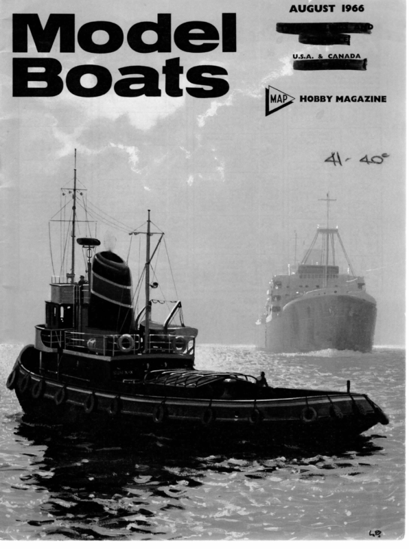
AUGUST 1966 U.S.A. & CANADA HOBBY MAGAZINE
MODEL BOATS 10-RATER CHAMPIONSHIP A promised report on the 10-rater championship, held at Easter at Fleetwood, has yet to materialise, but one of the yachtsmen present took these pictures which give some idea of the fleet and the conditions, which were generally cold, wet and windy. Photo 1 shows Francis, a handsome Lewis boat, 2 the wellknown Triplané, a former winner. Picture 3 is of her sailing Warlord, 4 Chris Dicks’ 60 in WL moderate displacement Midnight, a very successful model. Photo 5 shows the winner, 322 Warlord, a 60 in. WL lightweight bulb-keeler with a rotating wing mast; designed for glass-fibre construction, she has no actual deck, the cross-section forming almost an oval. 6 is Dennis Lippett with Thief, another famous champion, 7 is another view of the winner, and 8 an experimental entry, Walter Jones’ unusual twin bulb-keeler Logic. Winning boat entered by R. Blick (Guildford) and sailed by him and Roger Stollery; notes on it will be appearing later.
MODEL BOATS SIMPLE ARITHMETIC CAN CONTRIBUTE TO THE SUCCESS OF YOUR MODEL: SOME SIMPLE SUMS DESCRIBED. BY A. J. R. BELFORD, B.Sc. STABILITY FORMULAE FOR BOATS ‘THE serious model boat builder is usually able to calculate many of the factors pertaining to the design of model craft, but the stability is frequently judged by experience or trial. It may sometimes happen for example, say, in the case of a model steam vessel, that the builder is in some doubts as to whether he should set his boiler high to obtain a good firing space and risk instability, or vice versa. It is in cases such as this that a formula for calculating the stability of a floating body is of value. The following data apply of course to models and to full sized craft. First let us consider the concept of the ‘‘Metacentre’’. A body floating on the surface of a liquid is under two forces. There is the force W due to its weight, acting downwards through the centre of gravity of the body, and there is the upthrust U, exactly equal to this, acting upwards through the centre of gravity of the displaced liquid. If these forces are not in line, the resultant couple will either tend to right the body if G is lower down than M, as shown in figure 1, or else tend to capsize it further if G is above M. The point M, viz the point in which the upthrust U meets the axis of symmetry of the body, is known as the ‘““Metacentre’. In general it varies according to the inclination of the body, but as the axis of symmetry MG is brought to the vertical, M tends to a limiting position. If then we can calculate the position of M it is only necessary to provide that the centre of gravity of the boat lies below M and the boat will be stable. The further below M the centre of gravity is brought, the more stable the boat will become, i.e. it will be able to right itself through a steeper angle. Now consider figure 2, representing the cross section of a vessel. The plane in which the boat meets the surface of the water is termed the “Plane of flotation’’. This is just the plan section at the waterline. Let M be the Metacentre Let Let Let about C be the centre of gravity of displaced water V be the volume of displaced water in cu. ins. I be the moment of inertia of the plane of flotation the axis of the boat in inches+. Then the Meta- centric Height in inches = MC = v It will be observed that this is a rational formula i.e. if we take 1 in cm‘ units and V in cubic cms. MC = ¥ will be in centimetres, and so forth. Notwithstanding the great simplicity of the equation, considerable calculation may be required in evaluating I and V. The task, however, may be simplified by making use of approximations, but to be on the safe side, the error in approximating I should be low and in approximating V should be high. The moment of inertia of a plane about a line is defined as the sum of all the (elements of area multiplied by the square of the distance from the line). We may therefore use this method directly as shown in figure 3. If we divide the plane into strips parallel to the axis XX, multiply the area of any strip by the (length y)?, and add them all up, we get an approximate moment of inertia about XX. If the plane of flotation is divided up into a few thick strips, the work is simplified but is not so accurate as if we divide up the figure into many narrow strips. Mathematically the value of 1xx is the sum of an infinite number of strips, each infinitesimally wide, and multiplied by its respective y . Alternatively the plane of flotation may be divided into rectangles, trapeziums etc. provided the axis of symmetry XX passes through the centre of each component. The moment of inertia of the figure is then the sum of those of each component. Figure 4 gives properties of a few simple sections. The volume of displaced water may readily be found by calculating the weight of the vessel and determining the volume of water to equal this. If a predetermined waterline has been calculated, the volume may be roughly assessed by dividing the submerged part of the hull into slices through the section lines and treating each section as a short prism. To obtain the centroid of the displaced water is more difficult. If the main cross section of the submerged portion is rectangular (as in the example below) or trapezoidal, triangular or elliptical, the approximate centre of gravity may be found from the data in figure 4. Since however the metacentric height MC is generally large compared with the discrepancy in the position of C, the slight errors caused by approximating this centroid are not serious. In order to amplify the method of calculation a concrete example is given:- Suppose we are contemplating building a canoe of dimensions as shown in figure 5, and of estimated weight 100 Ibs. Two persons each weighing 140 Ibs. are to sit in the canoe amidships. It is required to find the metacentre. Take the foot as the unit of length. 342
AUGUST . MOMENT OF Fig.4 INERTIA POSITION OF Ixx | CENTROID OG 1966 wed 2D : RECTANGLE 3 F +58 arenes a a TRIANGLE | El eee eis ae 6 b.d. bd 3 2 bd 2 — d bd ofa) 98 | O-d 3 . b (042d) b (Dtd 4b TT bd 3 (Ord) TRAPEZIUM -SEMI-ELLIPSE| OR | : d SEMI CIRCLE 380 The plan area, (dividing into triangles and rectangle) 4 + ge oy 4 28 Hae =4(7 x 104) x 34=114 cu. in. = 0.25 feet ii) Prism 7” wide, 34” deep, 2’ 3” long with 24” radii =(7 xX 13+2 x 244-47 X 242) x 27=725 cu. in. The centroid of a rectangular section, see figure 6, is iii) Quarter Sphere 34 rad. 36 cu. in. ier pe UCU equal to half the depth. =EX$ Xo KSg* “. OC = 40.25) = 0.125 feet The waterline plane may be divided into one rectangle and two triangles. The moments of inertia of these 48 2 6x (2.5)3 4 3.75 (2.5)3 ect => 48 3.75 =(2.5)) (+5o + = 48 bd3 Ixx= 4 3 *. Metacentric height =MC= yea —— =1.675 feet . Gg o> 9 in. i= os = a 170 in. = iii) Ellipse *. MO=1.675 + .125=1.8 feet=214 inches : = 104×7 = ii) Rectangle 15.6 aun + oe + 0.078) r ial 10.1 => 875 cu. in. I=Second Moment of Area of Surface Plane This is likewise divided into three sections i) Triangle (data from figure 4) are 3.5 x (2.5)3 4 7 > V=Displaced Volume. This is divided into three sections i) Triangular Prism 7” base, 104” long, 34” deep. = 4.4 ” 15 + 4.7 = 24.1 sq. feet 24.1 317 Figure 7 shows a model cargo vessel of somewhat simple construction. This was built round a Stuart Turner single cylinder double acting engine and the boiler was made from a fire extinguisher case. Using inches as the unit of length. is ee 6:1 cubic feet ….-: 655 so ew ols (1) 61 64 = Example for model work V= Displaced volume due to 100 + 280 = 380 lbs. water is 62.5 lb. per cubic foot. .’. The submerged depth = / T bd T tees has mwxX344 ; Thus the canoe will remain stable provided the centre of gravity of the vessel and passengers is not more than 214 in. above the bottom. For seated passengers this is about level with their necks, but obviously the canoe would be instable if both passengers stood up. It is easily seen from these calculations that the stability would be considerably increased by either lightening the vessel, say by removing one passenger, as this would decrease V and leave I unchanged and hence MC would be increased, or alternatively by increasing the beam to, say, 3 feet, which would have the effect of increasing I while ‘V remained unaltered. 343 64 64 7 in.4 ~—- 852 in. I 852 So MC= vp .975 inches. The centroid of the displaced volume is obviously slightly above the centroid of the central section assumed rectangular, i.e. point C is at least 1gin. from the bottom. Hence the metacentric height = 1.625 +-.975 =2.600in. This is shown on the drawing. From an examination of the cross section it is apparent that the stability of this model will be critical. To remain stable the centroid of the ship must lie below the point C. The heavy plank along the bottom contributes to this, as would the hollowing


