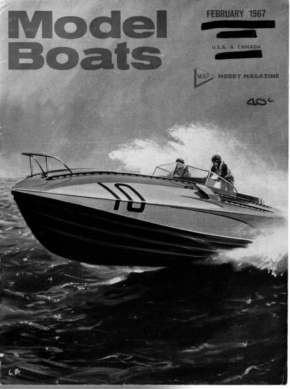
- WARLORD Winner of the 1966 10-rater Championship, this was one of the most unusual boats launched during the year. How and why are described by ROGER STOLLERY
- Readers Write…
- STARLET BOATING FOR BEGINNERS CONTINUES WITH MORE ON BUILDING & FITTING OUT THIS 34” R/C OR FREE-SAILING YACHT

WME Lies
FEBRUARY 1967 WARLORD Winner of the 1966 10-rater Championship, this was one of the most unusual boats launched during the year. How and why are described by ROGER STOLLERY order to be able to hang some lead in the keel, But the amount of ballast necessary depends on where the lead is placed. If the centre of gravity of the keel is close under the hull, more lead will be needed than one where the lead is placed low down well away from the hull. If ballast is reduced by this means the total dis- BEFORE starting any design iit is necessary to give the basic dimensions considerable thought because these, more than anything else, will determine the boat’s performance. A study of the historical trend of increasing length, which is very prominent in the 10 rater class, indicates that a choice of a 60 in. waterline length jis in the natural line of progress. Chris Dicks, with his design Midnight, has already shown that 1,000 sq. in. is sufficient sail area to drive this length successfully in all conditions. If one accepts the penalty of the reduced sail area in light weather one must take a careful look at how resistances can be reduced to allow this to be successful. Both beam and displacement are controlling factors of wave making and frictional resistances, and one would like to reduce both these dimensions to the minimum. This can probably be taken to the ultimate only in the case of the catamaran where extremely fast hulls are achieved because the hulls themselves are designed with no reference to stability. However, where sail carrying power must be provided by the hull itself one is faced with the problem of combining this with a hull of low resistance. To windward when heeled the driving forces are largely dependent on the stability. The more stable the boat is the more sail it can carry, and thus, the more driving force it can develop. But one must not forget that speed is a balance of driving and resisting forces and that the reduction of resistance is just as important in deciding the speed. Normally, to obtain greater stability the beam and displacement are increased. However, by doing this the resistance goes up by a similar proportion and one is left with a similar ratio of driving force to resistance and therefore similar speed. How ‘then, can the stability be provided without incurring increased resistances? Obviously one must have some displacement in placement is reduced and with it wetted area and wave making resistance. A fast boat results because the ratio of driving force to resistance has been increased owing to the sail carrying power remaining constant and the resistances being reduced. Also, in light weather a smaller sail area can be accepted because the wetted area of the hull has been lowered. This line of thought, which has proved successful in Marbleheads, applied to the design of Warlord results in the choice of a 28 Ib. displacement, a beam of 11} in. and a bulb keel with a draught of 134 in. The main advantages of lowering the centre of gravity of the boat have been outlined already, but there may also be hidden advantages in the actual form of the simple plate and bulb as opposed to a conventional shape. At first glance one might think that one would lose out because the lateral area of the plate is far less than the lateral area of a conventional profile, But in practice it is found that boats using this simple form of bulb keel are more close winded than normal. It may be because there is always a flow of water down the keel and where normally this is allowed to flow freely off the end of the keel, with a bulb it is blocked by the bulb itself and this creates considerable Jateral resistance. A bulb keel does not necessarily have a higher wetted area, in fact because of the above observa- tions it can easily operate efficiently with far less. To compare its wetted area with a conventional keel profile it is sufficient to add one half of the profile area of the bulb to the profile of the keel as a whole. After the basic dimensions have been considered the next problem is shape and how to treat the overhangs . Having only designed boats without them I was at a loss to know what to do with these luxury items. A careful study was made of photographs of boats with overhangs, and this confirms experience of sail- ing in Dragons, that a long forward overhang is nearly always out of water. It contributes nothing to any increased sailing length and is therefore inessentiai. Further, a long bow overhang implies a filling out of the section at the forward waterline ending, a blunt-
MODEL BOATS ing of the waterlines at the bow and an action to windward that bashes rather than slices. Experience of Marblehead design shows clearly that it is the shape of the underwater sections that determines the nose diving action of a hull and not the reserve buoyancy above water. Therefore, Warlord is designed with the minimum of boat above water at the bow and a short overhang implied by the fine waterlines. The stern overhang, on the other hand, is drawn out as long as balance allows because it always gets wet and not only provides extra sailing length but acts as a damper to pitching. The resulting shape, while balanced, shows a dissimilarity between the ends, which makes its action to windward smooth and easy in the short steep waves encountered on lakes with concrete edges. Today, when many boats are produced from one design, it is natural to think of glass fibre construction as being the method of achieving this with the least effort and in the least time. If the pattern is prepared under the supervision of the designer, WARLORD R. STOLLERY — — =< 7. 6 _——— BEAM 11-6" LWL BEAM 1125" DRAUGHT 13-5" DISPLACEMENT 28\b. LOA 74" LWL 60" MAX. SAIL AREA 1000in* SECTION SPACING 6° BUTTOCK&.WATERLINE SPACING 1” SECTIONSS BULB FULL SIZE \W ‘ PALL 5 |CB28b. 4 2 ia | | : = ian —— | i AAN /\\ —— oo Wie SERVICE MAKERST, HEMELPLANS MODEL HERTS HEMPSTEAD, 13—38 BRIDGE 5 20 Ib. lead svn ze oe —— 2a 4 JW Saal eee ae 60 6 _ oe a
FEBRUARY 1967 accuracy is ensured and many moulds or hulls can be distributed from this one pattern, as desired. This leads to the speeding up and easing of the building process. Warlord is designed with this in mind, and a glance at the sections will reveal that there is no gunwale on the hull and that the shape of the sections follows an unbroken curve right round the hull. This is the result of dissatisfaction with the present incongru ity of plastic hulls fitted with traditional wooden decks. Why have a gunwale? It only creates eddies in the water on the lee side and eddies in the wind on the windward side. There are many advantages in such sections apart from pure performance. If the two halves of the hull are joined at the line of maximum beam (as marked on the profile) there is no tumblehome on either half and therefore the laying up of the glass, as well as the withdrawal of the hull from the mould, is eased, This type of section allows a better stress distribu tion within the hull itself with a consequent reductio n of hull weight. A simplified keel and mast structure can aE a (Tee ei ee ee 9 hud 16:4"all suits n sail plan quarter full size ot also be achieved if these sections are used in conjunction with a plate and bulb keel. If the plate is brought right up to the deck the bending moment s on the bottom skin of the hull are avoided and the plate can be used to house the mast both at the step and at deck level. If the rigging is taken through the deck and back to the plate, then all the main stress between rig and keel are self-contained almost without reference to the hull (see diagram 1). This again leads to a reduced hull weight, The buildin g of such a boat is simplified and becomes purely the assembly of a few major components: deck, hull, skeg, plate and bulb, plus, of course, rig and fittings. Although the drawing shows 20 Ib, lead this should be reduced if necessary to keep the total displacement at 28 Ibs. The rig suggested shows a 14 in. wide mast and a heavy roach on the mainsail. The roach on 10 raters ie is unlimited and one is only restricted by the limita- _ top suit mainsails, one with as large a roach as possible and the other with a roach that is more suitable tion of sail materials. It is suggested that one has two ‘, {an ae 5 rr.) eo = ee for moderate wind strengths, The 14 in. wide mast must rotate and the boom must be set at an angle to it to allow the top of the mast and sail to blend into a fair curve (see diagram 2). (continued on page 86) ee line of leach line of view of mainsail fromabove . diagram 2 IAA
MODEL BOATS Readers Write A neat little wallet of double-ended chrome-vanadium spanners in 0-8 B.A. sizes is awarded to the writer of each letter published. These columns are open to all with an interesting viewpoint to express, a point to be made, or a helpful experience to describe etc.; the Editor is not necessarily in agreement with opinions given. VANE v. R/C Dear Sir, Having been described as conserva- tive by Mr. Pemberthy in the November issue, | am provoked to words in defence of model yachting with vane steering, which | think are due. It is a pity in this respect that your editorial policy is to encourage radio-controlled yachting, since interest in R.C. can only be at the expense of vane yachting. Model yachting has come a long way from its origins of racing replicas of full size yachts, and as far as the designing, handing and skills involved are concerned, it has become a sport in its own right. | find it difficult but possible to convince my non-yachting friends of this. Now the R.C. model yachtsman arrives and tells us that we can make our sailing ‘‘iust like the real thing”. It seems to me that he has somewhat missed the point, and as also the expense of R.C. yachting is of the order of that of dinghy sailing, some further justification is needed. In my view the problems, as opposed to the skill, of model yacht control were solved by about 1955. A vane gear, once set on a course, leaves littleto be desired; watch the yachts at a big meeting if you doubt this. Indeed, for beating to weather, or keeping a spinnaker pulling it is probably better than any helmsman at all, let alone one on the shore 100 yards away with a potentiometer. The advantages of R.C. seem then to be in manoeuvring. One is that yachts could be raced on open water, or the sea. This is a very real advantage indeed, as fickle inland wind is the number one bugbear of model yachting, and this advantage could yet make me an R.C. yachtsman; but the fact remains that R.C. yachts use the same ponds, lamentably few, as vane yachts do. Another big possibility is the triangular course. Now in full size sailing on the open sea, a triangular course around buoys is the natural outcome, since it would be both inconvenient and boring to sail until the next land were encountered; but no-one could maintain that sailing the 300 yards or so of even one of our longest ponds is either inconvenient or boring, indeed a yacht running really fast down it with a spinnaker is one of the finest sights to be had. Vane yachts do not often reach, but this is not a very interesting point of sailing. On open water, of course, it would be another story. To judge by the rumours of one-design R.C. yachts, the R.C. conversions of out-classed vane yachts and the number of non-class R.C. yachts one sees cruising around, it seems to me that its adherents subconsciously like radio controlled model yachting not for any of the involved technical reasons mentioned above, which do not stand examination, but simply because they like radio control, and model yachting is an in- triguing and not too hectic a way of applying it. This is a fair enough reason, but | have yet to hear it admitted. To the novice attracted by R.C. yachting, | would advise to bear the above in mind. If you like wiring, and poking in black boxes, with some yachting thrown in, then by all means go ahead; if you want tactics and control of a helm, then take up dinghy sailing; but if you like the shapes of yachts and keen competition then take up vane yachting, and do not tolerate being dubbed as conservative, or as a poor relation. A vane steered yacht is a delightful machine for extracting speed from the wind, the fact that it does so completely of its own accord is one of its best features. Cambridge. R. A. Phipps. FOOD BOXES NOT ESSENTIAL Dear Sir, | should like to reply to the letter of Mr. M. E. Robinson of Cumberland in December, 1966 issue. He writes, ‘The reason | don't compete in competitions is that my boatis not suitable for the typical regatta course’, and carries on, that the boats that are suitable are nothing more than floating food containers, fast and nippy but not boats. | presume that Mr. Robinson is talking about radio comps. | myself cannot comment on the radio side as my pocket is not deep enough to buy this modern radio equipment, but in the straight running comps. the club which | belong to, the Watford Marine Model Club, run nothing else but prototype boats. Nearly all these are steam driven and we compete against large cabin cruisers powered by lawn mower engines. We may not stand as good a chance as these boats built for straight running, but quite often surprises do happen. Between us we win quite a fair number of comps. Also, at the Grand Regatta in 1965, Mr. McLelland of the West London Club, won the steering comp. with his beautiful steam yacht Elizabeth. This | thought was quite a feat as | believe there were round about 100 entries. What I suggest Mr. Robinson, take your boat along and enter the comps. Even if you have not got much of a chance of winning, at least the spectators will appreciate a good looking model, and who knows, it might encourage the builders of the fast, nippy food containers to think again and build a nice looking boat for their next model. Besides, entering comps. is a great deal of fun, and we ourselves have a 68 grand time with the chaps from the othe’ clubs. They are a jolly fine crowd and if you could possibly attend the Grand Regatta at Victoria Park, London in 1967 you will see what | mean. Hoping to have been alittle help. Bushey. L, Disney. FLOATING VOTER Dear Sir, | feel | must write in answer to Mr. Thompson's blue pencil letter. Let me say at once, it’s been said many times before, ‘You can please some people, some of the time .. .’’. It would be true to state that there is a certain amount devoted to the ‘‘mice and flea” brigade. When | conjure up a model maker in boats, | visualise him making his way to the pond or lake after he has completed his model. | see little point in making a model boat to grace the sideboard or mantlepiece. One other factor—there are too many ‘“‘kit bashers”. This is an easy way out. A young lad brought a fine model of a 30 in. launch round to show me. Beaming, he remarked, ‘‘This is what /'ve made”. Now, every part was bought, even to a friend painting it for him. I'd like to see more scratch builders’ articles. Then, and only then, can they consider themselves what | call a true model boat enthusiast. In conclusion, | welcome the change from ‘'M.M." to ‘‘M.B."". There are some issues which to me are not quite so interesting as the previous, but then there's the next issue to look forward to. Could we not have ‘‘Readers Write’ on one page, also a caption under each photo, most annoying to figure out which is which! pswich, Suffolk. D.F. Millon UP WITH SAIL Dear Sir, | have just read in Model Boats the comments of readers to Mr. Thompson's letter, and | feel that | have something to say. Only one of the readers’ comments had anything to do with sai/—all the others were power men. Where are all the yachtsmen? In my opinion Model Boats means boats or ships of all types, shapes and sizes, but | do feel it should have a type of dividing line, for use of a better word. It should be 50% power boats and ships, and 50% sai/, both for the racing yachtsman, pleasure, miniature and period sailing ships. | would like to see some articles on deck fittings, sails, types of materials, vane gears, which are the motor of a yacht, and also an article which I have never seen in Model Boats, advice and tips on how to sail in competitions and races—the little things that mean so much and can cost you a race. Let's have some of these articles instead of the hull designs all the time. It’s no good having good hull designs if there is nothing to drive them or they are driven incorrectly. | do hope that this letter is published in Model Boats, because | would like to know what other readers think, and this is an excellent way to find out what subjects your regular readers require. Birkenhead, Cheshire. D. Williams
Hn MODEL BOATS STARLET BOATING FOR BEGINNERS CONTINUES WITH MORE ON BUILDING & FITTING OUT THIS 34” R/C OR FREE-SAILING YACHT HE area of deck remaining inside the cabin, and the interior of the cabin sides, should be painted or varnished thoroughly, In rough weather a small amount of water will inevitably find its way in; it may be only a drop or two, but the wood must be thoroughly waterproofed. 3 Screw the mast step in place, using two $ or j in. no. 2 brass countersunk screws, and saw away the upper section of the backbone aft of B3, back to the rear of the hatch. This makes access to the interior easier—even if radio will never be fitted, it is often necessary to sponge out water, and the top of the backbone has done its job once the deck ‘is on. The fixed part of the cabin top extends from SI to S3, but laps only half on to $3, A slot } in. wide must be cut to correspond with the mast step, i.e. 13 in. long fore and aft, and it is recommended that the top be cut with a spare } in. or so overhang each side so that it can be glued on, strapped with rubber bands, and the mast introduced through the slot, engaged with the mast step, and sighted for truth. Obviously if the slot is out of alignment the mast can never be rigged vertical except by trimming away one side of the slot. A slip of xs in, ply, $ in. wide by, initially, some 2 in. long, with a % in. hole centred 14 in. from one end, will ultimately be slipped on the mast and tacked temporarily to the cabin top with sticking plaster while initial trials are carried out. When the correct mast position for the individual boat has been found, the surplus will be cut from this slip and the remainder glued over the slot. Parts S3A and S4 now need to be lightly pinned in place and a further piece of ye in, ply fitted to form the remainder of the top. This is glued only to S3A and S4, so that when dry the pins can be withdrawn (through the windows in our case) and the movable part of the cabin top lifted off. A strip of 4 in. sq. or even 4 in. x 4 in. along each side, to locate inside the cabin sides, is desirable, A smal] nick must be taken out of the after edge to clear the eye which passes the main sheet, which is a permanent fitting screwed into S82. Paint or varnish the top and underside of both sections of the cabin top, and the hull woodwork is virtually completed. If no cabin is fitted, make a hatchway in the deck big enough to pass a hand through and line the edge under the deck with reinforcement timber. A small coaming, say + in, x + in. laid flat, will prevent a great deal of seepage, and a cover should be made to extend over the coaming. The best material for the plug is cork glued to the underside of the cover (two thicknesses of cork table mat etc.) a tight fit in the hatch opening. For a boat of this ‘type, a painted deck is probably best—in full-size the deck would most likely be fabric covered and painted or just possibly varnished mahogany ply. It is necessary to decide at the outset 74 .. shar yyy pt MIMULLULMUL ULM LLL LUE Y Wp just what colour scheme will be used, since a vainished or a stained and varnished deck will need to be almost completed before any paint is used on the hull sides. Paint creeping over the gunwale on to a bare ply deck will leave ineradicable traces which will mar a varnish finish; the only cure would be a 4 in, wide band of paint round the deck-edge or even a rs in. thick x 4 in, wide “cover board” added. The same applies to the cabin (or “coachhouse’’) which should be stained and/or varnished before any paint is applied to the deck if this type of finish is deired. Some builders will, no doubt, wish to plank the deck and it would do no harm to carry this out with thin veneer. Alternatively, two coats (at least) of varnish or deck colour can be applied and flatted off thoroughly with very fine wet or dry carborundum paper. Make a pencil mark on the surface and check that it can be rubbed out; if not apply another coat and rub down again. Mark out a waterway 4-3 in. wide round the deck edge, in pencil, and a king plank 4-3 in. wide down the centre. Draw in a surround } in. from the cabin, all round, and also inside the dummy cockpit. If a simple hatch is fitted, draw the surround { in. outside the line of the hatch top. Now draw in 4} in. wide planks, either running straight fore and aft, from the king-plank outwards, or parallel with the deck-edge, from the waterway inward. Straight planks should be “nibbed” or “joggled’’ into the waterway, curved planks into the king-plank, as sketched. In either case, where the planks meet a thwartship timber (e.g. front of cabin) a simple butt joint is all that appears. Having drawn the pattern in lightly with pencil, either go over it with a sharp, hard black pencil, or with a ruling pen loaded with indian ink. In the latter case, slips can be removed when dry by lightly scraping with a pointed piece of razor blade. Varnish over, one or two coats, to complete. If water or spirit stain is used on any part, make it rather diluted; it is easier to get a smooth and even colour with several thin coats than one at full strength. Remember that varnishing will darken the
FEBRUARY 1967 Left is the jib rack, shown about twice size. Curtain rail origin is obvious. Mast step is similar, but with slots instead of holes in the centre strip. Below, mast heel. Screw has yet to be filed off. Note nick for sideways engagement on mast step. colour down—it is better to end up with too light a colour than too dark. Since past experience indicates that some builders are keen to colour their models in the same way as the original, perhaps we should mention that our scheme is pale blue hull with a dark blue stripe at the waterline, pale blue cabin sides, white deck and white cabin top. Our sails are white, but coloured sails are often cheaper when professionally made. Let us return now to fittings. Last month we covered the mast step, jib rack and mast tongue, and mentioned the mast bands. We also promised details of a wood mast in case difficulty should be experienced in obtaining } in. tube; since the fittings for the mast must be made to suit, tt would be as well to cover this point first. The ideal material is undoubtedly Sitka spruce, but this may be hard to find. Any other of the spruce types would be acceptable for a model of this size, and it is possible to laminate two pieces together if Left, the gooseneck, made as described from an old light = switch. Original pivot hole can be seen. Mast band clamps U-bracket in place tightly. Photo below shows stage of making mast bands from % in. wide strip, bent in vice round dowel as described. Next step is to cut off surplus, drill, and file tags to shape. Drawing below shows (diagrammatically) form of nibbing if planked deck is to be represented. 75
MODEL BOATS Cabin before adding fixed top. Note mast step screwed into place and backbone section removed aft of bulkhead. White fore and aft line in floor area is top of fin in position between backbone doublers. smaller sections of the right length can be found. We require initially a 4 ft, length } in. square. Alternatives are Oregon pine of other hardish long-grained softwoods; often a length of pre-war picture rail from a demolition job will provide an ideal piece. Only in extremes use dowel, and then make sure it is clean and straight-grained beech and not any of the present-day hardwoods such as ramin, If dowel must be used, + in. diameter is adequate. The aim is to produce a mast } in. dia. at the maixmum, this point occurring one third of the length (16 in.) from the heel, or Jower end. The afterside will be left straight, the bottom one inch will be 2 in. dia., and the top will taper down to a bare #s in, four inches from its tip. All tapers will be straight. It will be seen that starting from a square trip is easier, since the shape can be marked on the faces and the timber planed to correct tapers etc., before being rounded, The cross-section will be approximately circular at any point. The heel of the mast can be further reduced to slip tightly into a 4 in. stub of } in. o.d. brass tube, and mast tongue fitted as described previously. Mast bands must be made to fit the mast at the appropriate points, and the mast sanded and varnished thoroughly before the bands are finally fitted, For best practice, the appropriate eyes etc. should be silver soldered in place and the interior of the band filed to make sure no eye shank protrudes; the bands are fixed by block of brass in the bracket shown on the drawing; this bolt allows the block to swing sideways. A similar bracket on the boom, turned at right-angles, with a horizontal bolt, allows the boom to pivot up and down. The boom bracket can, in fact, be two plates fastened to the sides of the boom, either by bolting or binding, or more elaborately, two extensions to a brass “box” fitted over the end of the boom. If the block is provided with two “fingers”, the end of the boom can be fitted between them and a bolt passed through. Such a block can be filed from a piece of brass or made by silver soldering a U-piece round a stub of tube, the arms of the U projecting parallel to each other far enough to engage the boom. Our own block was simply the toggle of an old brass electric light switch; the type to look for has a porcelain base with a screw-on brass cover. The toggle (the bit you move with your finger) is mounted on a pivot inside and has two fingers extending from it which engage an insulation strip which throws the switch mechanism, We removed the toggle from its pivot, removed the insulation strip, sawed off the bit that sticks out through the hole in the switch cover, and drilled a hole at 90 deg. to the original pivot hole. It took no more than a couple of minutes and provided a perfect piece for the gooseneck, Try electricians for one of these old switches—there are plenty still to be found in old properties now being re-wired. One other job remains on the mast, if a kicking strap is not to be fitted (we will touch on this next time) and that is the provision of a jackstay, This is a thin wire (stainless steel, e.g, control-line wire) run up the after side of the mast, to which will be clamping as for the metal mast. Incidentally, some yachtsmen silver solder a small piece of brass to the outside of one lug of a mast band, and drill and tap holes through this to receive screws through the other. This is a refinement—the nutted bolt we are hooked the sail. The wire should run from the gooseneck to a point 40 in. higher, and is kept tight to the mast by means of 10 B.A. bolts (or tiny roundhead woodscrews for a wood mast), the slots of the bolts or screws being arranged vertically, the wire slipped into them, and secured either by pinching the slots closed with pliers or putting on a dab of soft solder, The bottom of the wire can be looped through a tiny hole in the gooseneck bracket and the top using is really adequate. Possibly the most awkward fitting to make is the gooseneck. This is simply a universal joint which connects the main boom to the mast and allows the boom to swing from side to side as well as to pivot upwards. The pivoting allows the set of the sail to be controlled, where such adjustment is included, or alternatively cushions the yacht against gusts by spilling air from the sail. A simple gooseneck can be made by bolting a made off to a screw or bolt. 76
Mob BOATS FIGHTING FLEETS (continued from page 70) WARLORD (continued from page 61) There used to be no restriction on the size of the mast in the 10 rater class but since the appearance and success of Warlord in the National Championships at Fleetwood, the free area gained by the mast has been limited to a 14 in. width. Warlord was originally designed with a wing mast similar in construction to a model aircraft wing which measured 6 in, at the base and 3 in. wide at the top. The mast revolved and the boom angled relative to it as described above for the 14 in. mast. Naturally, the extra area gained by this mast produced a good performance on the light weather day of the Championship. However, on the other two days, when it was. necessary to change down, there was no advantage gained by any extra sail area because one couldn’t hold it up. What was surprising was that it was in these conditions that Warlord was the most impressive. Not only did it point higher but it footed faster than any other boat, and this is reflected in the fact that Warlord did not lose any points to windward throughout the Championship. Although performance is a balance of many factors there was one thing which helped Warlord to victory more than anything else and that was its fine bow. Unlike many of its rivals it did not bounce and pitch, but cleanly sliced through the short chop at the leeward end in a most graceful and efficient manner. One of the things to emerge from this champion- ship was the supremacy of the 60 in, waterline. Only two boats saile¢ on this length and they finished Ist and 2nd. There is a vast amount of work to be done on the 10 rater rig and particularly on the wing mast. Although the 14 in. mast shown is not measured as sail area it would be worth experimenting with wing masts which are measured as sail area. If these are developed fully waterline lengths of 60 in. will cer- tainly be far too short. ““CYUNGA"’ steering boat. Northern Champion 1964, 1965. Miles i 3.5 c.c. Diesel. Six channel Radio new Superhet Rx. Excellent top competition boat ready for next season. Cost £80, £40 o.n.o. **Model 10 c.c. Glow B. Min-X, 8 Channel Tx with 2 matched 4 Channel Rx’s. (1 Relayless) with 2 Bonners. All as new. Offers. B. Grime, 110 Worcester Road, Blackpool, Lancs. ODEL Sails in Terylene. Nylon spinnakers. Price list of racing suits from Nylet Ltd., Park Road, Fordingbridge. Hampshire. B.G. XCITING new illustrated catalogue no. 17. Government and manu- facturers surplus electronic equipment. Also a large selection -* new miniature components and semiconductors. Ready end of January. Send for your copy. Now 3/- post free. Arthur Sallis TiC: Radio Control Ltd., 93 North Road, Brighton. ANTED. Model Maker (Model Boats) 1956, 1958, 1959 and 1960. £3 per volume paid. Millington, 19 Furham Field, Hatch End. Pinner, Middlesex. Phone HAT 4534. sides. A tiny length of 15 amp fuse wire can be inserted to act as a spacer betwen the two sides and should be placed vertically at the hook end and at the bend. Incidentally this lead foil can be used for many features on these models. It is by far the best material for solid rails and bulwarks, can be used for decks and platforms, and is an excellent material trom which to make funnels and barbettes, In those rare cases where unpainted steel decks are encountered it can be used without paint for a most realistic effect. The vents around the funnels on both classes should be made up from layers of black construction paper interspersed with card or thin wood that has previously been painted hull colour. The black paper should be recessed slightly for the best effect, Note on the “Z” Class that only the pulling boats near the second funnel are equipped with goose neck davits. The motor boats on each side of the bridge are handled by light derricks. The braces on the light tripod mast should be made up from contact cement “strings” applied before the funnel is installed, The structure in front of the bridge has a raised deck in the centre which comes to the level of the solid rails. records. R.C.M.E. 1966 in mint condition will pay full price Mr. J. B. Nimmo, 9 Sternhall Lane, Peckham, S.E.15. ILES being drilled before attempting to cut out the crane for interesting lists to 17 T/€ HREE (3) three-foot Model Boats Tether for sale. Holds all speed March, April, May, Makers’’. Box No. 310. used in toothpaste tubes. The crane should be made up in two pieces, the holes in the upper member HIP PHOTOGRAPHS. Fine quality post-card size ship pictures. 12s. month. March, plan, It is not necessary to cut this recess as it can be adequately represented by matt black paint provided this is applied before the forecastle deck is placed in position. The large crane is somewhat fiddly and is best made from heavy foil such as is per dozen. Write, with 4d. stamp, Mannering, River House, River, Dover. Box replies to be sent care of Advertising Department, 13-35 Bridge Street, Hemel Hempstead, Herts, England. Copy received after first post on December 29, 1966, will be held over until the next om unless cancelled in writing before 24th of following February. structure. This is indicated by a broken line on the Case and Aerial, 45/-; Working perfect. suitable Model Boat. B. Rayman, 40 Avondale Crescent, Enfield, Middlesex. PRESS DATE for March issue, 1967, January 27, 1967. Private Minimum 18 words 6/- and 4d. per extra word. Trade Minimum 18 words 12/- and 8d. per extra word. Box Numbers to count as six words when costing. ANTED. a common practice on German destroyers. There are a few points that the modeller should note on these ships. The torpedo tubes on the “K” Class rotate into a recess in the side of the super- ADIO Control Ivy Carrier Wave Receiver 50/-; Transmitter Minus CLASSIFIED ADVERTISEMENTS ‘‘Model Boats’’, also hull colour but could also have been painted white, B U.S.A. Ken Franke, 948 Valley Road, Clifton, New Jersey. A.M OVERNMENT Surplus Electrical and Radio Equipment. Our new catalogue, No. 16, ready now, 2s. 6d., post free; cost refunded on purchase of goods over £2 Arthur Sallis, Radio Control Ltd.. 93 TC North Road. Brighton. AINT TRANSFERS. Numbers, Letters, } in. to 54 in. various colours. Samples and list. Transletters Ltd., 219B High Street. Orpington. A.F: ODEL Racing Yacht Sails. All classes—stamped addressed envelope for prices. Arthur Levison, 80 Weydon Hill Road, Farnham. Surrey. LIG LANS! Schooner Yacht ‘Creole’. 5 sheets, authentic, model sized lovely 3 masted vessel. Scale suits proprietary fittings. 76 in. x 58 in. x 13 in. Working or showcase 75/- set CWO or S.A.E. for B. details. Rhodes, 22 Barnes View, Sunderland. ADIO Control Supplies, largest stockists of R/C equipment, engines and accessories in the country. H.P., Part Exchange (Transistor equipment only). Call, write or phone, ISL 0473. Radio Control Supplies. 581 London Road, Isleworth, Middlesex and at 52a London Tye Road, Leicester. Aeronautical Press Ltd., Worcester, for the Proprietors, Theto Model (Worcester) Limited, Hylton Road,23/37 Made and printed in Great Britain by Impress Tudor Street, London, E.C.4, whom all trade enquiries should Ltd., 13/35 Bridge Street, Hemel Hempstead, Herts, Published by the Argus Press Post. Magazine Canadian by for transmission be addressed. Registered at the G.P.O.


