- Description oBILL PERRY DISCUSSES THE MODEL DESCRIBED BY WALLY JONES AS “THE FASTEST SAILING MODELIN EXISTENCE” —THE CATAMARAN ARAWA
- STARLET MORE ABOUT FITTING OUT THIS 34in. RADIO OR FREE-SAILING YACHT IN OUR SERIES ON BOATING FOR BEGINNERSf contents

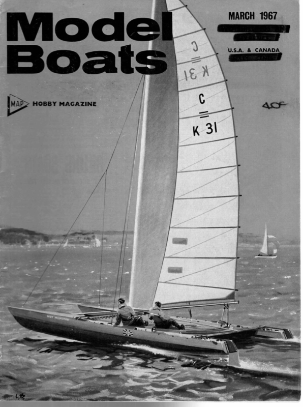
MARCH 1967 sae U.S.A. & CANADA
MODES BOATS BILL PERRY DISCUSSES THE MODEL DESCRIBED BY WALLY JONES AS “THE FASTEST SAILING MODELIN EXISTENCE” —THE CATAMARAN ARAWA I FIRST became interested in catamarans about 15 years ago after reading about the exploits of the Polynesian navigators of the 12th century who seem to have been able to sail all over the Pacific Ocean in their double hull canoes. Their exploits inspired me to build a model and find out for myself how it would sail. My first model was quite small, about 15 in. long, with This one was larger, 40 in. long, maximum beam 16 in., hulls 2 in. beam with a pronounced sheer, 4 in. freeboar d in the bows tapering down to 2 in. at the stern. I fitted a movable centre-plate in order to be able to adjust easily the C.L.R. Cat. 2 was a considerable improvement on the first. The pronounced sheer completely cured the dig in tendency of the lee hull. It would sail very fast with the windward hull completely clear of the water. This seems narrow canoe shaped hulls and a central plate with a small piece of lead for ballast. I reasoned, as most people seem to do, that a catamaran is sure to capsize and in order to prevent this it must have a ballast keel. I sailed this on Birkenhead lake and it seemed to me to sail quite well. The lee hull had a definite tendency to dig in which I cured by fitting hydrofoils on the bows. One day I had the courage to remove the lead weight and what a difference it made! It went like the proverbial bomb. This demonstrated to me that a ballast keel is detri- to me to be the ideal way for a catamaran to sail, sailing on the lee hull which must be able to support the total weight of the boat plus the weight of the wind on the sails. In order to prevent a capsize, it became clear to me that the wind pressure on the sails must be balanced mental to a catamaran. I didn’t much care for the hydro- foils—they didn’t seem very seamanlike to me—so I set about building another model. Various Arawa points. views show Picture \ of top, es the previous. 40 in. model. Note mast-head jib in heading photo drawing. 98 and ;
MARCH by the weight of the windward hull and any increase in the wind pressure must be able to be transferred to forward motion of the boat before the point of no return is reached. This demands the least possible resistance to the acceleration of the boat; no unnecessary weight, long slim hulls with fine entry, and the least possible size of fin are therefore required. I have often heard it said that a catamaran is unable to beat to windward. This, I must say, is quite untrue. Arawa is quite capable of beating up Birkenhead lake in three tacks. There are, however, two points I would like to make quite clear. (i) It is not always advisable to try to point as high as possible. With the sails sheeted hard in there is often too great a risk of a capsize if caught a bit off the wind by a sudden gust. (ii) The faster a boat moves into the wind, the finer the angle of the apparent wind becomes and in order to keep the boat from coming into wind, it must be sailed at a greater angle off the wind. This gives the appearance of sailing off the wind and with a catamaran’s high speed this is much more apparent. As Cat. 2 was not fitted with any means of steering and I was becoming convinced that model catamarans were capable of being sailed under competitive conditions and might stand a chance of being popular, I decided to build point. I reasoned that I might as well go the whole hog and build one that might well be the ultimate practical size. This turned out to be LOA 80 in. and max. beam 29 in., which is about the largest that will fit comfortably on acar roof rack. The hulls have very much the same lines as Cat. 2, pronounced sheer and slim, 2} in. beam, and as it is essential for both hulls to be identical in every way (except, of course, in the case of asymmetrical hulls when one must be a “mirror image” of the other) I Arawa, which would be a practical way of testing the SAIL PLAN * h 6 : \ ——— SS==TMW —— (Continued on page 101) HULLS SPLAYED 7° SsssEESSS 1967 : = gre”. LEE HULL UPRIGHT WHEN HEELED 4 PLYWOOD ¥4 PLYWOOD 3 Ss “ “q PLYWOOD | 2a/” | am y” 5%o”% 2″ ALL SECTIONS Ye CIRCLE AFT ‘ARAWA’ 15″” 4″ CENTRE PLATE MADE FROM Va” SHEET WITH SECTIONS THUS
MODEL BOATS STARLET MORE ABOUT FITTING OUT THIS 34in. RADIO OR FREE-SAILING YACHT IN OUR SERIES ON BOATING FOR BEGINNERS DEPENDING on the wind strength, etc., best performance for a yacht can only be assured if the “flow” of the sails is adjustable, the flow being effectively the degree of curvature and the amount of belly in the sail. The standard present-day racing model has “loose-footed” sails, i.e. the foot (bottom edge) of the sail is not laced or hooked to its boom, but secured only at the tack (fore bottom corner) and the clew (aft bottom corner); the boom simply provides an attachment point for the clew. To avoid pressure losses, the sail needs to be as snug to the mast as possible, so the tack is fixed. The clew, however, can be moved by a simple adjustment called the clew outhaul (perhaps we should apologise at this point for not spotting the error “clean outhaul” in one place on the Christmas plan!). Obviously, if the outhaul is set up as hard as possible, the foot of the sail is stretched taut and will adopt the mini- VM Yi belly, but the depth of this belly arrangement sketched covers these points completely, is and is a common method of satisfying the conditions. For Starlet (and indeed for many larger models) only the main boom carries this fitting, the ability of the jib boom to lift and the jib to spill a little air being far less important. The main member is an ordinary stainless bicycle spoke; as shown at A the spoke is cut to length and the cut end threaded (approx. 8-10 B.A., depending on the spoke used). A washer can be soldered, or a nut and washer run down to the end of the thread, to fit below the gooseneck bracket, a nut and washer on top securing the gooseneck, C is a mast band bearing a thin lug bent affected by the general stretching forces applied to the sail. One of these forces is supplied by the clew outhaul, and the other by a device used to control the amount of vertical lift of the free end of the boom. This is the kicking strap. If the end of the boom is pulled down as low as possible, the leach (aft edge) of the sail is drawn taut; since the luff (fore edge) is hooked to the jackstay and pulled up hard by the uphaul, and the foot is taut, the whole sail will be drawn as flat as possible, the condition used for strong winds. By easing the clew outhaul and the kicking strap slightly, more flow is allowed in the sail, maximum flow usually being used in the lightest of winds. To allow the boom to swing freely, the kicking strap must pivot on the same vertical line as 1, Up efforts must be made to reduce binding or other interference with free movement of the boom. The mum curvature in the wind. The cut of the sail gives it a natural l out at right angles (note that the mast band will not bend to a perfect circle because of this drilled to provide a bearing for the spoke, being exactly the same distance from the those in the gooseneck bracket. The spoke is bent up to angle shown ordinary nipple will screw on. A piece of the boom, and, since there is quite a pull on the “strap”, lug) and the hole mast as and an stainless steel wire (control line etc.) is secured to the nipple by sawing a narrow slot each side of the mushroom head, slipping the wire in one slot, wrapping round the body twice, and passing the other end through the other slot and twisting off on the other end. If the ends of the wire are tucked through the wraps before twisting (easy to do when you try it!) no soldering is required for a secure fixing. The free end of the wire will eventually be made off to an eye on the boom, so that screwing the nipple tightens everything up. Naturally the wire twists, but not to a serious extent. An alternative, shown at B, is to use the threaded end of the spoke as the top (gooseneck) end, using the threaded portions sawn from two nipples as nuts, and to bend the other end into an eye. To this eye 122
MARCH is fitted (either direct or by means of a wire jump ring or link) a bottle screw (also known as a turnbuckle) which is a standard fitting, being a body with left and right-hand threads and appropriately threaded and eyed inserts. When the eyes are secured against rotation, turning the body lengthens or shortens the distance between the eyes. The free eye is attached to the boom with a short length of stainless wire. Quite considerable force can be put on this fitting in a blow, and cord will stretch, hence the use of metal. The top of the mast, if a tubular one has been used, is a length of dowel etc. It takes no particular load and a ready-tapered top can be found in the form of a cheap round paint-brush handle. The a requires to be stepped to plug into the mast Readers’ 1967 Survey Many readers will remember that in the past we have invited their views on what they like (or would like) to see in Model Maker & Model Boats. With the recent correspondence on contents in mind, now seems an appropriate time to ask all readers to express their opinions. A survey form is included in the back of this issue; it can be cut out without affecting the rest of the pages, and it has been made as simple as possible to fill in. Postage is paid in Great Britain; may we ask you to have your say? tube. To complete the mast the hounds fitting must be attached, and it is best to through-bolt this and attach a tag to each end of the bolt to receive the shrouds. There is quite a downpull on this fitting and the bolt prevents any chance of slipping; it also avoids for these the only problem is the sail winch. We are therefore jumping a bit for their benefit. Any four-channel radio of reasonable weight can be fitted, and the rudder servo will be conventional. A self-neutralising servo is likely to be most people’s choice, but some may like to try a progressive one, which has the advantage of enabling two or three degrees of helm to be applied, which is sometimes useful. Unfortunately it is also hard to know when the rudder is completely neutral, so that what is gained on one leg can easily be lost on another. The sail winch, on the other hand, is not a con- soldering. Soft solder is unreliable in yacht fittings, especially where salt water is involved, and silver soldering is something which many modellers have never tackled, so that in this model soldering has been avoided as far as possible. The remaining job on the mast is simply a fine hole drilled through fore and aft about 4 in. below the top of the metal tube, This hole needs to be polished as far as possible—even putting the point ventional fitting and has usually had to of a school compass in and rotating it will remove is that the cord uphaul for the mainsail passes through it and ‘is drawn tight, so that a possibility of fraying occurs. Sketches etc. will appear when we reach the rigging stage, but briefly the cord is secured to the sail headboard, passed through the mast, and finished in a loop and bowsie. A hook is fitted to the loop and engages in the top hole of the plate in the hounds fitting, tightening the bowsie thus draws the mainsail luff taut. Before model, a are fitted a stand. any further work is carried out on the stand is essential. Once the ballast bulbs it becomes less easy to work on it without Probably the easiest is to make the base from a 15—16 in. length of 1 x 6 (or wider) timber, and to screw to each end a } in. ply plate, the top of which is cut to fit the V of the hull. Two strips of 1 in. sq. should be screwed to the base to provide sideways location for the keel bulb, and the area between them should be padded with foam plastic. Foam rubber tends to stick to a boat put on the stand wet and allowed to dry. The edges of the ply be made. It is often said that it must have a worm drive in it somewhere, so that the sails cannot drive the winch, With 1,500 sq. ins. of sail on a Q class boat this may be so—forces of 10lbs. have been recorded —but with about one third of this area and probably one ninth of the maximum force, the chances of driving back through a 50:1 spur reduction are small. As it happens, there is on the market a device which requires only a drum to be fitted to make a perfect winch; this is the Mini-Richard unit imported by Ripmax. This uses a Marx Luder Milliperm motor any burrs. The reason for taking care with this hole and is a unit offering adjustable gear ratios of 3:1 down to 60:1 in six steps. It is 2} ins. long by 1 in. diameter and weighs only 14 ounces; it has ample power for our purposes and is easy to use. With a reed receiver it is simply wired to the appropriate » reeds, but with an all-transistor set it needs a T.A.S.A. switcher which we will deal with in due course, It is recommended that the drum fitted has a small core diameter. Fuller details will be given for the not-soexpert, but the eager types will have enough to carry on with from this mention. which cradle the hull bottom should also be padded, with plastic sheet, or split rubber tube, or thick felt or baize, which can of course also be used for the bottom padding. Sail Winch Quite a lot of people are building this model, and some are ahead of these notes. One or two are anxious to get radio installed and get sailing, and The Mini-Richard, shown here only a shade smaller than actual size, is a natural for the sail] winch and removes the biggest problem. 123 eae


