- Fittings for Model Yachts Part Two By C. W. Sykes
- Readers Write…

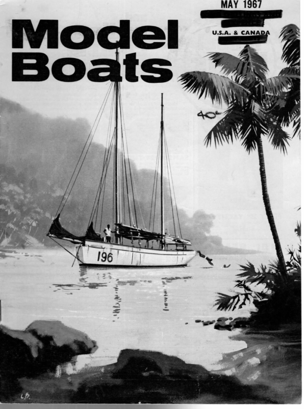
MAY 196/ © U.S.A. & CANAD
MAY 1967 Fittings for Model Yachts Part Two By C. W. Sykes Be next step is to make or buy a suitable vane gear and in the Bournville Club, of which I am a member, preference is for a moving carriage-type vane gear rather than the breakback type. Details of the one I have made are as follows and it is clearly shown on the photograph. It is of fairly robust construction and in this respect is possibly superior to the breakback type and is also more positive when beating in light airs. In some instances, depending on the position of the rudder, it is possible to mount the vane gear directly on to the rudder post and this I try to do for it tends to make a more compact installation. In the case of Golden Archer, however, this is not possible and a link has to be provided between the gear and the rudder operating mechanism, but nevertheless my aim is to make the vane gear as compact and as self-contained as possible. With this type of gear the first thing to be decided is the gear ratio between the vane and the rudder and on a Marblehead a reduction of two to one is accepted. The gears, having 16 and 32 teeth at 4 in. centres, are then mounted in the moving carriage which can be cut from 16 gauge brass or stainless steel plate. First, draw out or scribe on the plate the shape you want the top and bottom of the carriage to take, centre punch the outline slightly, and then commence cutting out with a hacksaw. If you choose stainless steel a good supply of saw blades will be needed. If you have difficulty in cutting straight, I should recommend mounting the metal in the vice, using copper vice grips, and placing it in such a way that the line to be cut is just showing and parallel to the top of the vice jaws. Then cut along in a horizontal plane using the vice jaws as a guide. When sawing is completed a file should be used to smooth over all edges, splitting the marking out centre punches down their centres. The gears are mounted on stainless steel spindles, is in. and 3 in. dia., each end pivoting or turning in brass bushes silver soldered to the carriage. One tries to drill the holes in the carriage as accurately as possible to make sure the gears mesh correctly and if the gears are designed to work at 4 in. centres the correct clearance is allowed for when they are cut, so that it is only necessary for the gears to mate without any undue pressure. If you have no machine tools at your disposal to obtain the correct centres for your gears, you will have to rely on accurate marking off and drilling, and possibly slight slotting of holes may be needed to get the gears to mesh correctly. In my case I use a lathe to do this work and I bolt both the top and bottom of the carriage on to a back plate which, in turn, is clamped on a vertical milling attachment on the lathe table or cross slide. The carriage is set in a horizontal plane by using a scribing block at the correct centre height and a centre drill is then placed in the three jaw chuck and the lathe saddle moved forward until drilling commences in the correct place. The centre drill is then removed and the correct size hole produced. To produce the second hole the lathe cross slide is moved in or out exactly -500 in., this being checked by using the dial attached to the cross slide handle. If, when the carriage is assembled, things tend to be a little tight, metal polish is used to lap everything in and it must be remembered that for any vane gear to work correctly all moving parts must be nice and free but with backlash kept down to a minimum. All bushes must be accurately drilled and to obtain a correct size hole in the absence of expensive reamers it is my practice to drill a hole smaller in diameter than the one desired and then put through the correct size drill. Invariably, if the correct size drill had been used straight away the hole would come out oversize unless the drill was perfectly ground. When opening out brass, however, care must be taken and it does, in fact, pay to grind off the drill cutting edge or otherwise the drill tends to dig in. The top and bottom halves of the carriage are held apart by three } in. dia. pieces of rod which can be silversoldered top and bottom or riveted over. In the case of this vane gear, however, the top is removable as the gears are enclosed with a perspex shroud cut out from a solid block. This helps to keep out dirt, sand, etc. The carriage is supported on an extension of one of the bottom bushes and pivots in a housing which in turn is screwed to the deck. On this housing two stop screws are provided which control the amount of move- ment of the carriage when the vane is unlocked and set for beating. A suitable lock has also to be incorporated to enable the carriage to be locked in place and in this case it takes the form of a small bolt. Another feature to include is a spring loaded device which helps to snap the vane over when going about on the beat and hold it in place. As can be seen from the photograph the front end of 197
MODEL BOATS 46″ THICK BRASS WOOD SCREW 4g” DIA. BRASS ROD > STUCK IN WITH PINTLE TURNED FROM 46″ DIA. S.S. ~ RiIVETED ON UNDERSIDE ARALDITE 8 BA CSK. SCREWS cutting tool mounted on its side in the tool post. After one half has been marked off the protractor ‘is moved round through 180° and the process repeated. The lines which have been formed are then filled in with red paint and small number transfers stuck in place so that positions can be readily repeated. On the zero line of the dial I usually cut this a little the vane gear is attached via pull over lines to the main horse so that as the main sail moves over it takes the vane gear with it. Attached to the rear of the vane are two rubber or spring loaded guy lines which are pulled tight when the boat is required to On top of the vane gear a suitable dial marked off in divisions is fitted and also another scale is desirable to check the angle of the moving carriage when beating. The dial on the vane gear is made from perspex vs in. thick and anything up to 2 in. dia. This size gives something to get hold of when fingers are cold and numb! On the dial I scribe lines at 10° intervals with a shorter line in between giving a mark every 5°. To do this I mount the dial and secure it by two 8 B.A. Screws On a centre spigot, which in turn is held set at in the three jaw chuck. Behind the dial I mount a protractor and by using a scribing block correct centre height the chuck is moved round deeper and ‘paint this one black for ease of rapid identification. With this type of gear, when one is on a reach or run it is customary to point the black line in the direction you want the boat to go and depending on where the wind is coming from set the vane accordingly. Under these conditions the vane usually is in the locked position. When beating, however, the vane is set fore and aft and the lock is undone and the only thing to worry about is whether you have set your beating angles correctly, which can vary a little depending on wind strengths. With a gear of this type there is a two to one reduction through the gearing and as the carriage rotates about its centre when beating this gives a ratio of three to one, or a movement of 1° on the vane carriage, when altering the beating angle, equals the vane feather. 3° on O the 5° at a time and a line cut into the perspex with a screw — 16″ DIA. 3- 3/32″ DIA HOLES ON 198
MAY FOOT ASSEMBLY STUCK IN PLACE WITH ARALDITE ° @ RIVETED IN PLAC k 1967 4g RIVET 7 32 THICK BRAS. 4 BENT FROM %e”x 46 BRASS AND SILVER 7 BA SCREWS SOLDERED TO BASE The rudder post is pivoted on pintles at both ends and a sketch illustrates how the bottom one is supported, for if you simply rely on wood screws, especially if the skeg is plywood, these tend to fall out after they have been screwed in and out a few times. The sketches show alternative systems which can be used (a) when the skeg is perpendicular and (b) when the skeg is at an angle. When the boat is complete and sails fitted it will have to be measured and rated and if you intend to sail seriously numbers will have to be provided on the sails. The numbers have to be a certain size as laid down in the sailing (Continued on The top photographs on these pages show a similar vane gear fitted to the author’s 36R model, a modified Duck. The enclosure of the gears in a Perspex block is apparent. Photo bottom left and heading on page 197 show the gear without the Perspex casing, fitted to the Vega Marblehead design Greentop, Other fittings, including a novel radial also visible. Drawing below is full-size for the gear used on Archer design. horse, are the Golden page 196) ) O P | O O C) ie on me ee CONNECTING ROD TO TILLER ARM ATTACHED HERE GEARS ENCLOSED . DIAL SA6 DIA. Bi: a IN PERSPEX a] LONG °/30 aati rT it | | \ —— – 1] 6 BA : ‘ uJ Ke an it SPRING TENSIONING DEVICE — a ay =
MODEL BOATS Readers Write… A neat little wallet of double-ended chrome vanadium spanners in 0-8 B.A. sizes is awarded to the writer of each letter published. These columns are open to all with an interesting viewpoint to express, a point to be made, or a helpful experience to describe etc.; the Editor is mot necessarily in agreement with opinions given. CANADIAN SUBS Dear Sir, There seems to be a little controversy regarding radio controlled submarines, following the article in the December 1966 Model Maker & Model Boats. Judging by the letters received by the Metro Marine club, the reaction is either genuine interest or sheer disbelief. However, as a recent immigrant to Canada | am glad to be able to report my own findings. My son and | attended the recent boat show in Toronto, where there was a large tank supplied by the exhibition authorities for the use of the club (Earls Court take note), and they laid on daily a boat show of their own, but, of course, only electric boats were eligible. Nevertheless this little show was quite impressive. All types of radio controlled models were on show ranging froma little 14 in. plastic kit model of the Utah, built and controlled by a junior member, up to a 50 in. (approx.) model of H.M.S. Campbell complete with a beautifully made scale 5 in. gun that actually works, made on the revolver principle, firing .22 blank shot. This model and the submarines formed the high spot of the club show. The gun is controlled for training and elevating, and the two models were used to portray a sub-destroyer battle, both models manoeuvring with the destroyer firing a round at the sub whenever it appeared on the surface. | can assure you these submarine models really control superbly under radio-control. | have spoken to Dr. Rogers and examined the boats. There is no genie involved, just standard superhet equipment on the 27 m/c band. Two of his models were on show, one using an aerial embedded in the hull itself, the other using the periscope with a second cover the same shape over it making it completely waterproof. For diving only the forward hydrovane is used. The boat is built just buoyant, and forward motion with the vane down forces the sub below the surface where it remains in perfect control. Should the model hit any obstruction under water, it will surface as soon as forward motion ceases. Although | have not seen it in action, the Doctor also has a later mode! of Skipjack, the U.S. atomic sub, which he controls with the stern hydrovanes. Another model on show which caused great amusement with the children around the pool was of the Canadian patrol boat Re/ay, a very nicely finished job, complete with fire monitors on the foredeck which were also trainable and also worked, powered by an ex-windscreen washer motor, the operator giving the children a squirt on passing around the lake. The show was also supported by two members of the ‘‘Buffalo”’ club from the U.S.A., one with a Sub chaser, again beautifully detailed even down to tiny too!s on the deck workbench, and the other with a plastic kit model of a tug about a foot long and radio controlled. | regret | did not take along a camera on this trip, but | will obtain any photos I can later and send them. | would like to add a word of reproach to British suppliers of model equipment. | have had several complaints from modellers here about the cool, to say the least, reception these people get from you—enquiries ignored completely, orders taking far too long to answer. Modelling is growing fast here and all equipment is scarce. Here is a market just waiting for you, so wake up ! Canadian dollars are just as much in demand as U.S. dollars. Watercooled engines are practically non-existent. Many people are interested in the Gannet for instance. Super-regen radio is out because of walkie-talkies which are only too plentiful. | would like to quote an instance of bad service, e.g., a Canadian wrote twice in six months after Superhet equipment from a well known English manufacturer and to date has received no reply whatever, so he just bought American equipment which costs between $119 to $615 American. Ontario. R. A. Ramage. NO STRANGLERS, PLEASE Dear Sir, | feel | must take up Mr. Roberts on a couple of points in his letter (March Model Boats). The chine boat is designed for simple building and while it may be a little unsightly and not as seaworthy as some, almost anyone can build it. The bulb keel is also designed for simplicity, but also efficiency, and 100 per cent efficient it is too. It looks no more child’s play than a conventional fin keel. On aracing yacht one wants to have more stability, i.e. Bulb. There should be no doubt by now that if a bulb keel is applied to a hull of light or moderate displacement a very fast yacht emerges. Mr. Roberts also mentions Warlord. | had the pleasure of mating the skipper of this yacht at Fleetwood on the first day. It did have a revolving mast which gave it about 280 square inches unmeasured, but it was still superior when on a third suit of sails. No, it wasn’t the extra inches Mr. Roberts says were pinched that gave Warlord the championship. | believe that Mr. Stollery has succeeded where others have failed in designing a light 10 that will go in all conditions. Perhaps | had better point out that it has a bulb keel ! As for 10s getting as large as A boats, ot course they will get as long and longer because a 10 rater can be developed to a greater extent than an A and length means speed. To be competitive now one has to “‘join ’em”’, and that means a 60 W.L. No, don’t strangle development please Mr. Roberts—too many are trying already. Chiddingford, Surrey. F.R. Shepherd. 212 WINGED Dear Sir My feelings regarding letters written for publication are that contributors should confine themselves to constructive subjects or mind their own business. However, | cannot help expressing a personal objection to a couple of ill informed and downright untrue remarks made by Mr. Roberts in his retrogressive, rambling letter to which you saw fit to give useful space in February M.B. | know not where Mr. Roberts obtained his information because Warlord did not pinch anything from anybody. lf he could force himself to read the design article again it may become clear that due to the prevailing conditions we were unable to make use of the free wing area, allowed by the rules, for the greater part of the championships. In fact, for some of the time the wing was an embarrassment down wind and lost us many points. Had it not been for the tremendous windward ability of the hull configuration even luck would not have won the championships. Warlord, built and owned by myself, was designed by Roger Stollery to produce a hull which would be faster than any other boat under the 10 rater rules, as they then stood. When I was 14 years, | rigged a 4 ft. yacht with half the wing of a damaged model sailplane. It was a logical progression to use this idea (not my own) some 20 years later when renewing my interest in a class which made provision for such a rig. Loopholes in rules are the responsibility of those who make them. It is no credit to Mr. Roberts’ era of modellers that this rule has gone unchanged for so long. Had the rig used on Warlord been illegal the boat would not have been given a_-rating certificate or would have been disqualified in her first major event. As it was the rule had to be changed, and quite rightly, to eliminate the possibility of an undesirable trend. Having been shown the danger the M.Y.A. Council moved with commendable swiftness, Incidentally, | have it from a reliable source that in the dim and distant past Mr. Steinberger fitted a wing to a 10 rater but considered it not worth continuing with. The conventional rig now fitted has done little except prove the exceptionally advanced hull design and more than makes up for my lack of experience in model racirg, Has Mr. Roberts actually seen Warlord in action? | doubt it. If not he will have a better opportunity this season. There will be at least three racing, and Warlord will again carry a wing mast designed to suit the modified rule. Poor Mr. Roberts, enquiries are tumbling in for glass fibre hulls from modellers who share my view that Warlord is a beautiful creation and has a grace of movement which has been absent from model racing heretofore. Little else in his letter is worth replying to, except that should Mr. Roberts see my nine-year-old son gallivanting after a pre-war designed orange box to the 36 in. class rule (once raced in his heyday) he may accept that whoever said ‘‘Beauty


