- Chinook An unusual 52in. w.!. hard chine yacht for R/C sailing, described by its designer and builder C. S. Gould
- Improve Your Performance Hints on yacht tuning by M. J. Harris

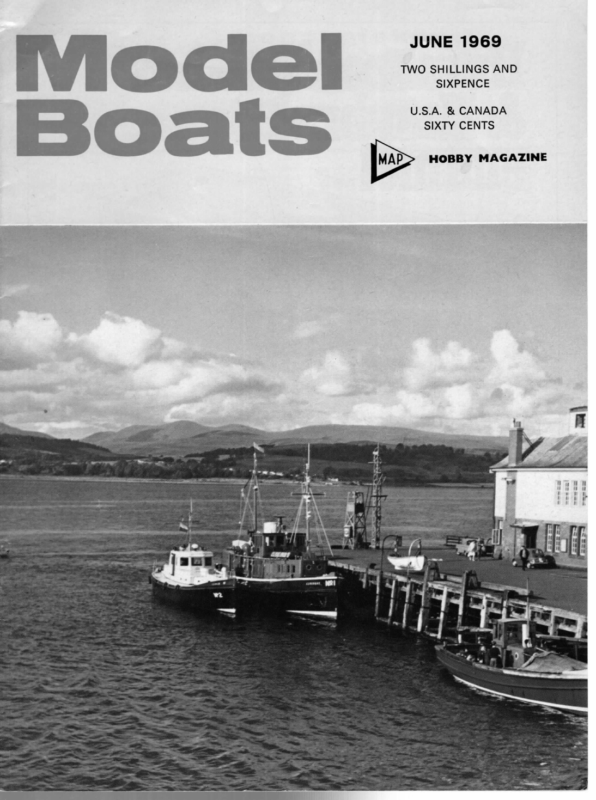
> ec: JUNE 1969 TWO SHILLINGS AND SIXPENCE U.S.A. & CANADA ea SIXTY CENTS [ua HOBBY MAGAZINE A
HT MODEL BOATS Chinook An unusual 52in. w.!. hard chine yacht for R/C sailing, described by its designer and builder C. S. Gould A FTER dabbling with a variety of models, from a the conversion of an old 10R X.P.D.N.C. and a China Boy M class to a }M, Marktoo, a tug, and the scaled Stormvogel, Blue Glass, several of which have been discussed in these pages, I decided that the next project would be a yacht designed and built from scratch. Do designers usually build? If so, some for simplicity of construction and ease of transport; it would have to be capable of offering serious A yacht must, I feel, have a _ pleasant basic appearance; I also believe that the chine boat has not of Witty’s Hornet, which is the boat to beat at the must be kept very busy! been fully developed in the model world. Some readers may remember the fantastic performance of Daddy Long Legs in taking the 10R Championship at Brighton a year or two back. A chine boat of moderate size was decided upon, competition to other models in the club, sailing under R/C, as our water is not suitable for free sailing. Since sailing became popular in the club, the fleet has increased to four Stormvogels, a good Daniels 36R design in glass-fibre, two old tens, and two Marbleheads, one of which is a superb g.r.p. version moment. With this in mind, a boat of 52in. l.w.l. was decided on, with a fair amount of freeboard, as our water gets a bit lumpy in a blow. A fine entry, 9in. beam, and a fine delivery produces something like a drawn- out China Boy, which has always proved clean through the water. The average angle of the bow V is 96 deg., while aft of the fin it is 110 deg.; the 12in. deep fin gives a draught of 1Sin. Various calculations by Simpson’s Rule, etc., indicated a displacement of around 201b. So much for the preliminary paperwork. The moulds were set up on the building board and we were in business. Chines are jin. sq. pine, inwales 5/16 x 4in. pine, and the keel backbone laminated from two lengths of } x 4in. pine. Skin is 1/16in. ply, fin keel 3in. mahogany marine ply, deck beams {in. sq. obeche and deck Imm. ply. The bow and stern profile were given a reasonable angle and the l|.o.a. came out at 56in. Bow and stern blocks are laminated and hollowed to about 4in. thick from a wood called oruba, which is quite hard and excellent for shaping. The top of the fin is braced by four triangular webs to distribuic the loads over the huli to the chines. A plastic pcn, reinforced with g.r.p., forms the rudder tube. The complete hull, with deck, varnish, and paint came out at 3lb. 150z. After priming with thinned varnish, the deck was given seven coats of white Humbrol, rubbed down between, until a smooth matt finish was obtained. It was then lined out with a drawing pen. The king-plank is brown, as are hatches and gunwale cover boards. A power blue hull with a wide red waterline and tin. wide yellow coving line produced an attractive appearance. Influence especially ‘China Boy’ stern. canoe of is evident in general (top layout Fin/lead unusual. shape and is photo)
JUNE 1969 Bath trials were quite interesting, the canoe body and fin without ballast were so light as to be completely unstable, floating, like a square baulk of timber, on the diagonal axis. The ballast required to bring the hull to the desired w.]. proved to be 14Ib. After the bath trials, which, by the way, needed the overflow to be plugged in order to obtain the depth of water, the deck was given the usual three coats of being in the neutral position on the slide and rack, the rudder max. limited at about 35 degrees. When set off she picked up speed fairly well until clearing the lee of the shore line when she really sliced away at a good angle and sailed very straight. the fine entry and delivery plus low wave-making shape belying her actual speed. As expected the beam rat’o of six and a half to one gave an easy heel to about ten to when pressed harder in the rising varnisn rubbed down, the lead bulbs cast and epoxy fifteen degrees; ‘M,’ but with a full batten at the top to carry a very think a narrower but even deeper fin could be used, as Mr. Witty said in one of his articles, ‘How deep can one go?’ Is the extra wetted surface of any significance? On this trials day the height of the waves was between four and six inches, even higzer bonded in position. Deck fittings are of stainless steel, and the mast slide is of laminations of sixteenth ply. Again it is intended to use the ‘M’ mast and rig, except that I now have a special suit of sails. The jib is modelled on my ten and the main is similar to an large roach. The necessary seats have been fitted into the hull for the radio box and the rudder servo, which now uses four channels. The ornamental! hatch covers are 1 m.m. ply with imitation glass and wind she noticeably stiffened up. This makes one near the lee shore where reflected waves were generated as on most competition ponds. Suppose one compared the wetted surface of the boat in still stainless wire guards. These are usually frowned upon by the racing man, but are less than half the weight oi some I have seen at regattas. Finally, I think many readers would be interested to read how some of the real experts build and paint their racing and championship boats, but they never seem to write in Model Boats. One almost gets the impression that apart from your coverage of regattas they belong to secret societies; we get lots of designs from well known designers but only a rare article on fittings and rigging, usually a real stumbling block for beginners. This is the sequence of painting which was adopted for Chinook: (1) Varnish hull inside and out, two coats inside, one coat outside, also one coat under side of deck. (2) Fit deck and rub down with 280, dry, then varnish. (3) Rub down varnish on deck and apply white coats until upon rubbing down, wet, a good matt surface appears. (4) Mark M.L. and draw in deck planks in Indian ink. (5) Mark out king plank in ink and paint up to lines. (6) Rub down and paint gun’I strips. (7) Rub down and paint hull (being a chine hull I tried a new method doing one half at a time), rubbing down with 280 and 320 paper used wet. (8) When a satisfactory surface appears fix gun’ strips. (9) Fit deck fittings and make hatch covers. (10 When hull has dried out, do bath trials, mask and paint waterline and coving line and add boat’s name in Letraset. The hull is then given a burnish with a car cleaner and a coat of polish, which, I believe, is controversial as I have read that a waxed hull had a greater resistance in tank tests than one without, is this why water stays in globules on a polished car? Sailing trials At last, after two weeks, a snow and_ ice-free Sunday with a light breeze suitable for tuning. It did not last, and no sooner was the boat unloaded at the pool when the wind moved to become a moderate easterly, with a drop in temperature promptly inducing shivers. The normal ‘M’ top suit was rigged and, soon, all was ready for the launch. Apart from the wind being chilly, an east wind is known for its steady blow in this area, coming straight off the North Sea unobstructed. The sails were trimmed for a beat up the pool and a reach back, the mast and jib water and sailing in a lop, my guess is that you would find almost a thirty per cent. increase. The only fault that revealed itself in this trial was a distinct slowness to tack, being inclined to hold in irons longer than Blue Glass or my old ten. This may be due to the deep vee form, and inherent straight sailing qualities coupled to the fact that the thin section fin is more difficult to stall; there was no hanging when the reverse procedure was applied, i.c., gybing. Probably a fin of laminar flow section would be the answer. However, after this first run the jib was gradually brought back one hole at a time until the roach was just touching the mast, but only a slight improvement was noticed. I am not a believer in the superiority of the ‘Slot Effect’ as was evidently disproved in the Redwing trials where the jib is carried far enough forward not to overlap, also the ‘C’ class catamarans with their Una rig on a wing Continued on page 261 249
rt MODELL BOATS plumbob Left, Fig. 1 i Right, Fig. 2 | AL | Jig for checking Fin and Skeg “ Improve Your Performance wire jib stay | with turnbuckle | wire | ogustment backstay eewire jumper Hints on yacht tuning \ stay wit) _ turnbuckle \ by M. J. Harris wire main shroud 2 with turnbuckle PHS article is for the benefit of beginners who have been sailing for a season or so and wish to do a little experience. privilege I better now personally of sailing with they have Mr. C. have the W. gained pleasure \ | some Sykes and cord tail and so have the advantage of sailing boats which are efficiently rigged and well prepared for racing. This article will not guarantee that you will win, but if the advice given is followed then performance should | fw/ improve. in that it is stipulated that it must be absolutely straight in a fore and aft direction. This is not so. The five main points to have special attention paid to them are: (1) Hull, fin and skeg; (2) Mast and sails; The mast should be set up so that the sail sits on it with no creases or wrinkles in it. However, if the mast needs to be bent a lot to get the sails to set (3) Rigging; (4) Fittings; (5) Steering gear. Hull Make sure that the hull is fair and has no unnatural hollows or bumps in it. It is worth while making a rough jig to check whether fin and skeg are in line and not warped or twisted (see Fig. 1). The hull finish should be smooth, not necessarily with a shine, and have no deep scratches or grooves. It is worth the time and effort to secure a good finish as a rough hull only creates resistance to the water. Check that the boat floats on its designed water line. If it does not do so then adjust the lead keel until this fault is corrected. Boats are designed to sail most efficiently on their designed water line. If it is down either by the head or by the stern then the resulting discrepancy will affect your boat’s performance. Mast and Sails The sails are the driving force of a boat. If they are not set correctly then power is lost. They should sit on the mast with no creases, wrinkles or cracks in the finish of the sail. If the clews are stretched and puckered remove the reinforcing corners and replace them so that the sail is once more flat or if the damage is too far gone then replace the whole sail. It is a waste of time sailing with sails that resemble sheets of corrugated iron. The main cause of distortion of sails is generally the overtightening of the luff when racing and then afterwards forgetting to ease them. Even the best quality Terylene will protest when subjected to maltreatment. The mast, which supports the sails, has had a cult almost akin to religion attached to it in recent years, 252 then the sail needs recutting. Remember it is better (o have a slightly undersized, well shaped, efficient sail than a sail which is on size but has creases running from corner to corner and does noi drive well at all. Rigging The rigging of a boat offers much to the inventive mind, the only trouble with this being that one frequently sees boats at races in which the mast looks like a spaghetti tree with wire in every direction. This creates windage. The golden rule in rigging a boat is keep the gauge of wire as fine as possible and keep rigging itself down to a minimum. Remember that minimum rigging equals minimum windage. If the mast is adequate section then large amounts of rigging are not required. My own preference is for: 1 pair Main standing shrouds with bottle screws; 1 pair running back stays with bottle screws; 1 main wire back stay with cord and bowsie on the tail; 1 cord fore stay (Fig. 2). I can see no reason for augmenting this if the rigging is correctly sited on the boat. Booms The simple rigging as of the possible. booms The should running be rigging kept as should preferably be made of best quality cord. I have seen boats that have used cord of the bright orange Ulstron type and chalk line. Both of these stretch and are totally unsuitable for accurate trimming. The main boom should have an adequate kicking strap with screw thread or bottle screw adjustment. A cord kicking strap is just not accurate enough. With respect to the jib it seems ludicrous that we devote so much time and trouble in controlling the
JUNE 1969 angle of the main boom but when it comes to the jib we tend to rely on a hook and a piece of string. My own personal preference for the radial jib boom is based on its accuracy of setting. There is no need to build a radial jib of such classic proportions as those produced by C. W. Sykes. The type used by Roger Stollery, Fred Shepherd, etc., is extremely simple to make and extremely accurate in use. If, however, you do not have the inclination or do not wish to fit a radial jib arrangement on your boat I would urge that you use a wire jib stay with bottle screw adjustment which will enable a certain amount of trimming to be done as regards flow, etc. All boom fittings should be kept as light as possible but without any loss of strength. Model Boats magazine produces a rigging plan with fittings for simplicity in their Plans Handbook range. Fittings As regards deck fittings the best thing to do after a season’s racing with your boat is to take it home and take a good hard look at it. Decide what fittings you lack to improve your boat so that it may be sailed more efficiently. Decide which fittings. are doing nothing at all or which you did noi use in the preceding season and remove them. Are there any pieces that could be lightened or modified to work better? Would a particular item work more efficiently if it were re-sited? If so, do so. Steering Gears For the purposes of this article I shall split this section into two parts, section A being vanes of the ‘break back’ type, i.e., those of the Fisher, Lassel, Richey, Corbey and Jones type, section B being those of the ‘moving carriage’ type, i.e., those of the Cunningham, Wilcox, Stollery and Sykes type. Section A The main point about these type of vanes is that the pintles must be absolutely upright and vertical to the waterline, not the sheer. If this is not so then the vane will not be balanced when the boat heels. The guying equipment should work and you _ should practise, in all ranges of winds, guying off the bank. For good competitive windward work it is essential ENTERPRISE (continued from page 250) ships was repeated and she finally went to the bottom at 02.30 hours the following morning. The Japanese also lost the heavy cruiser Mikuma to the American carrier aircraft, after having been severely damaged by a particularly gallant attack by Marine dive bombers. It was aircraft from Enterprise that were responsible for the sinking of Kaga and Akagi, and assisting in the sinking of Hiryu and Mikuma. The Enterprise continued in the thick of the Pacific fighting. Among the engagements were the Batile of the Eastern Solomons, August 23-25, 1942; the Battle of Santa Cruz Islands, during which her sister Hornet was sunk, October 26, 1942; the Battle of Guadalcanal, November 12-15, 1942; and the Battle for Leyte Gulf, October 23-26, 1944. She covered innumerable landing operations. She was damaged of Okinawa in March, 1945, by a bomb hit, and again in the following month by Kamikaze attack. She suffered her most serious damage and casualties of the war in May when a Kamikaze exploded on her flight deck, killing 14 men and injuring 34. She sustained 21 more attacks on this occasion before retiring from this, her last action. The U.S.S. Enterprise was removed from the active list soon after the war but remained in the Reserve Fleet for a time. As stated earlier, the possibility of to be able to set the angles of beat accurately. If you have no scale on your beating angles I would urge you to fit one. The vane should be balanced off the boat and the rudder balanced as a separate unit. The tensioning line for centering the rudder should preferably be fitted with a spring of light gauge wire rather than one made up of rubber bands, as a properly wound spring will be far better than rubber bands which are susceptible to attack by water. One should always keep at least two spare pintles as these are the most vulnerabel part of the ‘break back’ vane gear; once a pintle is bent it is a waste of time trying to straighten it again. Section B The main consideration with this type of vane gear is to ensure that the gears mesh freely but with as little backlash as possible. If the gears are too tight then the vane will not work efficiently and if they are too sloppy then there will be a delay in moving the rudder when encountering wind shift, etc. An accurate dial for the feather head is essential, my own preference being for one which is divided into segments of ten degrees, these divisions being the simplest to work from, especially if the beating angle scale on the end of the vane carriage is also divided into ten degree segments, as this enables one to be able to go from open vane to fixed vane beating by just checking the two scales. The pull-over lines for the vane carriage when beating should be made of terylene, as these do not stretch and are not affected by water. Ordinary cord tends to shrink and pull the main sheet traveller up to windward, thus causing an uncalculated change in trim. The guying springs should be as long as it is practicably possible to be, as it will enable very accurate guying to be accomplished. The vane carriage, linkage arm and quadrant should be balanced on the boat. The feather head should be balanced off the boat. The above points, if taken note of, I hope will enable novice skippers to be more efficiently prepared for racing and so enable them to be more competitive in club and national racing. preserving her was considered, but she was finally sold for demolition in September, 1958. Her name is perpetuated in a new carrier, completed in 1961, which is nuclear powered and the largest warship ever built. Particulars of the Enterprise were as follows: Displacement: 19,900 tons. Machinery: 120,000 S.H.P.; 34 knots. Armament: 8 — Sin.; numerous smaller A.A. guns. Aircraft: 100. Complement: 2,200. The Enterprise was painted dark grey overall during the war, including her wood flight deck. In peace she was light grey with dark grey flight deck and identification letters ‘En’ at bow and_ stern. Funnel top and waterline were black. A model should be made in four basic units. The hull up to X-X, the superstructure between hull and flight deck, and the _ island deck, the flight superstructure. Note the recess at the fore part of the funnel. This is continuous from base to funnel cap and is formed by the funnel sides being brought forward to form a rake. While not an easy model, it is one that should give immense satisfaction, and is a worthy addition to any model collection. NEXT MONTH: ITALIAN CONDOTTIERI CLASS CRUISERS -‘C’ AND ‘D’ TYPES é HA
JUNE 1969 eye bolts are not strong enough to take any strain ALABAMA (continued from page 258) to accept the shaft, would easily ride up and down, and should be replaced by wire ones, which are made by holding a short length of wire in round nosed pliers and forming an eye and shank by twisting the ends together. The shank is cut to a suitable length and heated by a small spirit lamp until red hot, then forced into place in the plastic and held there until cool. The eye bolt is firmly fixed, by reason of the plastic fusing on to the shank, and ninety-nine times out of a hundred it will also be watertight. The greatest virtue of any of my models is that they are really watertight, as I do not fancy watching a model worth £5-8 foundering realistically in twelve or more feet of water, and I have found that the most dangerous part is where the decks meet the hull. In the Alabama’s case, the deck fits under a sill moulded on to the inside of the hull, and in this case I made a second sill, with Humbrol plastic putty, resulting in a groove the thickness of the deck; while this was still wet, it was filled with cement and the deck positioned. The deck comprises three parts; the switch, which is on the aft section, should be assembled first with wires soldered on to the eyes previously mentioned, then this and the fore section should be installed. The midship section is then fixed into position, but, before that can be achieved, there the hull should be given its first water-tightness test. It says much for the tolerances that Revell work to, even in a static model, that this part would, without any adjustment, line up to the propeller coupling shaft to one-hundredth of an inch. The lining up both holes for the propeller shaft was achieved by increasing the size of the drill, and finally reaming out the holes. To be certain that the bracket would always drop smartly, two small strips of lead were cemented either side of the top cross-piece. I decided to use the scale propeller, and, with this and the shaft positioned in the bracket, the complete unit was replaced into the model and lined up with the coupling shaft. The ‘tongue and groove’ coupling and the propeller were put in the vertical position so that the bracket would readily rise and fall back into position, before a small hole was drilled through the propeller and shaft, and a thin wire cemented into place. A small flat was filed on to the shaft to prevent the drill skidding as soon as it touched the brass shaft. The next item was the positioning of the motor unit and decks, after the eye bolts in the hull and on the decks were in place. I have found, through bitter experience, that plastic is a fair amount of work to be done. WARSHIP DETAIL (continued from page 243) carving. Another method is to make them of paper. A solid wood model is made first to act as a ‘former’ and is made slightly greasy with Vaseline. Pieces of wet tissue paper are laid on the former and strapped on with ‘gumstrip’ which is simply brown paper obtainable in rolls at any stationers. The thinnest variety is best for this work. It is sold in lin. and l4in. widths or larger, and is extremely useful for all kinds of model making. When the whole former is covered with gumstrip a second and third one foot or less, and they can be either round or square, short or tall, straight or with bends in the shaft, and the opening can be covered either with wire mesh or by a slatted louvre as is shown in (10) which is an example taken from H.M.S. Duke of York. These illustrations are not drawn to a consistent scale as the size of the actual fittings varies so much, but they are of true proportions in layer may be added, allowed to dry and rubbed smooth with fine sandpaper, thus forming a shell which can be removed by slitting it lengthwise with a razor blade. Once off the former the slit can be repaired with gumstrip. The object of the wet tissue and the grease is to prevent the gummed paper from sticking to the former. When the shell is completed the part covering the opening of the cowl can be trimmed away and the rim added with thread stuck on. The whole should be painted inside and out with model aircraft clear dope which hardens everything and makes it waterproof. The ship’s boats can be themselves. There are several ways of making a model of a cowl ventilator, two of which are shown in (17) and (18). In the first a bowl is turned from wood on a lathe and stuck on top of a circular rod which has previously been drilled part way down or right be made with can through. The connection ‘Durofix,’ which is waterproof, and when set, the joint can be smoothed over with plastic wood. In the second method the whole thing is turned from a square bar and the cowl is carved from the square part left on the end. It is advisable to do the hollowing out before shaping the outside as_ this lessens the chance of breaking the thin part of the made in this way and even an efficient working model hull. has produced some boats not too pleasing appearance but of good performance, which CHINOOK (continued from page 249) in of course is desirable for pot-hunting. Even some ‘A’ class boats are not quite so pleasing to gaze upon as mast. By this time, however, being nearly frozen, trials were called off to be resumed as soon as possible when no doubt more tuning and sail experiments will further improve the performance which for a ‘first timer’ was very encouraging. It was more than a little satisfying to know that my first rather crude effort at designing at least sailed. they used to be, but at least they look like a yacht. How about a class, say, Max. L.O.A. 60in. and Max. L.W.L. 54in., sail area Max. 900 sq. in. Max. mast height, 72in. above deck. Sail restriction to be as ‘M’ re height of jib, spinnaker, etc. Mainsail to be fully battened. Boats to be made of wood only, round or chine hull. No restriction on weight or draught. Any configuration for fin or Classes With regard to the fine sport of model yachting, is it not about time some fresh air was introduced by ballast. No garboard restriction (I have never read of the M.Y.A.? By this I mean we now have one or two classes almost extinct or poorly supported, the 36R for example. The ‘M’ class is very popular and has produced some fine boats and keen racing, but has now arrived at the stage where rule bending is being introduced to boost performance, and the rule, in the light of modern science and long waterline length, 261 any scientific reason for the lin. radius on an ‘M’). Any suggestions for a class name (not rude ones), or good reasons against a new class? After all, in full size sailing one has just the opposite, a new class appears almost weekly and all seem to find support, ugly or pleasing appearance notwithstanding.


