- RACING MODEL YACHT CONSTRUCTION We believe that this extended series will prove to be among the most
- valuable yachting material published for many years PART ONE BY C. R. GRIFFIN MISTRAL 60 in. L.O.A. FREELANCE R/C YACHT C. S. GOULD DESCRIBES THE THOUGHTS BEHIND AND METHOD OF CONSTRUCTION OF HIS LATEST R/C MODEL

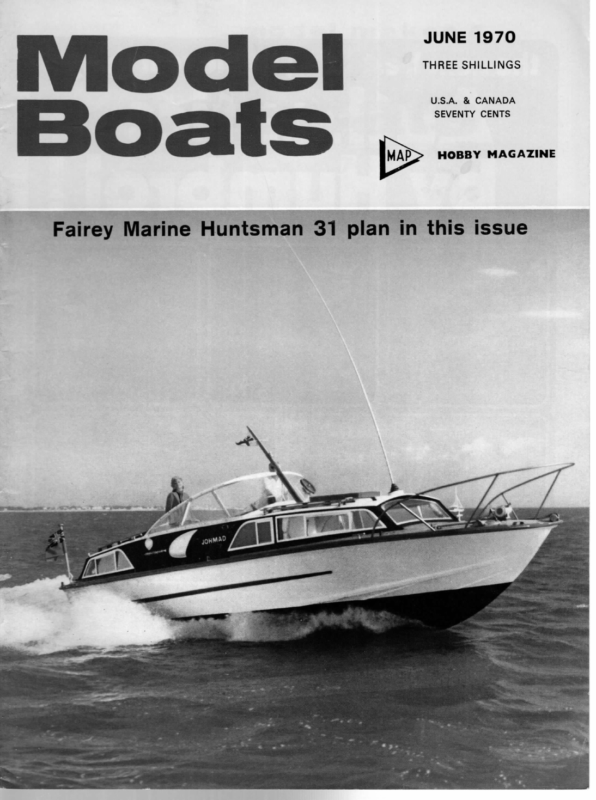
THREE SHILLINGS IWI@ cael = © at & JUNE 1970 foe U.S.A. & CANADA Be HOBBY MAGAZINE Fairey Marine Huntsman rot plan in e Hs er ~
JUNE 1970 ACING MODEL YACHT CONSTRUCTION We believe that this extended series will prove to be among the most valuable yachting material published for many years BY C. R. GRIFFIN PART ONE OME years ago when I started my first model — & ee ae: yacht, I was astonished to find that there was a distinct lack of up-to-date information published on how to build these boats. Apart from ‘Boat Modelling’ (6/- a copy, worth every penny of it) and Daniels & Tucker’s ‘Model Sailing Yachts’, there was almost nothing in print to enable a novice to build a boat to the standards required in the model yacht racing world. Only by constant and persistent questioning of others and, more often than not, the trial and error method, could one arrive at a_ satisfactory answer to the many problems that beset the erstwhile builder. To try to remedy this situation I have decided to record some methods of construction. It is not implied that these methods are the only ways to build a boat, nor is it advocated that they are the best. All that is intended is that they will enable a be- ginner to make the decision as to how he will build a particular design of boat, bearing in mind his own capabilities and facilities. These notes are primarily intended for the novice builder and the writer in no way decries the building of boats for pleasure sailing. However, it cannot be over-emphasised that there is a distinct difference in sailing a model boat for the pure love of sailing and building a model racing yacht intended to be used in competition against other model racing yachts. The former is a delightful and rewarding hobby but the latter, whilst still giving both reward and pleasure, demands more stringent attention to certain factors involved in the building process, e.g. weight, robustness of fittings, and good design of both hull and sailplan. The reader is, therefore, asked to decide which of these two aspects of model yachting he prefers and to interpret the following articles in that light. Alternatively it would not be ill advice for him to read the articles and then make the decision. There are four main classes of racing model yachts, viz. ‘A’ Class, 10 Rater, Marblehead 50/800 and 36R. Select one of these classes. Preferably contact the nearest model yacht club to enable you to select a class of boat that is sailed locally. Should you prefer to go it alone, bear in mind one needs competition to test the boat. Having decided what class of boat you want to build and studied the rules concerning that class, then select a design. To a large extent the chosen design dictates the construction method, especially if one chooses a design of very recent publication. In the following articles the methods described will be those used to build model yachts to the Marblehead 50/800 rule, although there is no reason, in my opinion, why these methods could not be used for the other classes. Heading picture shows one of the author’s Marbleheads and, left, the boat in frame on the building board, ready to begin planking 235
Basically the construction methods may be divided into four main classes, viz., 1. Carved hulls—‘bread and butter’ laminations. 2. Coated hulls —final hull or for moulding. 3. ee planked hulls—round bilge and hard |Woterline _ SECTION SPACINGS chine. 4. Fibre glass hull forms— bought and built up. 80W nex | ——__INWALE Mast + 7 Before elaborating upon the different methods, it would be as well at this point to make some general remarks which apply to any of the methods later described. In the first place, the type of model envisaged does require accuracy of construction. As accuracy and speed are not necessarily stablemates, one has to consider the amount of time one will be able to devote to building and consequently what method to adopt. Whilst on the matter of accuracy, it cannot be over-emphasised that in order to obtain a true and faithful reproduction of the design, all drawing of datum lines and tracing of sections must be done as accurately as possible. Secondly, use only good quality materials; cheapness or second class materials do not help when one is building boats. Thirdly, and probably the most important, do not put tool to wood until one has thoroughly studied the plans of the model and decided how you are BACKBONE TRANSOM BLOCK r. RUDDER Upright FIG 1a FIN FOR SLIDING HATCH AND BACKBONE MAST MOUNTED -.< _ SLOT FOR BACKBONE SHADOW SECTION 4 ALTERNATIVE FIN FOR BUILT-IN HAND GRIP AND DECK MOUNTED MAST NOTCHES _ FOR INWALES SHADOW MOUNT BUILDING BOARD —— k 5 LEG if reqd ALLOWANCE si FOR es = i+ INWALE Sy | \ 1 \ Bees “cas aaa ay x aee 3 XY silly, but consider how one intends to mount the mast, i.e. slot in deck or deck plate, what kind of vane gear and where one is going to put it. Sliding hatch or hand grip, etc. All these matters should be decided and sketched into the plans before one starts building. This not only saves time in the actual building but may prevent the necessity of redesigning a part of the boat because that particular point had not been thought of at an earlier stage in the construction. Lil tee piece | FIG 2 BODY PLAN — | PLANKING | going to build every part of the boat. It may sound J i =f ‘ig YJ man eee, BAP BACKBONE iy ate fig ne ee ee -———] ee Hull Type I - Carved Alternative layers of wood and glue, ‘bread and butter laminations on the waterlines or the buttock lines. This type of construction is adequately dealt with in either of the two books mentioned previously. There is little one can add either to up-date the information or. improve upon the methods described. Personally I believe that carving a hull from a ‘block’ does not suit the modern racing model yacht. In these days when the trend is towards lighter displacement boats, this method tends to give too heavy a hull. The method does suit the MM Class yachts, but so far as I know this class has not really caught on with competition skippers. Lh asI naw Below, Shadows set up on a building board. These are actually for a 10-rater, and although the notes refer basically to Marbleheads, the most popular class, the principles remain identical for any class yacht. Hull Type Il - Coated This method was used in the construction of Stan Witty’s Bambi, and both a ‘final’ hull and moulded copies are being sailed at the present moment. For use as either a male plug for subsequent moulding of glass reinforced plastic hulls or as a final hull. As a foreword to this method, a word of explanation is necessary on the two suggested uses of the end product. Obviously if a final hull is anticipated one has to build in such things as inwales, backbone, etc. (itemised on fig. 1). However, if the intention is to use the hull as a male plug of former from which to take a female mould, many of the internal features can be omitted. To make the explanation easier to follow, the first description will be the method of building a final hull and then the necessary pointers to those wishing to use this method to build a male plug will be given. 236
JUNE 1970 Typical examples of shadows at various points in the hull. Note the top edges extended to a common line, and the mounting strips which are screwed to the board outside the final hull area. The basic idea of this system is the use of balsa wood, which is so easily worked, to produce a framework upon which can be put a layer of glass-reinforced plastic or two-part polyurethane-coated fabric. To be truthful, the rib and plank method is being used but the fitting of the planks is not so accurate. As with any rib type construction method, the first requirement is a building board. This is best made from two pieces of flat block-board, approximately 60 in. long by 12 in. wide by 1 in. thick, screwed together with a further piece of 60 in. x 2in. by 2 in. wood screwed into the middle of the board. This T-shape not only strengthens the board but makes with the front edge on the line. Shadows 7-10 and transom are reversed and again placed with the front edge on the line. This obviates the need to fair off the shadows. Screw all the shadows to the building it easier to hold in a vice. However, should one have to use a table to do most of the work, it is suggested that four 2 in. by 2 in. legs are placed near the board with the screws outside of the final hull shape, then check for overall length. In the case of a Marblehead this must not exceed 50} in. or 50} in. including bumper. The next step is the laminating of the inwales using } in. x ? in. x 36 in. spruce. Obviously the first plank inboard will give a fairer curve if it is of full length, so half joint two pieces together for this purpose using Aerolite 306 glue, a glue strongly recommended for all wood to wood joints. Lay the jointed plank into the recesses cut in the shadows, glueing it at the transom and bow block, both of which have been suitably recessed. Lightly pin the joints and allow to dry. Next glue one strip of spruce and fit it tightly to the plank in position; it can be held there by wooden clothes pegs whilst corners to stop the board rocking. It is important that the true centre line of the building board be accurately marked on to the building board. The section spacings should also be marked at the designed distance and at 90 deg. to the centre line. Ten or eleven pieces of | in. by 1 in. square wood about 11 in. long will be required to mount the shadows (see fig. 2), which are cut from 4 mm. ply. Balsa wood + in. thick and 48 in. long is used for the planking whilst 1 in. thick obeche is used for the bow and transom blocks. The inwales are laminated from + in. x ? in. x 36 in. long spruce and the deck beams, king plank, etc. from 5/16 in. thick spruce. The shadows (fig. 2A), are traced from the body plan (fig. 2) but since each section shows the full drying. Cut, glue and fit another strip of spruce to width of the hull at that point, $ in. allowance must be made for the planking. Cut-outs are made where the backbone and inwales are to be positioned; do not forget to allow for the thickness of the plywood deck. A pointer, on the tracing of the shadows, is to trace from the body plan on to tracing paper the full half section, reverse the paper and complete the full whole section. Then mark off all allowances and notches on this tracing. By using carbon paper it is easy to transfer the finished tracing on to the plywood. It is well worthwhile whilst cutting the shadows to test the shape by using a pair of dividers at various points to check for symmetry. Another useful item is a drilling gauge (fig. 3) which allows all screw-holes to be placed accurately in the shadows and the cross pieces. Having cut shadows for all necessary sections and mounted them on cross pieces, you can then turn to the bow block. This is cut from 1 in. thick obeche and shaped to fit the first section of the body plan at its forward end. It will be necessary to draw a new section for the after end of the bow block, or to cut it slightly oversize and fair it into position. Screw the bow block on to a rough shadow as shown in fig. 4 and fair off with shadow 2, etc. Then cut a } in. deep by + in. wide recess around the after end of the bow block to take the balsa plank ends. A similar method is used for the transom block except that this is made from two 1 in. thick pieces of obeche glued together. I usually hollow the forward piece of obeche in the transom block at the same time as I cut the } in. wide by ¢ in. complete the second lamination on each side. Finally, repeat the process for the third lamination of the inwales, making sure that the joints are not in the same place. The finished inwales should be ¢ in. above the outer edge of the shadows and any discrepancy should now be rectified. Before proceeding to laminate the backbone it is well to consider the fitting of the fin and skeg. Usually the fin is made from ¢ in. thick marine plywood and the skeg laminated from two pieces of 4 in. mahogany with the grain of the wood reversed to prevent warping. Reference to the sketch will show that these are fitted through the backbone and jointed into the king plank. All excess wood is cut away. Fig. 1A gives some variations of the fin depending on what type of mast deck fitting is envisaged and whether or not a sliding hatch or hand grip is fitted. Having decided the type of fin and skeg, cut and shape to size. Using two lengths of jointed } in. x 4 in. spruce, construct a slot to take the fin and skeg, building up with further pieces of % in. x ¢ in. spruce as in fig. 5. This leaves a $ in. deep recess to take deep recess for the plank ends. If a cutaway type transom is desired, this can also be done, but leave enough area to mount the transom block on to its shadow. Position the shadows on the building board at the marked section spacing. Shadows 0-6 are placed 237 the planks. (To be continued) FIN eres FIG3 BACKBONE FORMED FROM. 3x /8" SPRUCE <] SHADOW DRILLING JIG GLOGR SHADOW _ oat — MOUNT FIG 4 INWALE LAMINATED FROM 3x'/8° SPRUCE FIG 5 INWALE_& BACKBONE FOR BALSA=SHEATHED. CONSTRUCTION a = Xs 2 RY FIG6 CHAINPLATES = a = < | EE 80W BLOCK MOUNTING
MODEL BOATS C. S. GOULD DESCRIBES THE THOUGHTS BEHIND AND METHOD OF CONSTRUCTION OF HIS LATEST R/C MODEL MISTRAL 60 in. L.O.A. FREELANCE R/C YACHT Vi Y first attempt at designing, the freelance yacht Chinook, proved to be fairly successful, being faster than Blue Glass, and when fully tuned, in a moderate breeze as fast as an ‘M’ on beating and reaching, but in light conditions relatively dead. With this in mind, a few ideas were put on paper, based on a double chine, also having read Eric Tabarly’s book it was firmly decided that the 1970 boat would be a double chine with moderate Vee. The next question was size, and this was soon resolved; after all I did suggest a 60 in. class so why not try one? The L.W.L. was arranged to come midway up the second chine at mid section, and an increase in beam over Chinook to 10% in. at deck level and a shallower Vee angle gave a ballast weight of 174 lb. This is carried on a fin eleven inches deep from the U.S.K. The fin is of special quality mahogany ply scrounged from a friend who is building a 25 ft. yacht, the leading edge being rounded off to a laminar flow shape and the lower half of the rear edge trailed off fine. With Chinook it was found that there was a sluggishness in coming about, and this was improved by removing about 8 sq. inches from the rear edge of the fin and re-arranging the mast position with no loss of straight sailing ability. With this consideration in mind a delta shaped fin was designed for Mistral, with a trim tab of 6 in. in depth operating from the rudder servo with a variable crosshead position to give similar or differing angles of attack to the rudder, These angles are colour coded for easy reference and alteration. It was expected that the hull weight would be a little more than Chinook, but gouge work on chine battens, keel, nose and stern blocks (these made from yellow pine) combined with thin deck beams and 1 mm. ply deck, a finished hull weight of 4 lb. 12 oz. was obtained, a gain of 3 oz. excluding fittings. The bow shape is more rounded than Chinook and is, I think, worth experimenting with. There is a school of thought among some boffins at the moment of the opinion that if the bow wave can be prevented from breaking a certain amount of power can be saved. I would imagine that this is a very difficult problem, allied as it is to speed, and one which may well be worth comment from readers more knowledgeable than myself. The late Bill Daniels’ early short W.L. 10s had an almost semi-circular bow section with no sharp point of entry at the water line. Although my own conviction is the ‘thinner the better’ for sheer speed, as in the shape of a destroyer, in a yacht, of course, one has to think of reserve buoyancy, etc. It is worth mention in passing that there are two of these yachts being built, one other by a club member, which will have a slightly longer W.L. and a sharper entry and delivery, and this coupled with an identical sail plan should make an interesting comparison of the bow wave theory. Construction followed the normal routine for a chine hull, i.e. dummy bulkheads were cut out of thick cardboard and reinforced with strips of wood and then set up on the building board at the appropriate positions. The first and last are cut from : in. ply and the keel and chine battens bonded into their slots. A minor difference was made by cutting the ply skin, which had a natural curve in it, so that the bottom and side had a slight convex curve in them, about { in. over one side of the Vee bottom amidships, giving a slightly rounded appearance. Rudder and trim tab post are from Bic plastic pens reinforced with G.R.P., giving a light and corrosionfree tube with the correct size bore for + in. internal brass tube spindles. This adaption is rather interesting as M. Bic is a yachtsman who owns, I believe, four Twelve Metre boats and is the man behind a possible future challenge for the America’s Cup. The 244
JUNE 1970 whole construction was bonded with epoxy, screws only being used for fittings, which are of stainless steel and aluminium. Painting has been varied this time, the whole deck being treated with six coats of white Humbrol rubbed down with 500 wet and dry; the hatch openings were cut out last, then waterways and deck planks marked, this time using a laundry marker pen which proved less troublesome than the draughtsman’s pen and indian ink used previously. The kingplank is dark brown. The hull was primed with varnish and given one coat of light blue, bath trials were then held and the W.L. marked, then three coats of Graphspeed were applied to the underwater body. This then had to be rubbed down and burnished. At the M.E. Exhibition one or two interesting points came to light; firstly, we apparently were not the first in 1969 to realise the value of this, as was evidenced by the one and only Class yacht on view; secondly, I noticed that this fine 10r had a full battened mainsail — strange I got kicked by the experts for suggesting this? Incidentally, ‘Classless’ yachts outnumbered ‘Class’ yachts about four to one. With regard to Graphspeed, which is the ultimate in slipperiness next to the Polymers, we have found that a more successful application can be made by thinning and spraying as this method requires less rubbing down and burnishing. It would be interesting to obtain a tank towing test using two identical hulls treated and untreated, as the difference in the friction between this and burnished paint is amazing. A crude static test was done on a sample piece of mahogany treated as the hull and a polished perspex ruler, and I would respectfully suggest that not many boats have as good a finish as the latter. The test load was an office eraser which had a fairly high coefficient of friction. The results obtained were as follows:Perspex: Graphspeed: Angle of rule to induce rubber to move 25 degrees approx. Angle of rule to induce rubber to move 18 degrees approx. After this ‘dirty’ job was completed, two more coats of blue were applied above the W.L., then a gold boot topping line about } in. wide plus a thin gold coving line was added. The gun’l capping is only painted on this boat, saving a couple of ounces. The deck was then given its final two coats of varnish, rubbed down and polished. The sails have been based on a special suit | had made for Blue Glass with a fairly large jib and two full battens in the main, these are in ‘Q’ proofed terylene by Nylet. As has been remarked previously, it is surprising that in view of the number of R/C boating enthusiasts there are, also the simplicity of fitting (we have the control of the rudder only, or trim tab and rudder) this type of sailing has not grown more (classless boats excluded, of course). The number in our own club competition in 1969 was 12 boats and this year a possible 18 boats are likely to enter, ‘M’ and classless, and I will here make a prediction that an ‘M’ will win the cup closely followed by ! Should any club or sailing enthusiasts be Latopested, expert or not, they will be welcome to come along and see one of our series, but as our water is semi- private, near Upnor Castle, it is requested that you contact our sail secretary to arrange for entry. The sail secretary is K. Rosswell, 7 Hornfield Cotts., Harvel, Nr. Meopham, Kent. Last year heats were sailed of three boats at a time doing three laps round a triangular course. This gave an average of six races to get through on Sunday afternoons, there being seven complete rounds to count for final points total. These were run off at about one month intervals—many unofficial ‘races’ of course took place on the Sundays in between, and as we were blessed with a good summer great fun was had by all. After a wait of some two weeks after completion a trial sail was held on 28th December; again, this was curtailed by a bitter east wind, but suffice it to say, lest I offend someone, that with the mast set in the centre of a 5 in. slide, sails set for a beat, and a close reach, and rudder at midships, quite a good course was made. There was a slight tendency to come up to the wind but as the jib began to flutter she paid off. The rudder switch was pushed and she was returned to the bank and the jib moved forward about } in. on the rack. The rudder max. when switched was set at 35 deg., this being the optimum, trim tab at 14 deg. During this adjustment a hook was successfully introduced into a numb thumb and it was decided that this was good enough for a maiden run. A further trial has since been run and for a quick turn to tack or jibe the trim angle has been set to 24 deg. Quite a good turn of speed was obtained, but until it is tried against a good ‘M’ I am reserving my judgment. Table of weights is as follows :— Hull and fittings 5 lb. 4 oz. Mast, Rigging, Booms and Sails 21b.4 oz. Lead Ballast Be 17 lb. 8 oz. 245 Radio and Servo Total Se oS ite as sic. pics eekelDe Sel


