- WING DING From Australia comes an account of an experimental R/C M. is it the first, and could it be registered? Designer/ builder T. D. Seabrook would like to know!
- Two Years a Winner Mike Harris provides the story of ‘Krakatoa’, the 10-rater yacht which won the 1973 and 1974 National Championships.
- MOONRAKER Concluding our notes on building up the Marblehead Yacht available in Kit form from Nylet Ltd.

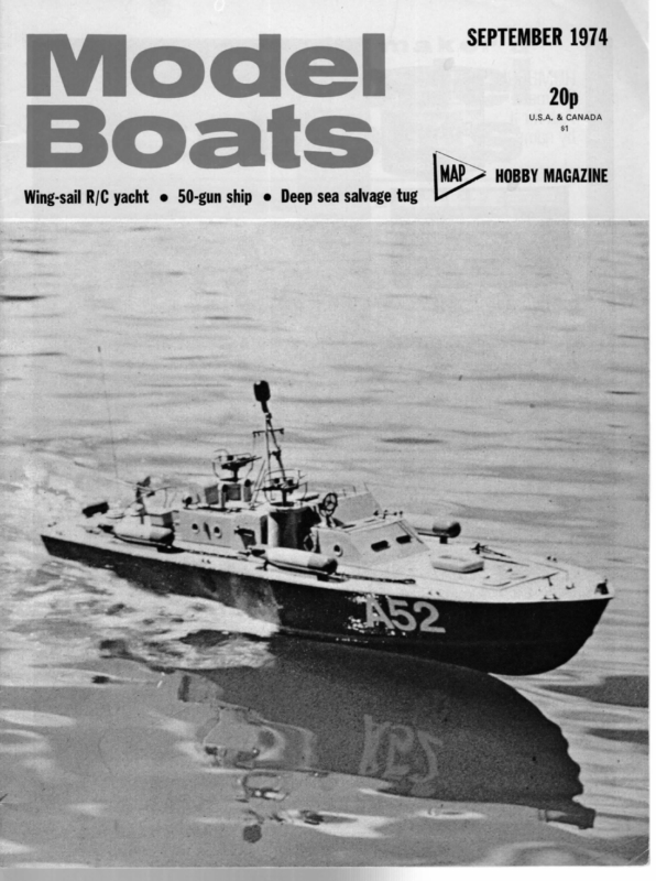
ae 3 — L Wing-sail R/C yacht e 50-gun ship e Deep sea salvage tug SEPTEMBER 1974 ” me HOBBY MAGAZINE
MODEL BOATS WING DING From Australia comes an account of an experimental R/C M. is it the first, and could it be registered? Designer/ builder T. D. Seabrook would like to know! sulted in his loaning to me an old M HE Wing Ding story began in March 1973 when, in quick succession, an 8-foot span conventional slope soarer, and a 7-foot span tailless slope soarer, both own designs and good fliers, were maliciously and severely re- to have radio fitted. class of his (Viking) After much thinking and making on my part, there appeared Viking R/C sporting a proportional winch a la Jeffries Mexico system (RCM&E November 1971), and proportional rudder. After resolving a few trim set problems, we had a very workable boat, much to the chagrin of the ‘knockers’ and pleasure of the protagonists. Our success prompted several other interested glider rebuilders to “have a go’. Also, I decided that it was absolutely essential that a boat of my own be built. Also, styled by a passing tree and a passing hillside, respectively. Knowing that the best consolation and recuperation was thumbing through back copies of RCM&E, out they came. After some time with no glimmer of inspiration, what should present itself but the January 1971 issue. Within its covers, as all devoted fans will instantly realise, was the first article in a series by Bob Jeffries on an Introduction to R/C Yachting. Here, at last, was inspiration indeed! Very little chance of damaged craft or equipment due to functional failure of the nut holding the control stick! That and the subsequent articles were read and reread about this time, regular purchase of Model Boats began. Further discussions with Jack revealed that he had in his possession MAP plans for Witty’s Hammer (Plan No. MM/832). Despite Jack’s insistence that anything smaller than an A was just a plaything, work was begun on Hammer. The hull was built up from 5mm.-wide planks of§ in. balsa, glued with balsa cement, allowance being left for a 1.5mm. grp. skin on the outside. Next time I think of doing that, | won’t. Maybe it was due to inexperience with grp., but I finished up with a disgusting lumpy mess that took many hours of filing, filling and sanding to produce anything like a fair surface that fitted the templates. During the foregoing period, the decision many times. Memory stirred and recalled that there existed at my place of employment (N.B., not necessarily where I work) a person who was reported to be interested in model yachting. This person was one Jack Wheadon, who may be known to some readers, since he hails from ‘the Old Country’ (my father is a traditional Cockney, although you wouldn’t know it). Many discussions with him re- Above, the structure before decking and covering, and the boat on first trials, Below, the wing structure and detail of the joint. Bottom corner of trim flap since trimmed to clear water on heeling. 370
SEPTEMBER 1974 mount. The deck mount consists of a triangular plate of 4-inch aluminium, curved to suit the deck, and having a machined aluminium socket welded to it. This socket is the mast step. Fixed to the top of the socket is the gear segment for mast rotation — more of that ina moment. An interesting point is that this gear segment, made from 4inch thick dural, is glued on with five minute epoxy. This joint was carefully prepared, and seems very sound. The complete mast base assembly is screwed to the deck, which has suitable reinforcements incorporated in its underside (leaves no holes for water to set in). It should be noted that the wing is completely free-standing, with no was made to fit an all-moving rudder in the interests of greater turning efficiency. I note these have now become the standard, and are called ‘spade’ rudders. About this time, my eye fell upon an article in a magazine on full-size sailing, in which a catamaran called Miss Nylex was described. This craft was unique in that she had a rigid wing for a sail, the wing being rotatable, and having large trim tabs on the trailing edge. The report was that she was highly efficient to windward, and not quite so good downwind. With my ‘whynot’ cap firmly askew, and many references on hand, the slide rule bashing and doodling began. The design that emerged consisted of a symmetrical section wing of 800 square inches nominal area, being 66 inches high with base and tip chords of 21 and four inches respectively. The airfoil chosen was the symmetrical section shown on the plans for the slope soarer Omega (RCM&E, July 73). This was modified by cutting off the trailing edge at 90 degrees chord, and adding a hinged straight tapered extension, producing a total chord of 1.35 times the original airfoil. It sounds complicated, but staying. Wing attitude control is by two servos buried in the base of the wing. One is a standard radio servo, and controls the trim flap. The other is a Jeffries winch mechanism, but with no proportional feedback (pity, that). It is, perhaps, worth pointing out that this winch is made from a ‘toy’ electric motor, slot car spur gears, and worm gears from model railway sources — a truly cosmopolitan mechanism! The output shaft of the winch passes through the base of the sail through an O-ring seal, and carries a 12 T pinion. This pinion is arranged to mesh with the segment of 180 T gear fixed to the deck mount. The rotation winch is controlled by a switcher mounted produced a thin section (7 per cent), which could be adjusted from symmetrical to under-cambered in either direction. After examining the moments of areas of the top suit of sails as appearing on the Hammer plan, the Radio installation in stern. Servo on left is rudder, that on right switcher for wing rotation. Receiver is tucked behind rudder post and aft are batteries for rotation servo. On right, rotation servo shown outside but level with its installation position. Other servo controls trim flap. on a standard radio servo located with the rest of the radio. Thus, mast rotation is positionable, but not proportional. The decision to do this was forced by lack of room in the wing for a ‘Mexico’ winch, however, since sailing trials, the grey matter is very active on the problem rotation centre or ‘mast’ location was positioned at 38 per cent chord. This enabled the mast location on the hull to remain as on the plan. It was decided to make the wing in two sections, the join being at 18 inches up from the base. This was done for ease of transport, and also, it made the top section 48 inches, handy for balsa lengths. The wing is made in standard construction, i.e., 4 inch full-depth balsa spar, =5- inch ribs, =4- inch L/E sheeting, but no rib caps, L/E and T/E tapered to suit. The joining of fitting proportional control. tongue is of some interest. It is of –inch half-hard aluminium (not dural), and has its ‘width’ set in the direction of maximum load. This means that it is set across the thickness of the section. Reference to the plans for Stratus thermal soarer (RCM&E, July ’73), will show details, although I modestly claim to have been using it for about two years before I saw Stratus. The advantages are lightness, great strength in the direction it is needed, and great flexibility in the direction needed in the case of rough landings. If the tongue gets bent, you just bend it back again, plug wings together again and fly on (hopefully). Anyhow, back to Wing Ding. The mast is a piece of 1-inch diameter by -4;–inch wall aluminium tube, set in a fabricated aluminium deck 371 During construction, a careful check was kept on total weight and fore-and-aft balance. Probably due to ‘factor of ignorance’ overdesign, the complete wing sail system finished about 1 Ib. over weight, as originally designed for Hammer. This weight is located somewhat forward of the c of g, and necessitated the radio and winch batteries to be located at the extreme stern. This proved a useful location in that the rudder linkage could be kept short and below deck, and everything could be reached through one hatch. This hatch is screwed down and has the screwed lid end of a plastic vitamin pill container (had to keep going somehow), mounted in it. Thus, access to radio on/ off switch and charging plug is easy and quick, while greater access needs a screwdriver. Radio, by the way, is OS DP3 (3 channel) vintage °67, still going well with nil maintenance, despite many sudden decelerations. Because the wing had to be removable for transport, the
Triangular deck mount, rotation gear segment, and mast are clear in these pictures, Rotation servo is hidden in wing structure but flap servo and linkage is visible. Builder is a mechanical design engineer and has obviously put a lot of thought into this set-up, It would be interesting to see trials in a Fleetwood-type blow! electrical connections had to be capable of being disconnected. Problem — how to keep the connectors dry? Answer — another pill container (not mine this time — my wife’s tranquillizers). This had an aluminium tubular body, and a snap-on plastic lid which was airtight. The leads were routed along the inside of the hull, through the bottom of the aluminium body, sealed with contact cement, and sockets attached. The aluminium tube was then glued into the deck, leaving enough protruding for the cap to fit. The leads from the wing were passed through the cap, sealed with contact cement (handy stuff, that) and had plugs attached. Thus, connections can be made, the whole lot stuffed in the aluminium tube, the cap snapped on, and the works are watertight (I hope). The wing was covered with white Solarfilm, trim was red Solarfilm, and the painting of the name was courtesy of my father who is a commercial artist. I will not go into detail on finishing the hull, since I may start crying as I recall all the troubles I had. Suffice to say that it now has a smooth, shiny green finish (that will please Bob Jeffries), with red trim and is the envy of all the local boat boys — ‘nuff sed!’ Having produced such a slippery hull it was necessary to fit a handle to prevent dropping it. However, that eventuality had been allowed for with a substantial deck beam at the c of g, so a handle was formed from 4-inch aluminium rod, and glued into ‘appropriately located’ (good term that — hides a multitude of problems) holes, using five-minute epoxy. At long last sailing trials day came (4th May, 1974). The Gods of Sailing were kind and produced a sunny day with about five knots of breeze. Family, friends and selected interested parties gathered at our favourite sailing spot, which carries the truly Aussie name of Patawalonga. All systems checked A-OK, so we put her in the water. Wonder of wonders, it floated (I already knew that from the flotation trials, stupid) and, more importantly, she moved! 15 minutes later, we were all very pleased and excited — the experiment was a success — she did all the things she should. Then I threw in the coup-de-grace. A bit of judicious rudder and wing waggling and, lo and behold — she sails backwards! Nearly as fast as forwards, too! Not sane a fore-and-aft rig, and handy for getting out of weed. Seriously, the project has been a long and demanding one, but has proven well worth the effort. The only sailing problem encountered has been total loss of orientation of the wing when at a distance. Hence the current project of getting proportional control of wing rotation. I am very grateful to all those who helped along the way, particularly my wife, who tolerated with a smile the late nights alone, the cursing and the mess, and still encouraged me to continue; Jack Wheadon, who started it all, and was there to see it sail; and the fellows in my workshop who did the ‘foreignys’ that I couldn’t tackle at home. * * * Some weeks elapsed before it was possible to make any comparative sailing trials, since there appears to be only one other RM boat in South Australia, and the owner was not available to race. The boat is a Daniel’s Festive, fitted with proportional rudder and synchronous sheeting, and we eventually managed to arrange a sail to compare performance. After spending a very pleasant sunny Saturday afternoon, during which the wind stayed at around 12 knots for most of the time, dropping back to around 5 knots as evening approached, the following points emerged: (1) On any given tack, reach or run, there was nothing in it, correct setting of sails being the deciding factor. In other words, we each made about the same number of mistakes! (2) On rounding a maik, the conventional rig was far superior. The mechanical wing attitude control took far too long to ‘come over’. (3) Wing Ding heeled about 5° less than the Festive, but it is a matter of conjecture as to whether this was due to the Wing, or the deeper draught of the keel weight on Wing Ding. (4) Wing Ding pointed marginally higher than the Festive, but had to be kept up close with the rudder. Thus, the rig will have to be moved back. The trim tab had a marked effect on pointing, needing maximum deflection to windward to get any drive when pointing high. (5) Determining wing orientation when at a distance was impossible. On two occasions, the drive ran right off the rack, causing the wing to weathercock, and necessitating 10 or 15 minutes of most unseamanlike manoeuvres to reengage. Stemming from the foregoing findings, work is now in hand to produce a proportional winch which will be rigged to control the wing by conventional sheeting. The rig will be moved back, and an attempt made to reduce weight closer to the original design for Hammer. I have some ideas for producing a more efficient wing/flap sys- tem, but not yet firm enough to commit to rebuilding. Any- how one change at a time is a good thing. 372
Two Years a Winner Mike Harris provides the story of ‘Krakatoa’, the 10-rater yacht which won the 1973 and 1974 National Championships. Mike, near camera, sailing Wally Jones in the 1973 race at Witton. URING the 1972 season I had become involved in the sailing of a Dicks’ Shallah design 10R and had campaigned it quite successfully in most of the Midland and Northern District Open 10R events. The sailing of this boat was to culminate in the 10R Championships at Hove in the September of 1972. At two of the open races at Fleetwood I had competed against three Cracker designs. One was Mustang, a beautifully-built boat by Jim Major from Birkenhead, and the other two were Sabre and Scimitar, built and sailed by Keith and Sally Armour from Bradford. Mustang and Scimitar had the backward raking fin as suggested by John Lewis in his Model Boats design article which accompanied the publishing of the design. Sabre was built to the original design. All three boats were very competitive, Mustang being particularly good in a hard top suit beat to windward. Suddenly, out of the blue, a letter was published in Model Boats which condemned the Cracker design as uncompetitive and unmanageable and, worse, suggested that the designer was ‘conning’ people by producing a poor design. Having had two ding-dong battles against the three Northern Crackers, I was somewhat amazed by the letter. I wrote a reply which was published. At this stage I had no intention of building a new 10R. I had helped Keith Armour with some tuning problems on Scimitar and had made him a top suit mainsail out of some 4.5 oz. cloth which was very well woven and close wanted a light hull I asked Keith if he would lay the boat up as follows: Hull Keel Mustang’s only problem was that she was slightly overweight and longer on the waterline than designed. After the 10R National I decided that I was going to have a Cracker. Keith Armour had offered to make me a hull earlier in the year but I had declined, now I was sure; I wanted one, but it was to be built my way. The Building Keith Armour’s mould is very large because he had in- corporated the fin and the skeg into the moulding. How he does it I do not know, but the finished result is superb. Normally, the hulls are laid up in one-ounce mat but as I 4-0z. mat. |-oz. mat. Skeg and fence = __1-oz. mat. WhenI told him this specification he went pale and said he thought that 4-oz. mat was a bit thin and maybe the hull might crack up? However, the hull was duly laid up to this specification and two thicknesses of } in. by 4 in. white pine inwales were laminated to the hull. In November 1972 a telephone call from Keith took me North to Leeds on a carefully-planned business trip. The hull moulding was superb, light and carefully reinforced in selected areas. The pale blue shell was like a lampshade when held up to a strong light. The hull was slid into my car and I returned to Birmingham. The first job was to shape a plywood reinforcing piece to go down the inside of the hollow fin. The top of the ply was shaped to include the base for the mast step and then carried on through the deck to form a carrying handle. The plywood was then Araldited into the hull. + in. by 4 in. pine beams were glued to the inwales and a 4 in. by ? in. kingplank let in down the centre. Two struts were glued in from the underside of the kingplank to the bottom of the hull. These were to take the pull of the forestay and mainsheet. When the hull was being checked for alignment of the fin and skeg it was found that the skeg was out of line at the bottom by about -%- inch, so the skeg and fence were slit on one side, pulled over till slightly out the other way and glued. When the glue was dry the clamps were let go and the skeg lined up fairly well, not quite right, but near enough. A very light birch ply deck was fitted and the hull was complete. The full design weight lead bulb was fitted. finished. The new sail seemed to give more drive and he found that he had distinct superiority when sailing against Sabre. Likewise, Sabre showed better performance against Scimitar when the new sail was swapped over. So it seemed the sail cloth did give more drive. The Championship at Hove vindicated the Cracker design, for although Chris Dicks dominated the fleet with Imshallah and won, the second place boat was Mustang, the conditions being a third suit to top suit broad reach. = = Fitting Out The motto for the deck fittings was ‘the fewer the better, but the ones which are there will be in the right place’. A full width jib horse with jackline control for angle was a must. Also ajib fitting with a kicking strap. Synchronous sheeting was fitted to the running lines with separate beating sheets. The mast was a 4-inch, 18-gauge aluminium tube. A single pair of shrouds were fitted and a wire backstay to help keep the jib forestay taut when beating to windward. A well-made Stollery vane gear was fitted. For the first sail a set of double luff sails were made. The rig was not the one published on the design but one which Keith Armour had originally altered, that I subsequently modified. This used a bigger mainsail and a smaller jib. 380
SEPTEMBER 1974 before the Championships, went to Krakatoa so my mate and I felt we were in with a chance as it was to be sailed on The trial sail was on the Birmingham M.Y.C. lake at Witton. The conditions were a hard top suit run and beat. Oh dear! what problems trying to keep a 4-inch tube mast straight, inside a double luff mainsail! The boat was virtually home waters, Witton Lakes at Erdington. One – moving well, but the mast was bending badly. The double luff mainsail was scrapped and a jackline fitted on the mast. A pair of spreaders were also fitted to the mast halfway between the deck and the jib hoist. A new mainsail was made with sailhooks on the luff and the next trials were fine. No bending mast, just pure drive. The boat was then measured and gosh!, what a shock, bang on the designed weight, but only 63 inches on the waterline. This was a bonus I had not expected; more sail to drive her. I had already noticed that when sailing she was very stiff due, I believe, to the light construction giving a good ballast ratio. The name for the boat, Krakatoa, purely a pun on the design name, was chosen from a list containing such gems as Animal Crackers in my Soup, Crawfords, and Crackers, etc. It is the name, of course, of a volcano which erupted and then sank into the sea. other recollection of events before the Championship I feel worth mentioning: during practice at Witton, one weekend, in a fresh wind, whilst planing downwind, Krakatoa stopped absolutely dead, and stuck in the middle of the lake. Hastily grabbing the club rowing boat my mate paddled out to the boat. On arrival he found that the prognathous keel had hooked itself into the chassis of a pram which had been thrown into the lake. This was worrying, at the speed she had been moving the hull could have been cracked, but a minute inspection of the hull, fin, and fittings, showed no damage except for a small nick in the leading edge of the fin. The light construction had also been proved to be strong enough, although at the time the proving had been worrying, to say the least! The 1973 Championship I do not propose to narrate a blow by blow account of the race but rather pass on the impressions of why I felt we won. Tuning Up During the early trials of Krakatoa | had discovered that during construction I had made a mistake. I had not allowed for much backward movement of the mast, and when I was establishing the best position for beating I found that the mast step was not quite long enough, so the mast was fixed on the last slot of the mast step and I knew that my tuning would depend on how near to the ideal this last hole was. As it turned out it was about = inch too far forward for light weather beating so a mainsail with flow cut into it was made. It also had a shaped piece in the bottom, big boat style. This did the trick, as the extra drive in this sail compensated for the mast being in not quite the right position. The sail angles for beating were the ones I always use for any boat I sail, they are jib 124° to 15°, main between 7° to 10°. So in a light wind the jib is about 15° and the main around 7°, and in a hard top suit beat the jib angle is about 124° and the main approximately 10°. The vane angle varies only slightly, 29° for light winds and 30° to 31° in a fresh to strong wind. Running downwind seemed to be the leg on which the design excelled. She lifted quickly and planed steadily. The number of spinnakers made were in line with the deck fitting motto — ‘a few, but the right shape’. In the early days, when polythene first became readily available, I made lots of different shaped spinnakers for every boat I sailed and consequently, when racing, was never sure that the one I was using was the right shape for that particular weight of wind. The spinnakers for Krakatoa were basically three shapes. 1) A tall, narrow-shouldered sail in 200 micron polythene for running dead before or on a slight quartering wind. 2) A semi-balloon for quartering winds, i.e., not much curve in the top of the sail. 3) A triangular flat spinnaker for reaching. In actual practice, sail number one was used nearly all the time. The spinnaker pole used on Krakatoa during the 1973 season was 1 inch shorter than allowed, due to a moment of mental aberation when cutting the tube to make it. The 1973 Season The season’s work-up to the Championship weekend was purely practice. The Armour team came to Birmingham for a weekend of 10R sailing, where performance notes were swapped. Krakatoa was sailed by my mate in the 10R M.D.C. and came second. He was slightly handicapped by having to sail in top suit in a second suit wind, as the small sails had not been made. All other Club events 381 1) Everything worked properly. The only thing which didn’t was the guying mechanism of the vane but this was subsequently improved by fitting a spring. 2) The wind on the second day tended to swing a little, so to windward if we were ahead I always covered my opponent. If he sailed tack and tack I did, if he guyed I did because a windshift could lose you a heat if you didn’t cover. 3) Our balloon spinnaker seemed smaller than most people were using, but we lost very few runs in the light winds because once the sail was filled it stayed up all the way down the lake, where our opponents’ tended to fill then drop. 4) To help the spinnaker keep filled I always rolled the jib when running. The jib then cannot disturb the airflow across the spinnaker. The 1973 Championship ended in a win for Krakatoa; by the narrowest of margins over Jmshallah sailed by Chris Dicks, with the Armours 4th and Sth. In light winds the design had shown superiority, but as it was a home waters win a few people had expressed doubts as to how the boat would perform at Fleetwood in 1974. Krakatoa was virtually retired for the rest of the 1973 season to allow time for sailing ‘A’ Class, having been ‘revolutionised’ at the ‘A’ Championships by possibly the most dedicated and brilliant skipper this country has ever produced. I spent the rest of the year doing odd club racing. The 1974 Season The lead-up to the Championship was again one of practice, club racing and the Midland District Champion- ship at Witton. Team Armour came south to Birmingham for the District Championship, and the event was won by Keith Armour, not sailing a Cracker, but a stretched-out version of his ‘M’ Class called Blackbeard. The event was sailed in a light reach and to be frank I had problems with Krakatoa. She seemed sluggish in the light winds and she was leaking round the edge of the deck. After the race I took her home and removed the foredeck. The inside of the boat was wringing wet. The inwales were soaking and the Araldite round the keel piece was cracked. The boat was hung upside down over the central heating boiler in my verandah/workshop, for a week. When it was thoroughly dried out the keel root Araldite was chipped out and reglued. The cause of the failure was believed to be because I had used some Araldite which I had had for about two years. It just hadn’t cured properly, and was (continued on page 390)
Will the radio box complete and installed, it is necessary to rig the complete yacht up (quite a conjuring trick single-handed with a deck-stepped mast!) to set up the sheeting system. We followed the insiructions and made a Perspex plate, leading the winch line forward and turning it back to tie off to the piate. Although a pulley b!ock is desirable at the bow to turn the line, it is difficult to buy one casually, but the friction through a screweye is very little more, so we used one. A second was needed to guide the return line away from the deck centre, otherwise the piate fouls the jib rack. A yard of hat elastic ties to the other end of the plate and is made off to a screweye on the deck edge abreast of the rudder. The sheet line runs from a ring (supplied) at the main sheet lead, through the plate (see last month’s sketch) to a second ring at the jib sheet lead. When both rings are hard against the leads the sails should be sheeted right in, so lines are tied to the boom ctips and made off to hooks engaging in the rings, all taut. Now when winched out, the plate moves aft and the booms can swing to full out. The winch motor can be matched to the transmitter key movement by battery supply polarity or, on the Monoperm Super we have used, by using the switch on the motor case. MOONRAKER Concluding our notes on building up the Marblehead Yacht available in Kit form from Nylet Ltd. Since the rudder servo works off the receiver batteries, polarity cannot be changed, but the mechanical linkwork can — simply unscrew the servo output disc, pu’l off, and replace 180 deg. round. Adjust the rudder pushrod to neutralis? the rudder and the boat is ready to sail. We haven’t had an opportunity yet for full trials, but ours was dead on its waierline and enough Moonrakers are now sailing to know that no one is likely to grumble at performance. Although we have made minor criticisms, mostly of points where beginners might be perp-exed, overali we think that Nylet Ltd. have done a good job at a very fair price. A class yacht is difficult to wrap up so that its builder doesn’t have to think; a lot of beginners are already on the water with Moonrakers and we are certain there wiil be many, many more. * * * * The first-2ver National Championship for R.M. class yachts is being run by Guildford M.Y.C. at Elstead Moat on September 21/22, sailing for the new Model Boats Trophy. Why not come to see how it’s done? 384
MODEL BOATS BILSDALE (continued from page 364) The railings around the promenade deck were difficult, just as those around the bulwarks were easy. My first attempt was a failure of the first magnitude. I epoxied household pins into holes drilled in the correct positions around the deck and then tried to solder on the three rails. This proved to be impossible on two counts, one that the heat from the soldering iron carried along the pins and unsoldered previously-soldered wires and two, the epoxy could not stand up to the heat and everything fell lopsided. After much muttering I ripped out all the carefullypositioned pins and sat down to think. It was my wife who casually suggested that the best way to accomplish the task would be to do the railing in sections, each section being assembled on millimetre graph paper to give an accurate line up. She was, of course, perfectly correct and the task was completed relatively easily. One tip I did pick up here was to brush each joint with Bakers’ soldering fluid, even though I was using resin-cored solder. This makes the soldering much easier and gives a neat joint as a bonus. A trim with the wire cutters on all the uprights and a mahogany capping strip finished things off nicely. Lifeboats. Now these started life as scratch-built plank on frame gems and finished up as cardboard mouldings from the local model shop! Let no more be said. The covers were made from part of an old, thin, handkerchief, dutifully shaped by my wife. Two coats of dope tightened everything up O.K., and a coat of slate-green paint gave a good canvas-like finish. Grab lines were also fitted by my wife. These were constructed from the head-ends of household pins and green shirring elastic. A pair of tweezers and lots of patience were required here. Davits were knocked up from piano wire and dowel, shirring elastic being used for the rigging; once again my wife’s nimble fingers were very useful. Now for the ladders. The one from the promenade deck up to the bridge was by courtesy of Messrs. K.K. (I think). Those at each end of the promenade deck I hope look identical. One was a period ship-type kit, bought from the local model shop, the other was scratch-built from a piece of very similar grained wood, when the model shop sold out and could not obtain further supplies. Portholes, bollards, anchor winch, etc., were all commercial items. The portholes were sealed from the inside with polystyrene cement to stop the ingress of water. The mast was turned from a bar of aluminium by my friendly turner, who informed me in not so subtle tones that it was not particularly easy, due to whipping. Rigging was completed with white shirring elastic to eliminate sag. At this stage the model was ready for a trial, so up to the bathroom. Disaster, with a capital D, the model was completely top heavy when ballasted to the water line. (Yes, I had got the ballast right at the bottom of the hull.) Even when ballasted to 4 inch below the water line the model was extremely tender. This really took the wind out of my sails, I felt completely deflated, all that work for nothing. I experimented with all manner of ballast positions and finally came to the unfortunate conclusion that an external keel would have to be fitted. The first keel was simply a piece of 34-inch aluminium of approximate measurements 5 in. by 4 in., with a suitable amount of lead cast and screwed onto the bottom. This was not large enough to hold the model upright in gusty conditions and a second keel was, therefore, fabricated. I estimated a size of 9 in. by 6 in. and fortunately this proved to be just about right. (You can’t be unlucky all the time, can you?) As can be seen, I made the keel detachable so that when on display at home the model is aesthetically more pleasing. I would be pleased to hear from any other builders of this particular model to compare notes with them on the problems of stability. The final move, to date, was the fitting of signal flags, made from paper suitably coloured with felt-tipped pens, showing S.S.M.S. (our local club initials) 1974, and PYU (Bon-Voyage). A wicked comment from some people to the effect that I should fly merely ‘D’ (keep clear, I am manoeuvring with difficulty), was treated with the contempt it deserved. Well, that just about wraps it up. No doubt some of the purists will be having hysterics and to them I offer my apologies. The above narrative, however, relates how J did it, I enjoyed it and to me that is what matters, now I can turn my attention to my beloved model railway and yet another scale-model boat. In conclusion, may I thank all those people who have helped in one way or another, particularly my wife, who has not only borne sawdust on the carpet and glue in her hair with such good spirits, but also completed a fair old bit of modelling herself. (Since completing these notes Mr. Goodyear has won the Yorkshire M.P.B.A.’s Bill Fox Scale Trophy for the second year, against some very good opposition.) TWO YEARS A WINNER (continued from page 381) quite brittle. The hull was also stiffened close to the keel by gluing three small ‘fibre glass’ tubes across the hull. These tubes were made by soaking newspaper in fibre glass resin and then rolling it into tubes. The inwales and beams were given a coat of thin varnish to seal them and a new deck fitted. A quick trial in a light wind before the Championship showed an improvement in performance. The 1974 Championship My thoughts before this race were that I didn’t expect to win for several reasons. a) I didn’t think Krakatoa would be very good on salt water because of her shorter waterline than designed. b) Imshallah. c) Mustang. On reflection b) and c) should really come before a). However, Krakatoa did win and proved competitive on salt water. After dropping 12 points on the first day, which was pretty grim, I dropped only two points on the second day and 10 on the final day. There were more Cracker designs at the 1974 Championships than in 1973 and they filled first, second, fourth and fifth out of the top six boats. In both Championships I had the element of luck without which it is even more difficult to win, but the boat’s design helped to overcome most of my mistakes. It is an easy boat to sail, which does help. Krakatoa has now been ct to a southern owner, and I am sure he will also do well. I am building a new boat with which to defend the Championship in 1975, and whilst writing this article have been trying to design some new deck ‘hardware’ to help give me the slight edge that is required to make a good boat a Champion. Finally, as usual when writing, my pen has run away with me so I should like to thank Team Armour in Leeds, who built the shell of Krakatoa, Harold Dovey, who helped me finish the boat, and my overweight mate who still wants to sail with me regardless of the abuse I pour on him! T hope this article will prompt more people to exchange ideas on construction and tuning because there are not many people who can do it all and sail well. I know I can’t. 39)


