- POOLE’S 25th ANNIVERSARY Trevor Reece talks about the club and covers points about radio yachting in general
- PULSAR A new 10-rater design specifically for radio, by the most experienced designer in the class, John Lewis
- RADIO CONTROL YACHT RACING Concluding Charles Brazier’s guide to the rules. The reader is Red and Charles Blue.
- PACEMAKER Resuming the construction of a radio-controlled 10-rater yacht from the Nylet kit.
- Readers Write….

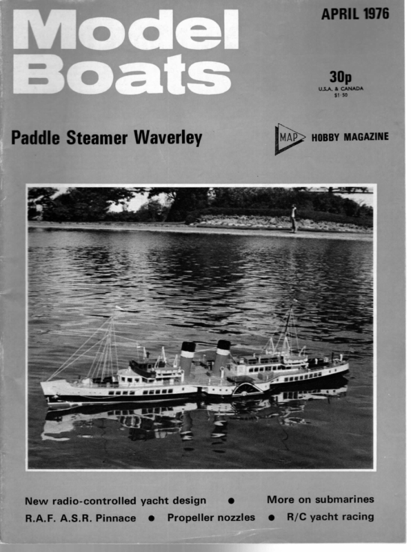
APRIL 1976 30p CANADA & .A. U.S $!-50 HOBBY MAGAZINE Paddle Steamer Waverley New radio-controlled yacht design R.A.F. A.S.R. Pinnace @ ® Propeller nozzles More on submarines @ R/C yacht racing
MODEL BOATS POOLE’S 25th ANNIVERSARY Trevor Reece talks about the club and covers points about radio yachting in general Celebrating the anniversary during the mesting – scorer Henry Chaney, the writer, and Len Thompson. airflow from the aft part of the sail, but its demise pre- sumes an insignificant contribution to sail power or drive. Alternatively, the MYA rules have robbed us of an efficient sail plan!* Many readers will have seen the ‘Tomorrow’s World’ programme covering ‘slotted’ sails and no doubt some enthusiasts have already carved slots in their terylene sails with a sharp soldering iron. The ‘ television demonstrations were very convincing and it will _ be interesting tolearn of results obtained with model yachts, However, similar results were obtained in the 50s with an ‘annular’ sail which consisted roughly ofa single triangular IN 1975, the Poole Model Yacht Club celebrated the 25th Anniversary of its foundation in its present form and a special event was held last August to commemorate the occasion. A brief review of that time might interest readers, because, when our Club was founded, semiconductors in the form of transistors were not in commercial production and radio control of models was very much in its infancy compared with the sophistica ted systems now available. Much of the early work on RC yachts was pioneered at Poole by such notables as Colonei C. E. Bowden and Mr George Honnest-Redlich, the latter still being a member of the club. Our present Vice-Commodore, Mr Roger Dehon, also contributed to the work of those early days. Commercial multi channel radio gear was not available then and RC yacht racing was carried out one boat at a time, each course being timed. As far as can be determined, the first pair of RC yachts ever to race simultaneously with control of sheets and rudder was at Poole in 1951, when Col Bowden and George Redlich sailed together using the ‘Redlich’ tuned reed system. This subsequently appeared commercially with the well known REP range of reed equipments. Other names which strike very distant memories are ED (Electronic Developments) who produced single channel and reed outfits, the FennersPike mark-space unit, ‘Windy’ Kreulen, who developed several circuits for home construction, and Macgregor , who then produced a variety of kits including the Ivy, Tommytone, Terrytone, and Ivistor series. Some of the early experiments in RC yachts are described in Col Bowden’s book Model Yacht Constructi on and Sailing which was first published in the early 1950s. The following quotation from Chapter 5 sums up the reason for some of our present racing rules: “In practice it is doubtful if more than four yachts can race together, because more than this number cannot be accurately judged by the helmsman, around distant marks, when competition is keen and a fight for a mark develops, with all the advantages to be gained by rounding first’’. One could be excused for thinking that was a recent quote! The most significant changes in RC yachts appear to have been in the sailplan, and in the 1950s the foot of the jib was frequently only 50 per cent of the length of the main boom. This gave a relatively small jib when compared with present trends in which the jib foot is as much as 98 per cent of the main foot. The mainsail aspect ratio is also much higher these days, but some of the earlier mainsails had an elliptical leach, sometimes with full width battens. In theory, the elliptical leach with its very sail pivoting on a line between the apex and somewher e along the foot and having a central triangular hole. Before leaving the subject of sailplans, it may be remembered that prior to the relatively recent use of plain terylene for the sails, they used to be made of ‘Union Silk’ which in turn was made from fine Egyptian cotton. Naturally, one tends to take for granted the more obvious changes but just imagine trying to sail today with radio gear weighing 44lbs. and with a winch having a pull of 90lbs. On second thoughts, it would be better not to imagine it! It was not until about 1955 that the first commercial transistors became available in the UK and my own first purchase was in Cyprus in that year when I ordered two OC70s at £1 each from Mullards. By the early 1960s, there was quite a range of both valve and transistor equipment available and, in some cases, manufacturers used a combination of valves and transistors. Quoting from an advert in RCM&E of February 1962, REP were offering their Dekatone 10 channel simultaneous relayless receiver with 5 servos and transmitter for £95 so even with VAT, present day prices do not compare unfavourably. Not surprisingly, some of the Poole skippers still use radio equipment built in the 1963/64 period using the Whit 63 superhet receiver with reed bank and this fact alone indicates how very reliable they were; reliability being discussed in more detail later on. These earlier receivers typically weighed 5 to 8lbs. including accumulators, rudder servo and winch, whereas the more modern radios in RA boats are nearer 3lbs. all up, using smaller capacity rechargeable cells, light weight rudder servos and a more efficient winch mechanism. All in all it is certainly true to say that we have made good progress in those 25 years of RC yachting at Poole but it is up to all skippers to ensure that our chosen sport does not degenerate to a game in which rules eclipse sportsmanship. There is little doubt that the tremendous increase in popularity of RC yachts is very largely attributable to the RM Class and this is indicated by figures given at the 1975 MYA AGM. The numbers of registered radio yachts at the end of November 1975 were — RA Class a Ee =: 21 RIOR Class… He a 35 RM Class : Z 176 In the RA Class, there are some 30 or more boats in regular use which were not registered at the time, one reason being the necessity for accurate measuring jigs to check the Rating. By this time next year, it is believed that there will be some 60 RA boats registered. *Full battens etc were not allowed at any time in most MYA classes but were never proved superior in, for example, the 10r class where they have always been allowed, full roach made better use of the backward and upward 192
APRIL The figure for RIOR is quite encouraging, particularly as the first RIOR national championship will be held at Poole in September 1976 and this class is expected to flourish, particularly since there are now some very fine kits available, including fittings if required. Of the 176 RMs, 91 were registered in 1975, so it’s a question of words speaking for themselves. Portability, economy and availability in kit form seem to be the predominant factors taken into consideration when choosing a particular class, although the area of sailing water and its environment may well decree only the use of the smallest boats. There is little doubt that for performance, grace, and seaworthiness in sea-like conditions, nothing can better a well-designed RA boat. The same boat could be quite useless on a small inland water. For the benefit of many holiday-makers to this area who accidentally find a yacht in their boot, the Poole sailing water is immediately adjacent to Poole harbour, being separated from it by only a narrow strip of land carrying the main Poole—Bournemouth railway line. With the kind co-operation of the town council, we are given virtually exclusive use of the yachting enclosure at weekends and as it is some 75yds. x 150yds. and approximately three feet in depth, practically any model can be sailed. During weekdays there is very little activity. Those of you who read the reports on the RM National and the RA National may have been struck by the fact that in the former event, there was only one boat which suffered from radio failure whereas in the latter event there was a much higher percentage of failures. Some basic information on the reliability of electronics may be helpful if only to remind skippers to do some maintenance! Reliability is defined as the ability of an item to perform a required function under stated conditions for a stated period of time and those few words have caused many a headache to thousands of people. The ‘required function’ is usually detailed in a technical specification and in our case, for example, we want the assurance from manufacturers that an RC outfit will operate over a certain distance and that interference will not be experienced from adjacent channels. Similarly, a certain movement of the transmitter controls will always produce (within limits) a stated degree of movement for each servo and that the batteries will provide at least ‘x’ hours of life. The ‘stated conditions’ can include all climatic conditions such as temperature, humidity, air pressure, and those conditions likely to be met in service such as vibration, acceleration, deacceleration (e.g. being dropped:on the floor!). Commercially, the ‘stated period of time’ is not normally given but an idea of the manufacturer’s confidence in his equipment can be gleaned from the warranty, typically 1976 circuit boards in transmitter and receiver and examine them for signs of corrosion on the reverse (copper track) side. The area of the transmitter PCB immediately above the battery pack is particularly vulnerable to corrosion from the fumes which are produced by some types of rechargeable cells, notably the button-types of cell which are not vented. In cases of severe corrosion, the board can be cleaned off, using diluted hydrochloric acid and then followed by a cleaner such as Freon or the familiar carbon tetrachloride. The latter usually leaves a deposit which is best removed with an old toothbrush. In the case of the receiver PCB, this is sometimes damaged by the entry of water and this is one of the main reasons for the higher incidence of faults at Poole. We sail in salt water whereas the majority of clubs have fresh water lakes and, as is well known, salt water corrosion can be very severe and extensive particularly to steel and copper — this includes copper wires (on components as well as wiring) and the copper tracks on the printed circuit boards. There are conflicting views on whether the boards should be varnished or not but I always use Stirling varnish type B8 which is available in aerosol cans. This varnish has the advantage that it can be soldered through for repair work, the repaired area then being resprayed. Lastly, on the subject of maintenance, it is very worthwhile to disconnet the gear train of each servo and let the motor run for a few minutes in each direction either by moving the feed-back potentiometer or by operating the transmitter control. It is not unknown for a winch motor to have a shorted turn on the armature (from overheating at some time) but which apparently still operates normally. As servo motors only operate for a few revolutions at a time, it may not be noticeable that the motor is overheating and drawing perhaps twice the normal current. Hence running for a few minutes off load will quickly identify any fault condition. On finally mentioning reliability, it is well worth noting that a high failure rate can be expected at the beginning and at the end of the equipment’s life. In between these two extremes, one can enjoy a reasonable period of fairly stable fault incidents. The early period of failures is usually overcome before delivery to customers by soak testing the equipment at the factory. However, very little can be done in the case of the end-of-life faults and the only certain factor is that catastrophic failures will continue at decreasing intervals until further repair is impossible! In so far as our sailing activities are concerned, 1975 wasn’t exactly the best for wind conditions. I was able to sail through all our events in the top suit only and did not even look at the second suit. The maximum wind strength was approximately 14mph, i.e. a low force 4, one year. Generally, the equipment used in RC models has a pretty thin time of it, considering that it is often carried around in a car boot, subjected to undercharging or overcharging, used in the rain without adequate protection and with consequent condensation, corrosion from salt water or vibration from motors and then very little in the way of maintenance. __NORMAL_COURSE The conditions of use are generally termed the environmental conditions and the more severe these are, the more faults are likely. Extremes of temperature should be avoided; if you leave your outfit in the car or keep it ina garden shed during the summer, damaging temperatures of up to 90°F are easily reached. If you use your transmitter in the rain, fit a decent cover on it; there is one commercially available now (see adverts in this journal). The most troublesome point of entry for rain water seems to be where the transmitter aerial passes through an insulating bush into the case. A smear of silicone grease such as MS4 will help prevent this, and the same grease can be used to lubricate the sliding joints in the aerial. During the winter it is a good idea to remove the printed 193 WIND | | CONTROL POSITION
MODEL BOATS and ideally I would have liked a stronger wind if only to determine the upper limit for my new top suit. However, it was noticeable that some skippers had to change down, which indicates the advantage of a stiff boat with both radio and ballast as low as possible. It was also interesting to observe the behaviour of John Cleave’s Klug RIOR yacht Knut (pronounced ‘Canute’). This design appears to be a hybrid between a round bilge and a hard chine, the forward sections between roughly V shaped and the aft sections, a shallow U shape with a wide transom. Certainly it behaved quite unpredictably in a force 4, exhibiting the sort of instability associated with a hard chine hull when heeled and with its exceptionally deep bulb keel, it is probably designed for sailing upright. Incidentally, John Cleave was elected International Racing Secretary at the 1975 MYA AGM with the hope that he will be able to establish lines of communication with Naviga. Of the nine cup events for club members, five were won by Brian Askell with his RA boat Pele, built and designed by club member Frank Walker. Brian also won the Taplin Challenge Cup and the Laidlaw Dickson Cup, and in the RA National was runner-up to Norman Hatfield and Aubade. The other events were the Queens Cup won by It is a sign of the times that we have had a larger proportion of R1ORs this year than previously, and our club policy is to promote equal activity on both RA and R10R boats. We do not preclude RMs, but in the prevailing conditions at Poole, they tend to compare unfavourably with the larger classes and we give them a 30 second early start as a rule. In conclusion, one small point on setting the course: it is normal practice to lay a triangular course with the start line more or less perpendicular to one leg. For a change, try the course illustrated, as this gives really exciting racing when all yachts are converging together on the windward start mark. Be warned, however, that it is difficult to estimate speeds with the boats coming directly at you. This modification to a normal course was made to give a compromise between a one lap race and a two lap race because of fluky winds. At the beginning of yet another full season, we look forward once more to seeing old and new skippers and boats together with food galore provided by our hard working ladies. They had a new kitchen in 1975 and deserve a mention for putting up with the old one for so long. The refreshments provided not only enhance the social standing of the club but make a very substantial contribution to our gross income. Hence, in thanking the ladies, we also acknowledge that without their help, our subscriptions and entry fees would have to be much aa to maintain our account on the right side of the Len Thompson and Jenny, the Holland Jones Cup won by John Cleave and Knut, the Coronation Cup won by Frank Walker with Swara and the Hogg Cup won by Roger Dehon and Mimi. Based on performance over the year, the points gained for the first five, as a percentage Pho possible points (for the races entered) were as ollows — Skipper B. Askell J. Cleave Yacht Pele Knut Class RA RIOR Points 999 369 Possible 1182 456 ine. PMYC RC Yachting Events 1976 Date % 84-5 28th March 11th April 17th April 19th April 2nd May 9th May 30th May 80-9 T. Reece Giselle RA 641 1022 62:7 R. Dehon Mimi RIOR 699 1118 62-5 J. Gascoigne Suki RIOR 384 648 59-3 Jack Gascoigne, who is now in his eleventh year as our Commodore, was also joint winner with Richard Wright, our Vane Sailing Secretary, when we held our 25th Anniversary event. On that day, pairs of Vane and Radio skippers were drawn and then we held normal racing schedules for vane and radio simultaneously. Unfortuntely, there was so little wind in the morning that the free sailors could barely manage a single run in either direction. We are having another similar event in 1976, as otherwise the two sections of the club never get together and at the suggestion of our new Vane Sailing Secretary, Andrew Webb, we are calling this the ‘Vandio Day’ which is strictly a club S5th/6th June 13th June 27th June 18th July Ist August 22nd August 30th August 11th/12th September 19th September 3rd October 17th October 24th October All events will start set up high drag. It is probably even more important for a radio model to maintain stable flow conditions easily as it is much more likely to be induced to change direction and sailing attitude quickly as compared witha free sailing model under vane control. The stern overhang has been kept short to enable quick turning when at close quarters to an opponent, when long overhangs swinging round can only cause embarrassment. The bow overhang is long enough to provide a satisfactory termination to the forward section of the hull. So the yacht is fairly compact and portable. If the results of the predecessor of this design are anything on which to base one’s judgment, then Pu/sar should this way have not proved inferior to the conventional raked fin. However, the choice of this configuration for Pulsar is deliberate as an attempt to improve manoeuvrability. By bringing the centre of lateral resistance aft and moving the rudder forward I have shortened the turning providing adequate strength is provided, a thinner section may be used. I would not, however, recommend a flat type of fin as this form of section is too easy to stall and Marguerite Cup (3) R10R National Championship Club Race Freeman Cup Club Race Club Race at 10.30am except the second day of the two-day bie not be held this year. All other events are open to RA, RIOR, or (from opposite) fin is too great and in this respect I would not argue that, Hogg Cup Bravery Cup Club Race Coronation Cup events when racing will start at 10am. Entries for the RIOR Champion- suggested for the free sailing Cracker and those built in moment. This should make it unnecessary to have the grotesquely large rudder often seen on poorly designed radio models. A large rudder is capable of being the most effective brake the skipper has, but personally I would prefer to have a built-in drag inducer operating off a separate radio channel if I felt that the ability to stop quickly could prove a tactical advantage. Some people may also think that the thickness of the Taplin Challenge Cup Holland-Jones Cup ship will be via MYA. Entries for the Taplin Challenge Cup will be by invitation. It is regretted that because of the proximity of the RIOR National to the perpetual calendar date, the Laidlaw-Dickson Cup event. PULSAR Event Gist Cup Robert Cup Club Race Marguerite Cup (1) Club Race Queens Cup Marguerite Cup (2) prove to be quite satisfactory and fully competitive. A free sailing version would be quite an interesting experiment too! I will be most interested to get reports back on this design when used for radio control, because it is this information which enables a designer to improve his work and do his part in raising the standards of our sport. 194
APRIL 1976 PULSAR A new 10-rater design specifically for radio, by the most experienced designer in the class, John Lewis Wis the rapidly increasing popularity of radio controlled model yachting there will no doubt be a period of time during which the dimensions and design style of the models will vary considerably. The free sailing designs have developed to a high degree of sophistication and longer waterlines and small highly efficient sail plans are the order of the day. There are, and will continue to be, some adaptations of free sailing models into the radio control field and one may regret to see some of the older designs re-emerging under the new guise. However, the radio controlled model requires to be designed to different parameters in that it must be very easy to manoeuvre, quick to accelerate, and be relatively insensitive to inaccurate trimming of the sails. In general this all means that we need to have larger sail areas of lower aspect ratio on appropriately shorter waterline lengths. For this new design I have, therefore, chosen 58in. LWL and a sail plan of moderate aspect ratio but with a large jib. There will be those who would prefer a large main sail and small jib combination, but until more evidence is available to me I will choose the big jib concept. It should not be too difficult to goosewing the jib on the run and I have little doubt about its efficiency to windward and on the reach. The height of the rig is moderate and the model should not require the precisely accurate trimming that a tall rig requires to obtain optimum performance. I doubt that the precision can be obtained by radio control at the present state of the game, as it is difficult enough for the free sailing model operator. Something more comfortable under gusty conditions is also desirable and there will be reduced need to change down to smaller suits as wind velocity increases. The hull form is similar to the not unsuccessful Cracker design except that the run aft is a little finer and the bow somewhat more powerful above the LWL. The midsection is my favourite narrow, shallow round bilge concept which has proved so successful over the years. The fin keel with bulb is similar to one of the options (continued on opposite page) DRAWINGS FOR THIS EXCITING MODEL ARE AVAILABLE, REFERENCE MM 1214, PRICE £1.15 INCLUDING VAT AND POST, FROM MODEL MAKER PLANS SERVICE, PO BOX 35, HEMEL HEMPSTEAD, HERTS HP! IEE. SHEER AND WATERLINES ARE HALF SIZE, BODY PLAN AND LEAD FULL-SIZE, SAIL PLAN { SIZE DETAILS— LOA. — 71-4″ Lat — 60” OISPLACEMENT21-8 Ibs BALLAST —— 12-O ibs SAIL AREA 12882 5 ing FULL SIZE SECTIONS FULL SIZE LEAD SAIL PLAN %/8th SCALE |MM 1214
MODEL BOATS casualties and little damage. Saumarez had received two hits and lost two men killed. Three other men had been injured. There were no casualties or damage to report from the other four ships. In the excitement of battle mistakes do occur and at one point Virago had come under fire from another ship in the flotilla and had to make by lamp, “‘Please, we’re on your side” before the firing ceased. All in all it was a very happy bunch of destroyermen that, at dawn, rejoined the main fleet for the return trip to Trincomalee. The fleet was attacked by Japanese aircraft during the day, but all attacks were driven off by fighters from the carriers. That evening, however, a further raid resulted in a very near miss on Virago. A bomb struck the water only five feet from the ship’s side, abreast the Bofors platform between the torpedo tubes. Splinters from the bomb riddled the gun platform and superstructure. Five men died as the result of this attack, ironically the most serious casualty list from the whole operation. The fleet arrived back at Trincomalee without further incident, arriving at 0630 hrs on 19th May. Despite the early hour all ships turned out their lower decks to cheer them in. At 1100 hrs the crews were assembled to hear congratulatory messages from King George VI and Lord Louis Mountbatten, the Supreme Commander for South East Asia. Congratulations were indeed in order for this had been one of the best-executed destroyer actions of the war. It was not the first time, either, for Saumarez and Virago: they had both taken part in yet another classic destroyer action in December 1943 when they played a vital role in the sinking of the German battle cruiser Scharnhorst off the northern tip of Norway. Saumarez was damaged by a mine in 1946 and, as a result, was not retained, being scrapped in 1950. The other four ships, however, were all converted to frigates in the early fifties. Vigilant and Virago were sold for scrap in 1965, and the other two were placed on the disposal list soon after. The Japanese destroyer Kamikaze also survived the war, but was scrapped in 1946 after running aground. Haguro is shown as in 1945. She was not extensively ae -_–— altered during the war and the main changes were in a supplemented AA armament. Many reports indicate that she was damaged by air attack from HMS Shah prior to her sinking by the 26th Destroyer Flotilla, but there is now some doubt that this was so. Her sister, Ashigara, fell victim to a British submarine HMS Trenchant in the following month, and yet another of her class, Myoko, was surrendered to British forces in a damaged condition at Singapore. She was scuttled in the Malacca Straits in 1946. The fourth ship in the class, Nachi, was sunk by US planes off Corregidor in the Philippines in November 1944. Particulars of the ships are as follows. Saumarez was, for all intents and purposes, identical to the V Class. VIRAGO HAGURO Built: Swan Hunter, Tyne, Mitsubishi, NagaFeb 1942 to Nov saki, Mar 1925 to 1943 Apr 1929 Displacement: 1,710 tons 13,380 tons Machinery: Turbines, 2 shafts, Turbines, 4 shafts, 40,000 SHP = 130,000 SHP = 34 knots 33-75 knots Armament: 4-—4-7inch;2-40 mm; 4—20mm;8-—_ 21 inch TT 180 10-8 inch; 8 —5 inc 24 — h; 25mm; 16 — 24 inch TT Complement: 800 approx Virago was painted in a disruptive camouflage of light and dark grey. Decks were steel or corticene as noted. Corticene was left unpainted in its natural brown (Humbrol Dark Earth). Haguro was dark grey overall with corticene decks. Waterline colour on Virago was black and on Haguro dark red. Pendant numbers on the destroyers were white; for the other ships these were: Saumarez — G 12, Venus — R 50, Verulam — R 28, Vigilant — R 93. The author is indebted to Lieut. E. B.Misener RCNVR for his help in the preparation of this article. Lieut. Misener was loaned to RN and joined Virago in January 1944. He served on her during the attacks on Tirpitz, the Normandy invasion, and the events described above. Next month: The first of a three-part series covering the C, D and E Class cruisers and their service in the two world wars. RADIO CONTROL YACHT RACING ~~ Concluding Charles Brazier’s guide to the rules. The reader is Red and Charles Blue. Rule 42.2(a) — A yacht clear astern at a mark of the course must keep clear in anticipation of, and during, its opponent’s rounding the buoy manoeuvre. (Left) Being inside is a good position to be in, but when clear astern it is not as good, but at least you have a chance to round the buoy fairly and continue the race as the illustra- tion shows. There is another position you may find yourself in at this mark of the course, which is a very bad one, and you would do well to avoid it. I will describe it in ~ Our next Rule. Rule 43.3 — Limitation on the Right to Room at amark ofthe Course Tactical circumstances have been such that as you and I approach the Marker buoy you find that your course is in anticipation of – and during straight for the buoy, to hit which means a penalty of reits opponents rounding the rounding it. You sailed yourself into this precarious buoy manoeuvre situation, so the remedy is to sail A yacht clear astern at a mark of the course must keep clear yourself out of it, by 208
APRIL 1976 going about and tacking under my stern, but take care, you cannot afford to be penalised for tacking too close. You may, however, foolishly start screaming for mercy by calling for ‘water’ (or ‘room’) to let you through rather than tack under my stern and, well, I am jolly well not going to give you room, because I can make or fetch that buoy without tacking, I will answer your call for ‘water’ by replying ‘no yield’. If, on the other hand, I do tack to give you room and thus prevent you from hitting the buoy, you Your sails are to starboard, the wind is coming from g astern. You are on the Port tack for that is where your sails would suffer a penalty, so you see it is better to sail your way out of this situation. I, too, in refusing to give you room must be careful in this situation, because if I fail to fetch the buoy have been had the wind been coming over your port side or bow. without tacking after refusing you room I, also, would be penalized. Had I judged that I could not have rounded the buoy without tacking, then I should have been obliged to respond to your hail for ‘water’. But, remember, you must hail for water, otherwise I will blithely press on until it pleases me to carry on my tack. If you hit the buoy because you did not hail me about in time — then the fault is yours. I will point out to you here that this rule applies not only toa mark of the course, but to any other obstruction, which could be another yacht with right of way over you. Dotted line shows port tack beating trim. If this is reversed then you are on a starboard tack vy, winduare yacht Windward and Leemwawre when ri Rs a on # run clown wind. Te keep clear ~‘, Leeward eg yacht ‘ \ ‘ Sx vy ra sf ~-— on ‘a Limitation of right to room at a mark of \ ig the course NN ee oe, bat –—-—–~ ome x 4 The Starboard side is the leeward side of both yachts because their booms and sails are to Starboard. Their port sides are the windward sides – therefore the left hand yacht is windward boat for the purpose is \ ¢ of the rules. we Once again we have not offended against the Rules and having correctly negotiated the buoy we find ourselves ona downwind run to the next mark. With sails trimmed for the run we settle down to the comparative ease after the fight against the wind. With the wind abaft the beam, sailing is easy, and it is largely a matter of sailing the straightest course possible for the next mark, keeping your eye on your opponent the while, for if to leeward he may luff you away from him as he did when beating up to windward. Newcomers to radio controlled yacht racing and, indeed, some who have been in the sport for some time, are often confused about the question of being gn the Port or Starboard tack when the wind is behind their yachts. So I think now is the time to explain this. When beating up to windward, if the wind is coming over your Port side or bow, your sails are filled to Starboard and you are on the Port tack. When running down wind your tack is determined by the side on which you are carrying your sails, or boom, if you like. If, therefore, your boom and sails are over the Starboard side you are on the Port tack or Jibe. Windward and Leeward positions of yachts are affected in the same way, even although the wind is flat aft. This is best shown with an illustration and I hope the following atwo illustrations will make this clear to you. Another confusing situation is the meeting of a yacht tacking to windward and a yacht running free. If you are beating yacht, look at the other fellow’s sail position. If it is over his Port side then he is on the Starboard tack, and if you are on the Port tack, you must give way. Hoist this one well inboard, dear reader, for it is tricky. In running downwind, the rules are as for Beating to Windward and as already explained, Port gives way to Starboard, overtaking yacht keeps clear, overtaking ceases when an overlap is established, a windward yacht may not prevent a leeward yacht from passing. A leeward yacht, after having been clear ahead, may luff a windward yacht, the giving of room at a turning mark to an inside yacht, together with the limitations of giving room. It can happen that you are going downwind on the Starboard tack while I am on the Port tack, we overlap, and the position of the next mark of the course is such that I am the inside yacht. Although you are on the Starboard tack, or Jibe, and lam on the Port you must give me room, because I am the inside yacht. You will remember that I referred to this under Rule 36 — this is that second occasion when Starboard tack has no right of way over Port tack. Let me make it quite clear as to what is and is notan inside yacht. It is the position of a yacht sailing no higher or lower than its proper course to round a buoy and — being nearest to it — is overlapped by a yacht further from the buoy. Beating to Windward, Reaching or Running Free, it 209
Wf running down wind On Starheard tack Rule 36 On fort tack beat ing te windward —! ——— “eerse ~~… Qervin A yacht on port tack gives way to a yacht on the starboard tack. Rule 42.1(e) Anti barging rule. Rule 39 A windward yacht may not bear down ona leeward or clear astern yacht. Rule 37.2 A yacht clear astern must keep clear of a yacht clear ahead. Rule 37.1. A windward yacht must keep clear of a leeward yacht. Rule 38 (A modification). Luffing after starting. Rule 41 A yacht may not change tack unless clear enough to do so. Rule 42.1(a) An outside yacht must give room to an inside yacht at a turning mark of the course. Rule 42.2(a) – yacht clear astern at a mark must keep clear. Rule 43.3 Rule 52 / The meeting of a running and beating to windward yacht. In this case the beating yacht gives way. Rule 50.5 If the tacks are reversed on each then of course the running yacht SOME DISTANCES TO REMEMBER would keep clear. applies to all three. Our next leg of the course is a reach — that is, with the wind broadside on, and we sail across it with our sails trimmed somewhere between a running trim and close-hauled. Once again the rules are the same, but ere we cross the line we have two more rules to learn. Rule 52 — A yacht which touches the shore during the race may be put off shore and rejoin the race. (See also Rule 43.1 — Hailing for room at obstructions). Our last buoy is somewhat close to shore, and in the attempt to round it you find yourself so close to shore that to save yourself from stranding or hitting the side of the lake you must hail me to go about by calling ‘Water’ and I must respond to your hail. But if you leave it too late in hailing and you hit the shore as a result, you may have to seek help, as transmitters must not be removed from the control position, which would cost you valuable time. If, on the other hand, I do not go about when hailed eee force you to touch shore, then I would be penalised. Rule 50.5 — A yacht’s complete hull must clear the finishing line to be declared the winner. Although you have nosed over the line ahead of me you are pretty close to that finishing line buoy, so keep clear of it, make sure the whole of your yacht’s length passes it without touching. I perished on this rock once myself. Well, we have been through a word race together and I hope you have been able to appreciate the rules, and that our sport will be enhanced as a result. For the purpose of simplicity this guide to the Racing Rules has only involved two boats, but now that we sail six or more yachts at a time the Rules as explained apply in exactly the same manner. The more boats there are in a race the more alert you must be to react to the moves and tactics of the other boats. This guide is intended to help you interpret the MYA Official Rules. You would be advised to purchase a loose-leaf copy of the Rules by writing to: The MYA Publications Secretary, c/o MAP Ltd, PO Box 35, Bridge Street, Hemel Hempstead, HP1 1EE, Herts. The cost is 42p inc. post (payable to MYA). Better still for £1.90 you can have, complete with a loose leaf binder, a complete set of MYA Rules which cover ai// aspects of all classes of model yachts, Rules and Regulations. A summary of the Rules covered by this guide Rule 21 Rule 33 Rule 35 A protest may be made by skippers. A disqualified yacht must retire immediately. (A modification). Hail when altering course close to another yacht, including luffing. Limitation on the right to room at a mark of the course. (A modification). A yacht which touches shore can lose valuable time, time lost is the penalty. A yacht’s complete hull must cross over the line to be declared a winner. A any DISTANCE MORE THAN 2 Yacht ‘A’ is more than 2 boat lengths away from ‘B’ and although up to windward of ‘B’ is not for the purpose of Rule 37.1 the windward boat, so long as she stays more than 2 boat lengths away. Yacht ‘B’ is to windward of ‘C’ at 2 boat lengths, and must keep clear, likewise Yacht ‘C’ must keep clear of ‘D’. Yacht ‘H’ being clear ahead (see Rule 38) may luff Yacht ‘D’, Yachts ‘C’ and ‘B’ must also respond to her luff in order to keep clear of ‘D’ and each other. Yacht ‘E’ is at 3 boat lengths of ‘C’, and must begin to keep clear of ‘C’ or other yachts ahead of her. She is the overtaking boat, and remains so until any part of her hull overlaps any boat ahead of her, she then ceases to be the overtaking boat, and becomes either windward or leeward, depending upon which side of the overtaken boat she is, in relation to the wind. See Rule 37.2. Yacht ‘B’ could if she wished turn to port and go on to the starboard tack but she must complete the change of tack in less than 2 overall boat lengths of yacht ‘A’. To complete a tack a yacht’s sails must be full and drawing. If yacht ‘B’ fails to complete the tack within the required distance, she has tacked in Yacht ‘A’s water, and will be penalised if a collision occurs even though she was on the starboard tack, which under other circumstances is a right of way tack. See Rule 41. 210
MODEL BOATS PACEMAKER Resuming the construction of a radio-controlled 10-rater yacht from the Nylet kit. since anything visible might be curable by hooking on some rubber bands, or wedging the hull against a wall etc. A fair amount of epoxy is needed during construction, by the way, so it might be worth considering buying one of the ‘bulk packs’ rather than two or three small packs. Another by-product of fitting the inwales is that the hull will spread, i.e. get wider. This in turn alters the sheer curve, making the hull more banana-shaped. Bear this in mind before cutting any bits of timber to fit, because when the hull is brought back to its designed beam, it will become narrower for much of its length and the ends will drop, making the length a good tin. more. The next stage is to make up the keel box, for which a pre-made sheet of glass fibre is provided. After marking out and cutting the top of the 4in. ply fin to shape, cut WE left our model in the February issue with one inwale epoxied in place and the other temporarily clipped in place with clothes-pegs, to help even out stresses and produce a symmetrical hull. This is especially important with a yacht, since a hull with more bulge one side than the other will not sail the same on either tack and will not sail straight with the rudder amidships; it matters, too, on power boats, since to have to use rudder to run straight means unnecessary drag from the rudder. This may appear to have an infinitesimal effect on speed, but in, say, a half-hour multi-race, the cumulative loss of distance could make all the difference. Glue in the second inwale, after roughening the inside edge of the hull, and clip as before. Sight, from a good distance, along the hull for any obvious lack of symmetry, three pieces of } x din. to match. We found it easiest to join these three pieces with a touch of epoxy, in place against the fin, and leave them to cure, making sure of course that they didn’t stick to the fin. Before cutting the three pieces, check that you will have a piece of } x sin. at least 103in. long for the main deck beam. The fin is detachable, and will in use be slid into its box and tightened up with a screwed knob; to ensure a snug fit, a small gap should be left along its top edge, so make the little threepiece frame to allow for this. When set, the frame can be gently lifted and laid on the glass-fibre sheet to be marked round twice, once each side. The smooth side of the glass sheet forms the inside surfaces of the box, so you must turn the frame over to mark the second side. A departure from the drawing now recommended by Nylet Ltd is to run the centre fore-and- aft } x din. deck beam along the top of the keel box instead of butting to it, so we allowed the sides of the box to project upwards to locate it and lock it all together. Roughen the glass fibre sheets and epoxy them to the frame, checking that the top of the fin still slides in and fits as intended. Avoid epoxy being squeezed on to the inside of the joints or the fin will not fit. The sheet material Top, above, keel box and shaped end of keel (note scrap spacer in box) with, beneath, the screw and bush which will ultimately be epoxied into the keel to retain it. Below, ready for assembly to the hull; note Spanish windlass to draw in sides to correct beam. Scissors clamp is shown, right. 212
APRIL 1976 Cutting template for rudder mounting block, and mahoganytopped block in place. tends to buckle a bit in transit, so either leave the corner of the fin top in the open box side or slide a couple of bits of scrap 4in. material in. It is suggested in the instructions that the box is now covered with glass cloth (or mat) and resin, but it is easier to fit it to the hull without this extra thickness, and it has to be bonded in eventually, so it seemed reasonable to leave reinforcing the box until it was being matted in place. The slot for the fin must now be accurately marked and cut in the hull bottom. Accurate centring and line-up is essential, so take especial care over this step. It may be helpful to mark the sides of the slot (on the exterior, of course) with a couple of strips of PVC tape, which would make it easy to sight for accurate line-up and to check with a straight-edge, too. A tape can be used to measure to the deck-edges as an additional check on centring. A small pointed hacksaw type blade is best for sawing the slot, which can be started by drilling two or three small holes breaking into each other. A good file is needed to file the slot to a nice fit on the fin (and to file round the hull edge to ensure a fair seating for the deck, which is a rather tedious job best attacked a bit at a time between other work). When the fin passes nicely through the slot, slip the box on top and mark and file its bottom edges to a neat fit. The height of the box will affect the run of the centre beam, so that a decision must be made as to whether you want a slighily cambered deck or a flat one. The deck is supplied as a moulded glass-fibre sheet with a relief shape moulded in to stiffen it. As such, it looks quite acceptable fitted flat, without camber, but the sketch of the main deck beam/keel arrangement in the instructions shows the beam cambered, so you can take your choice! What is important is that the beam at deck level should be right; it is 10%in. at the position of the main beam. Ours was over a foot, and was brought back by fitting a Spanish windlass just aft of the fin position. If you’re not familiar with this device (seen in the photos) it is simply a double piece of stout string tied round the hull and twisted tight with a stick. Another loop was tied round tightly forward of the fin and slid backwards until the beam at the required spot was correct. Since pulling the edges in deepens the hull, this step should be taken in conjunction with fitting the keel box. Once satisfied that the box is the right height, check that it is straight fore and aft and upright when viewed from ahead and astern. Adjust the slot if necessary. At this point we tacked the box in place with a dab of epoxy at each end and left it to set with the fin in place, propped as outlined in the instructions. Following another check, it was then firmly stuck by running a line of epoxy along the lower edges, making sure that no adhesive leaked through on to the fin. We also rigged up the simple ‘scissors clamp’ illustrated, to clamp the box sides to the fin, as there was sufficient of a buckle in the sheet to cause the sides to belly outward slightly while the bottom edges were unsupported. The clamp is simply a strong rubber WAVERLEY (continued from page 191) fellow Clyde steamer, with my 83in. long model of the Clyde turbine Queen Mary II, fully radio controlled, at a scale of ;in. to the foot. She will be the largest of my fleet, and is powered by a car battery. Royalty will reign at Tynemouth with Queen Mary II at 83in., Waverley at 66in. and King George V at SSin., all afloat this coming season. Whatever the outcome of Clyde cruising next year, at least there is one small corner of England that will belong to Glasgow! Where paddle beats and turbine whine will reign. My thanks go to Phil Thomas who inspired me con213 band round two strips of lath, slid in place over the box and a block of wood slipped down between the upper ends until sufficient pressure was exerted. Crude, but it works. While the epoxy was setting (12-hour type is stronger than the quick-setting, according to the manufacturers) attention was turned to the block which supports the rudder tube. The tube position was marked and a template cut and tried, in scrap card, until a reasonable fit was achieved. An alternative would be to bend a piece of soft iron wire to the required shape. The block was then cut and sanded to fit and epoxied in place. It seems rather a big block for just the rudder tube, but it also provided an anchorage for a pulley forming part of the sheeting system, if this is installed below deck. A drawback is that the block prevents a free run for any water aboard, and we have yet to see a yacht which remains completely dry under all conditions; normally this is drained out through a plugged hole in the transom. It would be possible to cut limber holes in the bottom of the block, which in any event requires to be thoroughly waterproofed, but by tilting the hull far enough the water could be run to the transom, or it could be sponged or syringed up through the radio hatch, which some people prefer anyway. Between whiles, a start can be made on the mast and booms, which do not involve a great deal of work but make a change from working with glass and wood. Details of these will be covered in due course. siderably with his Scale Ships series and who has helped me with other projects, and finally to the Paddle Steamer Preservation Society who have given me every assistance with my Waverley. I hope the public give them every assistance in the future with their Waverley. Bibliography Duckworth and Langmuir — Clyde River and Other Steamers 1972 by Graham Langmuir. Clyde River Steamer Club — Caledonian Steam Packet Co. Ltd, 1972 by Iain Macarthur. Paddle Steamer Preservation Society — Waverley — Last in the World 1973 by Richard H. Coton.
APRIL 1976 Period ship enthusiasts might like to know of the excellent sets of 35mm colour transparencies available from Woodmansterne Ltd, Greenhill Crescent, Holywell Industrial Estate, Watford, Herts. These cover tall ships, National Maritime Museum Models, the Cutty Sark, Cambria, Kathleen and May, etc. A set of 3 slides is a modest 44p, 9 can be £1.21 or £1.45. As a sample, try the Oberon set 031D, Ship Models I, at £1.45 — they’re superb. New source of useful odds and ends, from miniature switches through tools to Loctite, balsa, metal, wax, etc, etc, is S.E.S. Models, 7 Marlborough Parade, Uxbridge Road, Hillingdon, Middx. UB10 OLT, mail order only. Catalogue 25p, and there’s bound to be something to interest you. IN THE TIDEWAY (continued from page 189) Leeds and Bradford MYC, who are running the 36R Championship on Ist/2nd May, have a new sec, C. I. Thompson, 132 Slaithwaite Road, Meltham, W. Yorkshire HD7 3PW, and some of the club members are prepared to help out with accommodation for visiting : : seas entrants. Camping facilities will be available local to Rawdon courtesy Keith and Sally Armour. The club’s . : . own 1976 programme is amazingly full, with 26 races on its water, vane and radio. Details from the sec above. i ” lee te i boat regattas of whi which we have cen nouhed May May May June 22/23 22/23 28-30 5-7 include: RM DEVELOPMENT —


