- Part Two KOKANEE a “‘light’’ air Marblehead by Bill Van Dieren
- 1977 R M Championship Witton, June 4/6 Report by Brian Bull Photos by Vic Smeed
- … and the 1977 South African M Championships Reporter M.Colan
- John Lewis Analyses International ‘A’ Designs
- Readers Write…
- ‘LOG BOOK’ Latest yachting news from our M.Y.A. Correspondent

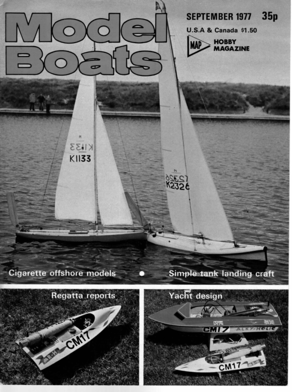
SEPTEMBER 1977 35p U.S.A & Canada $1.50 HOBBY MAGAZINE meee offshore” t design iienknipsitiie” x sttiiisedtben
MODEL BOATS 490 Part Two KOKANEE a “‘light’’ air Marblehead by Bill Van Dieren the boat for front support of winch platform. The back end of the winch platform is supported by a bolt arrangement. The bolt threads into a wooden block which is installed in the bottom of boat, and two nuts support the winch platform and a nut on top locks the platform in place. The bolt must be removed to take out the winch platform, (30 second job). Fabricate a tray for the receiver and a battery holder for the winch, and epoxy in place to suit. Check out your installation, make sure everything works properly and that all components required are installed before the deck is fitted. If everything is installed and works properly, you can take the equipment out and put on the deck. Use white glue or epoxy for fitting the wooden deck. Trim deck excess at the outside of the hull and around the two hatch openings. Note: Make sure you can install and dismantle all components through the hatch openings. Winch Winches of different kinds can be homemade, if one has some equipment, or can be purchased. 7 -_ 4 Ki ura Winches have two basic modes of operation: A Standard Winch is activated by a servo which throws a switch and starts the winch motor in a forward or reverse (8) us oz =i l»——— GENEROUS FILLET EI: direction, depending on the movement of the stick on the transmitter. The unit stops as soon as the stick on the transmitter is returned to neutral position. The sail is adjusted by visual means as required. i A Proportional Winch is activated by means of a modified servo and limit switches, which are arranged in a manner that the position of the stick on the transmitter 7 {| : OF RESIN &CHOPPED STRAND, ALL ROUND. GUNWALES (3)((0) eo matey BEAM (4) KING PLANK provides a certain sail setting, say for broad reaching. The position of the stick, (non-spring loaded type) varies between closed hauled and running positions. Visual corrections are still required, however; rounding a mark to a broad reach will allow the skipper to approximate the set of his sails. The type of winch used is a matter of personal preference. All of them work well if installed and operated properly. So, if you are on the market for a winch, talk to the skippers who own the different varieties available, after which time you may be able to select the one best suited for you and your boat. A relatively cheap proportional winch for home construction is described in the Model Boats Extra, now on sale. It is advisable to install the winch ona tin thick plywood board. The width and length will vary depending on the type of winch used and amount of radio equipment mounted on it. A slotted piece of tin plywood is installed in ! +——FIN(19) Wi Ne | DESCRIPTION 16 | FIN SUPPORT 17 | FIN CLAMPING BLOCKS 18 | 3/16″ ® BOLTS 19 | FIN FIG.5. MATERIAL 3/8″ THICK HARDWOOD 5/8″ THICK FIR BRASS ALLUMINIUM ALLOY 1/8″ THICK ARRANGEMENT FOR FIN ATTACHMENT.
491 Ballast September 1977 RESIN & CHOPPED STRAND The hull and deck of the boat are finished and your work so far sits nicely in the boat stand. The ballast should now be installed. Prepare wooden plug to the shape of the bulb and push into casting sand, and pour molten lead into the depression. The result is one ballast half, slightly concave on the mating side and a little rough on the outside. A full account of casting techniques appears in ‘‘Model Racing Yacht Construction”, by R. Griffin. Drill a in dia. hole in one half and then through the mating half. Countersink the holes on the outside to suit the bolt head and nut. Install a slotted hole in wide near the bottom of the fin. The length of the slotted hole should be as long as possible, as the weight will be used to bring the boat to proper trim along or parallel to the waterline. The gap between the two halves can be filled with plywood after the boat is trimmed, ora slot can be filed to suit the fin. Shape the ballast or clean up the surface and bolt to the fin. The boat will be very steady now and will start pressing into the foam of the stand. The mast step can now be installed. Be sure that the centrehole agrees with the mast position shown on the drawing, and the mast step must be placed on the centreline of the hull. Obtain this by stringing a line between the bow and stern and mark the deck at several locations and drawa line on the deck. Drill holes through deck and king plank with plywood below, and bolt mast step into place. Install the chain-plates by aligning as shown on the drawing and mark mounting holes on the deck and drill. Be sure there is enough room below for the nuts. The chain-plates may have to be moved away from the edge of the hull to suit. Fin installation The fin is going to be installed now, as shown in figure 5. The reason for this arrangement is to provide easy access to all bolted deck connections, and it also provides lots of room for the radio and winch installation. Cut a 4in wide slot in the bottom of the hull and make sure that the fin fits nicely. It is critical that the fin is parallel to the boat centreline. Make fin clamping blocks and assemble them to the fin with the bolts. Lower the fin into the slot and check that the fin hangs at 90° to the deck line. When all this is properly fitted, place a liberal amount of epoxy resin on the bottom of the blocks, press the assembly into the hole and check alignment. Install the fin supports after fin assembly is properly set. Provide heavy grp fillets all around and on the bottom of the hull as shown on the plan. Rudder assembly Drill a in diameter hole in hull as shown on the boat plan. This hole must be on the hull centreline. Make rudder post support and install rudder post, but leave an excess length of rudder post. Align rudder post properly with fin. Make rudder as follows; cut out one half as per boat drawings and put epoxy on three sides and stick on top of another piece of plywood. Trim rudder to shape after epoxy is set. Taper tube 33 by hammering and file a taper on the end of the tube. Open the top rudder halves and epoxy tube inside rudder. Fill remainder of holes with soft balsa wood and cover openings with a layer of epoxy. Solder item 34 and 35 into rudder stock, which should reach into the rudder. Place rudder post and support in hull, and insert rudder. Epoxy post firmly into position. Install braces 22 and make up the servo platform to suit. Blind nuts 28 should be epoxied in. Install the remainder of components as shown. NOTES: 1. Assembly may have to be installed opposite hand to suit your servo travel. Keep set screw on arm as shown on the drawing. N* | DESCRIPTION 20 21 22 23 24 a2 | 28 29 30 31 32 33 Ritq| | SUPPORT FOR RUDDER POST | RUDDER POST | RUDDER SUPPORT BRACE | SERVO SUPPORT | RUDDER SERVO 1 | ite 1 | PART OF RADIO RUBBER GROMMETS 4 6BA BOLTS 4 WASHERS 4 | 6BA NUTS | STEERING ARM +SETSCREW | LINKAGE ROD | ROD RETAINERS | RUDDER HALF | PART | | 34 | PART.2. 1 | BICYCLE SPOKE 2 | PLASTIC 2 | 116″PLYWOOD 1 (RUDDER STOCK RUDDER |)SERVO MOUNTING 4 1 35 | PART.3. FIG.6. MATERIAL &/or REMARKS 1 | 3/4* THICK FIR 1 | 1/8″ 1.0. BRASS TUBE 2 | 116″PLYWOOD | 1/8″0.0,3/32″1.D. BRASS 1 | 3/32°ODA/6″ID, —=— |_| 1/16″0.D. BRASS ROD ARRANGEMENT 2. Magnetize your screwdriver when you want to install or remove the bolt to mount the servo. This is easily done by sliding a small magnet over the shaft of the screwdriver. Below deck arrangement To complete the below deck work, one should have the following items ready for installation; (1) winch for sheeting, (2) radio receiver, servos, ni-cad batteries, on-off switch and charging plug and (3) batteries and battery holder for winch motor. WINCH CHARGING NI-CAD BATTERY BOARD WINCH BOARD ee GUIDE f= ciel Ig 1 RUDDER PUIG i HoT ; ASSEMBLY 7 | = ai | rece IVER WINCH BATTERY PACK WINCH ASSEMBLY BOLT-WINCH BOARD MOUNTING WINCH FORWARD- REVERSE SWITCH——— ON-OFF SWITCH SERVO FOR STANDARD WINCH OUTLINE OF MAIN HATCH WINCH BOARD EL WINCH BOARD GUIDE BLOCK. SUPPORT — 1/4″ PLY _3/16″@ BOLT -—& 3NUTS WOODEN ” RESIN & __lf_ CHOPPED AEC] STRANDS WINCH BOARD MOUNTING BOLT NOTE — Drill hole in block undersize and thread with bolt. FIG.7. GENERAL ARRANGEMENT NOTE-— Tray for winch battery pack is similar in construction. Size BELOW DECK and openings to suit equipment.
STHEAD FITTING t The mast, rigging and sails are the most important part of the boat. They are the power supply, and slight misalignments will ruin the performance of the boat. Review the Mast and Rigging — General Arrangement drawing, Figure 8, and start by making parts for the rigging. The jib sheet, main sheet, jib halyard and back-stay are all 50lb braided Dacron, and the four bowsies can be made. The jib sheet and main sheet go through a screw eye, the back-stay uses a hook to connect to a tang on deck and the jib halyard goes through the masthead fitting. The five tangs can be made, as well as the bottom pin for the mast, spreaders, hooks and masthead fitting, as per drawing, Figures 9 and 10. The mast can now be made from two pieces of aircraft spruce jin. x fin., glued together. Use white glue and as soon as pieces are pushed together, tape them with drafting tape. Keep checking for straightness. After the mast is taped up and excess glue wiped off, place the mast on a straight surface and tape down. Leave for 24 hours for the glue to dry. Remove tape and plane mast down as per Figure 9, The back side of the mast must be straight. Install spreader pin, masthead fitting, screw eye, jib luff cleat, main down-haul cleat, tube and pin on bottom of mast and screw-eye for kicking strap. Screw the tangs on for the upper shrouds. The tangs for the lower shrouds can be pushed on the spreader pin. The gooseneck can be fabricated as per the photograph, but others are detailed in the books Boat Modelling or Model Racing Yacht en Alternatively, commercial fittings could be used. ns tue \-—BACK STAY TANG EYE SCREW FOR JIB & JIB HOIST MAINSAIL CLEAT FOR JIB HOIST \ | UPPER SHROUD SPREADER JIB TANG ANTENNA (AERIAL) LOWER SHROUD BOWSIE FOR BACKSTAY MAIN BEAM JIB BOOM Ly ree AB ra Te ZL” FITTING EAP 4, Lz ee BEA FIG.8. Lage HATCH Ce JIB ZZ” s gr, le -2* PX Z ArT y EXIT GUIDE FORWARD HATCH COVER MAINSHEET & BOWSIE CHAINPLATE KICKING STRAP MAST STEP EXIT GUIDE “13 KICKING STRAP MAST & RIGGING —GENERAL ARRANGEMENT. (Part 3, including figures 9 and 10 next month). The saga of an ill-fated model ‘RUSTY’ by Raul Cardoso j you ever know of a boat that had been christened after her retirement? That was the case of Rusty. I needed a name to put on the top of this article and Rusty seemed quite adequate as you will soon understand. Those who have read my article on Toboggan (Model Boats, December, 1974), have been told how I started in this hobby of ours, but I did not confess at that time that Toboggan had been my second attempt into model boating. Actually, my first, ambitious and still unattained goal, was an exact scale model of the Long Beach tug, a beautiful design kitted in plastic by Revell. My dreamed-of model was a metre long tug, powered by a purpose designed slow running diesel, driving a genuine reversing pitch propeller through a gear box. sition for a beginner! A somewhat tough propo- Needless to say, my impatience in getting to the water made me postpone this pipe dream and return to reality, designing and building Toboggan around an old faithful Raul Cardoso’s home-made diesel, which was to prove a very frustrating engine. Opposite, 54in. Jerez cabin cruiser, used as test boat and subsequently renamed Rusty!
1977 R M Championship Witton, June 4/6 Report by Brian Bull ORTY-NINE boats were originally entered for this event but by the morning of Sunday, 4th June, five had dropped out for one reason or another. The original entry list included an 11-boat contingent from Basildon and three boats entered from France. Racing commenced at about 10.30 am after the OOD, Roger Cole, had welcomed all competitors and informed them of the course, laps, countdown times, etc, etc. The wind was none too strong and was blowing in from the north-west which is not the best direction for Witton Lakes. Apart from the occasions which involved the five ‘dropouts’, seven-boat racing was programmed. This gave each competitor eight races and a total of 56 races for the three days competition. Each competitor only met each other once during the event. Our gratitude goes to the Andrews family of Leicester who prepared and produced the racing schedule. Twenty-five races were completed during the Saturday and 17 penalties awarded. The leading positions at the end of the day’s sailing were: Ist 2nd 3rd 4th Eskimo TC3 Trapper E-Ecky Thump D. Hollom S. Kay O. Lee E. Nuttall S6pts SOpts 48pts 48pts Sunday morning saw a wind change together with an increase in the strength. Roger Cole also foxed everybody and altered the course to a sort of ‘figure eight’. It was also the day for accidents and collisions with masts tangling and Newport junior colliding with Newport senior, causing severe irreparable damage and subsequent withdrawal from the event. Eighteen races were completed on the Sunday and 29 penalties handed out, which reflects the number of incidents. On Monday morning, before continuing with the remainder of the schedule, the OOD ordered that two of the Photos by Vic Smeed previous day’s races would be re-run because of mast tangles. The leading positions after the re-runs were as follows: Ist 2nd 3rd 4th Sth Eskimo TC3 Kalamari Trapper E-Ecky Thump D. Hollom S. Kay B. Jackson O. Lee E. Nuttall 80pts 76pts 72pts 70pts 69pts The racing continued with the balance of the schedule which was completed by about 3.00 pm and after a rapid totalling up of the master score sheet it was realised that a sail off was going to be necessary for 6th place. The prizes were presented by MYA Chairman Norman Hatfield, who made a short speech expressing his thanks to the competitors for an enjoyable weekend and also to Birmingham club for hosting the event. At the end of the presentation, Derek Priestley representing the ‘north’ stepped forward and thanked the OOD, Roger Cole, for running a good race and having the courage to change decisions where necessary. In gratitude Derek produced a glass bottle containing a rather dubious looking liquid which Roger was fold to drink immediately. It turned out to be the beer “‘that reaches the parts other beers don’t!” Birmingham club wish to express their thanks to Fleetford MYC and Guildford MYC for the loan of equipment, the Andrews family for organising and producing the colourful schedule, Dave Knowles for the administrative graft, John Mountain for various pieces of lakeside equipment, either manufactured or loaned, the various club members and their families who came to the pondside and grafted — Taffy Williams, Harold Dovey, Bill Akers, Nigel Akers, Harry Scarrott and daughter, Vic Bellerson and Graham Webb’s daughters. Now that it’s all over it’s time to reflect and possibly reconsider the day-to-day race organisation in future radio championships. The main thing to come to the fore is that judges ought to be non-competing persons drawn from the local club or clubs and therefore be relatively impartial with their decisions. Heading depicts winner Dave Hollom (chequered cap) discus- sing finer points with Derek Priestley. Left, winning boat with shrouds hooked (centre) on second resail; only race he lost points on was the third resail. Mnementh is latest Chris Dick’s version of 247 (MM plan 1206) and features vertical fin. J. Mountain’s Verve, 2330, is pictured below the course diagram.
September 1977 Results 1 Eskimo (Ashanti) 2 Kalamari (Sea Horse) 3 TC3 (Sea Horse) 4 5 6 6 8 9 10 11 12 E-Ecky Thump (Sea Horse) Red Venom (Pterodactyl) Trapper (Trapper) Quicksilver (Trapper) Charisma II (Sweep) Mnementh (247) Verve (Verve) Pheidippides (Road Runner) Evalyn (Flipper) 13. Jayjo (S. Witty) 16 Green Devil (—) 14. 15 16 18 19 19 Lee O’ (Squiblet) Costabom (—) Southern Sea Horse (Sea Horse) X-Amount (—) Goldfinger (Trapper) Joanne (Sea Horse) D. Hollom B. Jackson S. Kay Leeds Ashton Bolton E. Nuttall Cleveland C. Eagle O. Lee P. Allen G. Thornhill C. Dicks J. Mountain Basildon Basildon Basildon Leicester Clapham Birmingham Mrs. E. Andrews E. Servella Leicester France 108 98 93 88 86 85 85 84 81 78 76 74 R. A. Clarke Leicester 73 T. Fuller New Forest 70 J. Torrance P. Metcalf G. May M. Holmes N. D. Hatfield S. Ward Basildon Bolton Tameside Basildon Basildon Bolton 72 71 70 66 64 64 21 22 23 23 23 23 27 28 29 30) 30 32 32 34 34 36 36 36 39 40 41 Alice Kaput (—) Don’t Be Long (Sea Horse) Boston Tiger (247) Reight Fantastic J. Richards Danson 58 P. Gilby D. Graham Cleethorpes Basildon 55 52 Legal Eagle (247) Stun (Squiblet) R. Potts D. Snelling Fleetwood 52 Ripple (—) Frantica (OD) Lulu I (~ B. Ashdown J. Curtis V. Cooney Minstel Il (—) Tantrum (Sula) Swish II (Dicks) Favandale (Flipper) Blueblood (Bloodaxe) Mr. Biscuit (Squiblet) Midnight Oil B. G. D. G. G. B. (Flipper) Zzub (Sweep) J. Perrin D. Broom (Ashanti) Rising Damp (Ashanti) Frolic (OD) (Mod. Bewitched) Windracer (—) D. Priestley Danson Basildon Woodley Basildon Woodley Woodley Woodley Basildon Birmingham Birmingham France Guildford 52 52 51 50 48 44 44 40 40 36 34 A) A. Oxlade Woodley 32 J. Seper Woodley M. Oxlade N. Curtis Burley A. Webb Knowles Sonchard Taylor Bardoe Basildon France Birmingham 32 29 22 17 … and the 1977 South African M Championships oe M. Colan WENTY-NINE marbleheads entered for this International event, including six boats from the UK. Walter Jones, sailing M-4-Sis, was defending his title won in 1975 when he beat Chris Dicks by two points. On this occasion the overseas entry, apart from the above two, also included Derek Priestley sailing Ashanti, Dave Latham with Reflection, Chris Dicks’ son Mark sailing Sir Jasper, a ‘247’, and Johnny Hyde sailing Chris Dicks’s new unnamed design. Racing started on Friday morning after the OOD (Officer of the Day) Mr Charles Cole, had held a briefing session. Unusually for Durban, the wind on the first day blew in from the sea, a light south-easterly, so top suits were the order of the day, and the racing involved tack and tack, and skippers were using their largest spinnakers. One of the first surprises of the day was Chris Dicks and Illusion losing the run unexpectedly to Les Wright, sailing Black Jack, from the Rand Model Yacht Club. Other points of interest were Johnny Hyde losing both ways to fellow clubmate Mark Dicks, and leading South African skipper Mike de Lange losing both ways to Chris Dicks. Walter Jones dropped runs to two sister ships sailed by junior members, Michael Coulon from Durban and Steven Wright from Johannesburg, and finished the day on 34 points, one point behind Chris Dicks and Dave Latham. Top South African scorer was Garth Thompson, sailing his own design, on 31 points. Imagine the surprise of the locals on the following day when the wind filled in exactly the same direction as the previous day. The top skippers continued to pile up the fives, but Walter Jones dropped a beat to Les Wright and a run to Mark Dicks. In the meantime Chris Dicks got top score, 38 out of a possible 40, dropping only a run to Garth Thompson. Top South African scorer for the day was Les Wright, who scored 27 points. The third day dawned miserable, cloudy with very little wind, and finally poured with rain. These conditions were a real dampener to the skippers and sailing became extremely difficult. The light winds kept changing direction, sometimes as much as 90 degrees, causing skippers much frustration. Top scorers of the day were Dave Latham with 38 points and Chris Dicks with 35. Top South African skipper was Keith Gerson with 30 points. The final day broke with a threat from the Met Office of the long awaited north-easterly blow, which is the Line-up of G.B. entrants, from left to right, John Hyde, Mark and Chris Dicks and Wally Jones. ideal wind for model yachting in Durban. Sure enough, at starting time, the north-easterly was beginning to strengthen and eventually settled to average 20 knots gusting to 25. Most skippers changed to working rigs or lower and we at last saw really high speed runs and good hard beating to windward. Five heats remained to be sailed. A feature of the final day was Chris Dicks sailing consistently and not losing any points, and Roy Curtis, lowly placed during the regatta, finishing only three points behind Chris on the day’s sailing. Walter Jones dropped two runs. Final scores were: first Chris Dicks with 133, second Dave Latham with 122, and third Wally Jones with 118. The Commodore of the Durban Model Yacht Club, Keith Gerson, managed to repeat his effort of 1975, by again winning the award for the first South African home by the narrow margin of two points from Jake Simons. The regatta concluded with a most enjoyable prize giving dinner dance which was enjoyed by all. The British skippers thoroughly enjoyed the regatta, the beautiful sunny weather, except for the Sunday, and the warm hospitality of their hosts. Chris Dicks in his speech at the prize giving, complimented the officials and all those con- cerned with the organisation and said he was sure they would all come back to Durban in 1979. The visit of the English skippers was of great value to the local model yachtsmen and whilst the visitors filled the first five places, the locals learnt a great deal which will stand them in good stead for the future. One such lesson was the correct use of the turning pole and the great advantage that this holds for a skipper when correctly used. (Results table overleaf.)
Model Boats 502 Pelee during the last few years, the new boats appearing in the A class fleet have demonstrated that the rule enables a wide variation in dimensions but nevertheless maintains competitive comparative performances. The yachts are probably more sensitive to the conditions of sailing and the type of water on which the competition is being held. We are likely to see a continuation of the trend towards specialisation of design in the so-called ‘lightweight’ bracket as these types combine easy handling with superior performance off the wind. This study is intended to examine the factors of design in a dozen different yachts to see if it is possible to rationalise the performances or alternatively to indicate potential advantages that one style of design may have over another. The following table lists the principal dimensions and characteristics of the chosen 12 designs. I have not named the designs as the owners may not wish this but rather have given them numbers in descending order of size. Those with the suffix (B) have fin and bulb type keels. limit allowed by rule. Graph No. 1 shows a hypothetical curve of sail area effectiveness which I have called ‘Driving Force’. Assuming that areas in excess of a measured 1600sq.ins. will have no measurably increased windward effectiveness, then all smaller areas can be expressed in equivalent areas as a percentage of 1600. The curve is almost certainly of exponential characteristic — it certainly is not linear — and a couple of ‘bench marks’ and a zero drive point establishes the curve as shown on the graph. Obviously for a measure of windward ability, the ratio given in the data column should be as high as possible. The figures are not too useful in assessing off the wind performance. (e) Displacement/sail area in sq.ft. is a ratio which perhaps is significant in making comparisons in off wind performance. In this mode of sailing, power/weight ratio is very important but the ratio in the data is not compensated for aspect ratio variation, in that low AR’s will tend to give higher drive off the wind, so in these figures the tows Analyses International ‘A’ Designs Design 1 2 3 4 5B 6B 7 8B 9 10 11 12 LWL Disp. (Ins) (lbs.) 60.00 78.2 60.00 63.0 58.00 67.7 58.50 68.4 57.00 45.4 57.00 45.0 56.00 57.8 56.00 39.0 55.00 59.5 54.00 40.0 54.00 54.5 52.00 36.0 S.A. sq.in. 1453 1291 1509 1463 1168 1157 1514 1085 1586 1263 1596 1334 Wetted Surface sq.in. 1099 1067 1030 1033 897 963 987 873 1048.9 847 996 740 SA| WS 1.32 1.21 1.46 1.41 1.30 1.20 1.53 1.24 1.51 1.49 1.60 1.80 DF{ Disp|SA WS 1.42 7.75 1.38 7.03 1.52 6.48 1.50 6.62 1.49 5.60 1.40 5.60 1.58 5.47 1.47 5.18 1.46 5.33 1.70 4.46 1.60 4.89 2.03 3.88 Prismatic oeff. 0.548 0.549 0.545 0.541 0.500 0.530 0.522 0.530 0.515 0.538 0.528 0.520 Note: (a) The Sail Area (SA) is in square inches and is as measured by rating rules. (b) Wetted Surface (WS) is in square inches and is the total surface area of the immersed yacht. Designs 6 and 8 have bulb keels which contribute 121 and 138 square inches of wetted surface but without providing useful lateral area. The volume of these bulbs tends to negate stability to a significant effect as shown in my previous article on stability, page 134, March ’76, Model Boats. (c) SA/WS – this ratio is interesting but does not take into account the effect of higher aspect ratio with reduced area as allowed by rule. (d) Driving Force (DF)/WS — this is an attempt to equate the relative driving effectiveness of the sails as area is reduced but aspect ratio increases. This of course assumes that designers will always go the maximum height INTERNATIONAL ‘A’ CLASS GRAPH .1. W DRIVING FORCE (% of 1600) 100 90 Kon SS a Seas 70 a 40 a —_ fe NG Sl 1600 1500 1400 1300 1200 1100 1000 900 MEASURED SAIL AREA IN Sq Ins N a 800 700 yachts with low sail areas, therefore high AR’s, will tend to be favourably represented in this respect. It is not believed that this factor is significant in terms of the overall precision of this study. (f) Prismatic Coefficient is the conventional coefficient used by naval architects to express an idea of hull form or displacement distribution and in all cases the canoe body of the yacht only has been used in the calculation. Generally speaking a higher coefficient indicates a higher potential speed in normal regions of speed-length ratio, say up to 1-3. Not being able to resist the temptation at this stage to select ‘ideal’ numbers in the table and having considerable knowledge of the performance of many of the yachts we can suggest the following for guidance: LWL Disp. Greater Below than 55.0 45.0 S.A. Above 1100 W.S. Below 1000 SA|WS DF|WS Disp|SA PC Above Above Below Above 1.3 1.5 5.0 The designs which most nearly meet these criteria happen to be Nos. 5 and 8. Design No. 5 has in fact been published in Model Boats recently and No. 8 is being built at present. However, the table does not take into con- sideration the two most important factors in yacht design, namely load water line and stability. Although an attempt will be made to relate these factors later, it is interesting to consider rather subjectively the possibilities of the following dimensions: LWL 60.00 Disp. 52.0 S.A. 1082 W.S. 880 SA/WS 1.23 DF|WS Disp|SA PC 1.45 6.92 0.55 There is no known A boat of these dimensions but these figures do make most of the premium that long waterline and stability provide. Before drawing any conclusions about this choice of dimension it is necessary to calculate the resistance of various hulls of differing dimensions and at various speeds. The calculations will not take into account subtle variations in hull form but will be adequate for general comparative purposes. In any case the choice of dimensions is the overriding criterion when designing a yacht. The methods of carrying out the calculations are based on the work described in the book The Sailing Yacht by Juan Bader and I do not therefore propose to go into the details of the calculations. The accuracy of the figures may be questioned but I assert that for comparative purposes they will serve our intentions. Two designs only are taken in detail, representing the more or less opposite ends of the equation and are Nos. 1
September 1977 503 and 8. Simple calculations show that other variants between these designs lie more or less on a straight line between them. To get figures on a like for like basis the speed ratio ote has been used as is normal in naval VL architecture, but one must not forget that in the actual racing result, it is the speed through the water that really counts and this is clearly a function of length, (below planing speeds). Resistance calculations summarised. (1) Speed —— eae Design 1 otal speed 1-12 knots=1-88 ft. per sec. Form resistance Surface resistance Graph No. 2 shows at aT. = 1-0 the relationship between form and surface resistance including (dotted) the surface resistance for laminar flow conditions. The arguments in these notes take figures assuming turbulent flow only, but it is certain that laminar flow should exist on our models at the speeds at which they sail. Due to the relatively small values involved and the considerable variation in laminar flow conditions, the calculations based on wholly turbulent flow are likely to be more meaningful for our comparative analysis, but keep in mind that the surface resistance figures may be high. Vy RESISTANCE IN POUNDS 0-141 Ibs 7 TOTALR , . Design 8 Actual speed 1:07 knots=1-80 ft. per sec. Form resistance 0-013 Ibs Surface resistance 0-092 5 3 Q) Speed —- = 1-0 Actual speed 2:23 knots = 3-75 ft. per sec. Form resistance Surface resistance 0-35 lbs 0-43 Design No.2 Actual speed 2:16 knots=3: ft. per sec. Form resistance 0-17 Ibs Surface resistance 0-33 Design No. 8 Actual speed 2:8 knots=4-72 ft. per sec. Form resistance 0-65 Ibs Suriace resistance 0-51 1-16 Ibs Speed differential is 9 ft. per minute. . MINAR . —-— b= La” FORM ral 60″LW.L. , 40 it needs to be shown what difference exists if everything Now let us examine the data we have and relate lengths, sail areas and resistances to these.yachts when travelling at the same actual speed rather than the Bee (a) Firstly take design 8 at a = 1:3. We have a total GRAPH.3. Cae IN POUNDS RESISTANCE a4 ae FORM TOTAL R 2a 4 = 6O”LW.L@ FORM RESISTANCE ge 56″LWL. pe 0-18 0-2 7 =10 en) 0 7 ———— 32 40 sO a 0-1 = 0-50 vt a as — TOTAL R oe GRAPH.4. FORM RESISTANCE A 7″= 10 ok 0-22 1 80 70 (continued on page 513) fs i (\bs) DISPLACEMENT Graph No. 3. This shows the total resistance at the three selected relative speeds with varying displacements. Graph No.4 Because graphs 2 and 3 show the change in resistance due to speed and displacement as variables 0:26 0-6 60 50 resistance of 1-16lbs. The sail area available in equivalent 57 Vr 130 oi: ——_ es or 1-4 6O”LWL. A Se ee ie ments. 1:66 lbs pee SURFACE R in resistance due to length alone is indicated and what there is has been ignored in the analysis as being well within the limits of approximation taken generally in these argu- Design No.1 Actual speed 2:9 knots =4-87 ft. per sec. Form resistance .. 0:99 Ibs Surface resistance 0-67 ist R LAMINAR FLOW — and at a speed of at = 1-0. Remarkably little difference —— = 1:30 _WRESISTANCE IN POUNDS a Graph 4 shows the total resistance of a 60in. LWL hull compared with a 56in. LWL hull of similar wetted surface Speed differential of 7-2 ft. per minute. 1:6 = equates except LWL. 0-50 Ibs Speed we pl ae SURFACE R °39 -78 lbs (3) cea | —_— —— — Speed differential is 4-8 ft. per min. ob , aa _——_| pS ia TOTAL WITH 0-105 Ibs Design No. | GRAPH.2. RESISTANCE IN POUNDS at SPEED ¥ = 1:0 0-021 Ibs 0-120 Ibs 0-06 — 60 DISPLACEMENT ({bs) 0 0-02 32 40 50 60 DISPLACEMENT —POUNDS 70 80
Model Boats 508 the hull in two parts. The first part is up to quarter deck level (the bulges should be added afterwards), and the second part, including the casemates minus guns, added afterwards. The best method is to cut out the deck and add the casemates to the underside. These can be small wood dowels or short lengths of plastic tubes very carefully cut to the correct height. The hull between the casemates should be filled in with strips of thin wood or plastic card. The space behind the casemates can be filled with balsa board of the requisite thickness. Although you may wish to drill the holes for the guns in the casemates at this time, the guns themselves should not be fitted until the model is nearly finished as they will be very much in the in place with contact glue. It may be necessary to give them a final rub down with very fine sandpaper after they are on the model. Later the square gash chutes and other discharges can be added to the bulge during the final stages of construction. Once the hull is complete the rest of the model should be straightforward. Particulars of HMS Royal Oak were as follows: Built: Devonport Dockyard, Jan 1914 — May Displacement: 31,200 tons (deep load) Machinery: Armament: Readers Write… 15th CENTURY RESEARCH Dear Sir, Through the columns of your very able magazine may I make inquiries from your readers about a fascinating era in world history; namely, the great age of exploration of the 15th century. It has already been said that with the exception of Noah’s Ark, Columbus’ Santa Maria must surely be the most well-known ship in the world. Certainly there is scarcely a kit manufacturer today that does not include a copy of her. However, the great age of discovery goes back as early as 1422 to the Portuguese under the guidance and influence of Prince Henry the Navigator. His ships were mostly caravels, an ocean-going development of early single-masted Mediterranean fishing vessels. These ships with their very characteristic 3-cornered sail, known as a ‘lateen’ sail, carried out many astonishing voyages. Not since the Vikings had little ships been so far away from home shores and one can imagine the great psychological hazards that first had to be overcome. These expeditions reached their peak in 1498 with the epic voyage of Vasco da Gama, the first man to reach India by sea round Africa. However, Da Gama’s ship was not a caravel, but was specially built for the expedition on the advice of Bartolomeu Dias, Da Gama’s predecessor. Dias recommended square rigged vessels, of broad beam and small stores draughts which could carry more than the caravels. Moreover, the vessels should have higher freeboards, the better to withstand the gales of the Southern Atlantic. One wonders if his harrowing experience rounding the Carbo Tormentosa — the Cape of Storms, as he called it, had anything to do with this? Vasco Da Gama’s flagship, the Sao Gabriel, was about 200 tons displacement, square rigged on two masts with a lateen sail on the mizzen. We know little else about her. She was also probably a carrack, ie, the hull form rounded aft towards the rudder, which according to many authorities today was the hull shape of the Santa Maria, although I don’t think there is a kit out, including Billings, that show her as such. Da Gama’s expedition was all that was expected of it and more! It opened up the other half of the globe, and the spice route to the East for the Europeans with all its devastating social/political consequences. The voyage took 2-years. In that time Da Gama sailed 24,000 nautical miles. At one stage the Portuguese were out of sight of land for over 3-months (96 days). Columbus’ round trip away from Spain was some 7- months all-in-all. 40,000 SHP=22 knots 8 — 15 inch; 12 — 6 inch; 8 — 4 inch AA; 16 — 2 pdrs; 8 machine guns; 4 — 21 inch Er way. Once the hull is complete the bulges can be added. These should be made from wood or plastic card and secured 1916 Complement: About 1100 Next month: Coronel and the Falklands Part I. I would be grateful if I could hear from any of your readers who have researched ships of this era, and if, indeed, any of them have gone as far as to build models of the same? I refer in particular to Da Gama’s, Sao Gabriel? However, I would also be pleased to hear from anyone who has tackled a caravel — a remarkable little ship if ever there was one. With Africa increasingly in the news, and with the great interest now being shown in the Continent as a whole — its history and its peoples — it’s time now that historians and modellers alike got down to reconstructing what was truly a great age for both men and sail. G. Wilson 11, Oberon Way, Meadowridge, Cape Town NO ‘LUFFING’ MATTER Dear Sir, I cannot entirely agree with the tone of your report of the 1977 Nylet Trophy, in last month’s issue. This said that I took a tough line and issued penalty points in most races. AsOOD if I, or any of the Committee for that race, see a collision or a touch, then under the rules one boat must have a penalty. I, therefore, took the only line. Your reporter also deprecated the fact that there was lots of luffing in the sail off for first place and had there been a third boat in this race it would undoubtedly have won; something I would agree with. Totally different strategy must be employed in a match race and, obviously, if a boat attacks one’s weather on a run he must expect to get luffed, as otherwise he is bound to sail through by taking the leeward boat’s wind. To pass a boat on the run in a match race one must either attempt to pass several boats’ lengths to leeward or automatically get involved in a luffing match. The touch that ended the race was, in fact, caused, as I saw it, by Noel Hutchins bearing away into Knut, possibly into the mistaken impression that he would get under Knut’s stern and gain an overlap for the next mark. John W. O. Cleave H.M.S. SANDPIPER Dear Sir, I was very interested in Mr. R. B. Down’s letter in last month’s issue, and to hear that he has had difficulty in finding photographs of HTMMS Sandpiper. There is a book ‘The Royal Navy and Sino-Japanese Incident 1937-41’ by Martin Brise and published by Ian Allan, which has excellent photos of both Sandpiper and Falcon, showing quite a lot of detail. As regards triple rudders, and propellers in tunnels, my own 38in. model of an Insect Class gunboat, runs and steers quite well in a few inches of water. I carried the exterior shaft well down the tunnel, to get a good ‘flow’ and increased the length and depth of a i rudders under water, slightly over scale. Incidentally, my 1953 Janes shows a photo of the Chinese Ying Hao ex Sandpiper, a port side view showing her motor sampan swung outboard. It was obviously taken for Thornycroft Limited when Sandpiper was on trials. R. E. Gardiner STEAM AGAIN Dear Sir, I just spent an entire afternoon going through my collection of Model Boats which date back to 1972, when I first discovered your one and only magazine covering model boats. I was looking for articles that had to do with live steam. After the search I was quite disappointed that there were not many, and those that were, except for a few, had little to offer insofar as any construction was concerned; that is, on boilers, engines and heating techniques. What prompts me to write is that there are a growing number of modellers, especially in this country, that are becoming more and more interested in steam; primarily I think because this kind of power is noiseless, working machinery that is exciting to watch even by the spectator and beyond that it has a great deal of charm and a true execution of realism in miniature. I am sorry to say that after scanning through several years of Model Boats, gas powered and fast electrics dominate each issue, except for a generous allowance for sailing models which saves the day for those not interested in gas and battery powered boats. Well, what would I like to see published in the area of steam? To begin with, there is no end to the kind of information steam enthusiasts are hungry for, and to mention a few would be boilers, materials for construction: brass or copper? If brass, what specific kind of brass, gauge, size and evaporation rates ?, hydraulic boiler testing, engines that can be built without a lathe, being of single cylinder double acting with simple slide valves and two cylinder types, simpler poppet valve and oscillating engines. What is lacking most is means of firing boilers. We have spirit burners, gas torches, gas bottles and a very popular self vaporizing burner. This latter has had the least attention insofar as any construction data, especially as they are safe and efficient. I am making an attempt at building one, but without much to go on, I am hoping for a degree of success. What I have asked to be considered for publication is but a drop of information which steam enthusiasts are looking for, and adding to the above there is the problem of drive shafts, propeller sizes for various size power plants and hull plans for exposed machinery — why hide the elegance of a steam power plant? Well, there may be some grammatical and spelling errors in what I have just written, but I am sure many readers could well share in my enthusiasm. Florida T. Nadeje Look out for a series on marine steam starting soon in MB. Ed.
513 The flexible shaft is protected by a Zin. diameter brass tube, supported in the hull in the normal manner at engine end and by a cast bracket at the propeller end. Whilst providing the very necessary protection, this brass tube has to be bent to the desired angle, and does remove one of the advantages of a flexible drive, i.e., being able to easily alter the angle when initially trimming out the model. The most beneficial effects are likely to be seen with multi-rail or straked hulls, where shaft angle and propeller position have always been much more critical than with a semi or deep-vee design. The RM flexible drive system, including a full page of installation instructions, costs £8.95, Model Mouldings, Camberley, have produced a grp based compound specifically for joining wood or metal to fibreglass. Called Eze-build, it will be found extremely useful for (continued from page 503) driving force by my previous statement is 1280sq.ins. Therefore we have a SA/Ib (resistance) ratio of 1103. Now take design 1 travelling at the same actual speed as 8 above and we have a total resistance of 1:50lbs. The sail area available in equivalent driving force is 1560. Therefore we have a SA/Ib (resistance) ratio of 1040. In other words the heavy boat has less sail area available to overcome the resistance than the light boat and, therefore, should be slower to windward in fresh wind conditions. However, my previous studies on stability calculations show that the heavy boat is more stable and therefore more able to carry sail than the light boat and so will not suffer as much as these figures may indicate. In fact the difference in angle of heel between the two designs will be about 6° and in terms of effective sail area this gives the heavy boat about 6-5% advantage in driving force. This factor added to the equation brings the heavy boat’s area from 1560 to 1661sq.in. and makes the SA/Ib (resistance) ratio 1107. This has now put the heavy boat on a slight advantage to the light boat. This result equates quite well with actual practice to windward but now let us see what happens downwind. With the two boats travelling at the same speed as before the resistances are again 1-16 and 1-Slbs as I have ignored induced drag on the windward figures but the effective sail areas change and are more nearly the true measured areas. Let us put however a 2°% penalty on the light boat due to the higher aspect ratio of the sail plan and we then have: Design 8 Resistance 1-16 sail area 1085 —2°% = 1063 Therefore SA/Ib (resistance) = 916-4 Design 1 Resistance 1-5 sail area 1453 Therefore SA/Ib (resistance) = 968-6 So again we show that the heavier boat has an advantage in driving force available and should be faster than the lightweights. However, at this speed the resistance curve of the heavy boat will be rising very sharply and the light boat will move more easily into a semi-planing or fullplaning condition. Thus the light boat can always leave the heavy boat behind when marginal planing conditions as above prevail. The argument now needs to be repeated for design 8 sailing at ne = 0-5 and therefore establish whether there is a trend favouring either boat in light/medium winds. Design 8 at 5 ee ime 0-5 has a resistance of 0-105lbs and the equivalent sail area is again 1280. Therefore we have a SA/|b (resistance) ratio of 12190. Design 1 at same actual speed has resistance of 0-14 Ibs September 1977 installation of engine mounts, bulkheads, prop-shafts, etc. When mixed with a few drops of the hardener supplied, setting takes a few minutes at room temperature, with full strength developing within a few hours. A 400 gram supply costs £1.48 from most model shops. Distributed by Racing Models. The alloy mast extrusion is from Nylet Ltd. and is suitable for all classes of yacht, but is normally supplied as an 87in. length. Weight is 300gms. or 3.4gms. per inch, which is probably as light as is possible, whilst still retaining an adequate safety margin. The wall thickness is 0.8mm (32 thou), and section shape can be seen in the photograph. Diameter, athwartship, is 4in. Our sample was very smooth and clean and the mast is silver anodised for corrosion protection. Retail price (inc. VAT) is £6.70 a mast. and sail area equivalent to 1560sq.ins. Therefore we have a SA/|b (resistance) ratio of 11142°8. This shows an advantage to the light boat, but look at the stability curves and we see that the effective sail area is improved in the case of the heavy boat by 1-8 %, giving a new equivalent total of 1560+-1-8 °%=1588sq.ins. There- fore the SA/Ib (resistance) ratio is now 11343. This still leaves us with a slight advantage in the lightweight boat to windward in light air —a perhaps surprising but not incredible conclusion. Downwind we have: Design 8 resistance 0-105lbs sail area 1063 Therefore SA/Ib (resistance) =10123°8 Design 1 resistance 0-14 sail area 1453 Therefore SA/Ib (resistance)= 10378 Therefore the heavy boat is showing a very slight advantage downwind in light airs. Conclusions Bearing in mind the approximate nature of these calculations, it is demonstrated that the difference in performance between the light and heavy displacement yachts are remarkably small up to speeds Pee 1:3. Above these speeds the lighter boats must have considerable advantage and in models these speeds are easily exceeded on any point of sailing other than a dead beat. The fact that the heavy boat has the slight edge in all conditions below a 1-3, except light air to windward, is interesting and demonstrates the relative advantage of the smaller but higher aspect ratio sail plan of the lighter boat. It is indeed fortunate that the A rule carries a sail area penalty for light displacement as without it the heavy boats would not be competitive under any circumstances. In fact I am sure the original intention of the penalty was to render the light boats non competitive and keep the class stabilised within discreet limits and thus competitive. With this analysis showing such slight differences between the types of boat covering a wide range of displacements it is therefore certain that variations in design shapes and wetted surface consideration are of prime importance in A class yacht design as well as choice of principal dimensions. In fact within this class they may be of more importance, which is rather unusual in naval architecture. It all goes to show what a superb rule we have and it must not be tampered with, or else the complex relationship between the various factors would be upset and a few years of unbalanced development could lead to the death of the class as it is now recognised. For interest I comment on design number 12 as this is a special case in that it is specifically intended to be competitive only in winds below 10 mph. I think the analysis justifies the choice of those dimensions.
Model Boats 522 ‘LOG BOOK’ Latest yachting news from our M.Y.A. Correspondent VISITOR at the MYA stand at the last ME Exhi- bition was Giancarlo Tomarelli who was seeking information on R/C yachting for a very active new group in the Rome area. Shortage of designs and accessories not to mention information was making life hard; the club had made a start with Genies (Sr Tomarelli himself has made six!) but wanted grp hulls, etc to spread their interests. Any kind of advice etc would be welcomed. The address is G. Tomarelli, Vicolo della Serpe 81, 00149 Roma, Italy. Nottingham MYPBC suffered a break-in at their clubhouse, in the grounds of the local university, in early June. Two Jones vanes, a Fisher vane, and a varnished cedar-planked Star C hull with Jones deck fittings were among items stolen. Eric Berthier, 3 Glade Avenue, Wollaton Road, Nottingham, would appreciate any sightings. The World Open Championships for RM and RIOR classes will be run 7th-21st August 1978 at Durban, South Africa. Entries (R5.00 per boat) close on 30th November 1977 and are open to members of clubs and national associations affiliated to the IMYRU. First event will be the Canada Cup for R10Rs, which will be completed before starting the RM event for the South Africa Cup. Durban Lake is about 200x50m, about $m average depth, and August winds are usually moderate to fresh, up to 15-20k. No licences are needed, but three frequencies minimum are stipulated. The MYA of SA hope to offer sponsorship for the air fare of one nominated competitor per country. Accommodation can be arranged, hotels, flats etc. Entry forms are available from MYA Sec R. Gardner, 6 Rowner Close, Rowner, Gosport, Hants and further particulars can be obtained direct from Keith Gerson, 532 Frere Road, Durban 4001, South Africa. An international regatta under Naviga rules, for F5X, F5M and F10 is being held on 17—18th September at Duisburg. Looks as though entry intention had to be advised by 15th August to W. Quurk, Allgauerstr 8, 4100 Duisburg 28, W. Germany, but even so anyone over there at that time may like to see what’s going on. It seems that they’I1 be sailing 6-boat races and a protest requires a Dm20 deposit; the lake appears to be at Freibad 6. Four new MYA clubs were elected to membership at the last Council meeting; Killingworth Water Sports Association (L. J. van Talligan, 31 Norham Road, Whitley Bay, Tyne & Wear), Peterborough RCS (C. J. Foster, 11 Alderlands Close, Crowland, Peterborough PO6 OBS), Port Talbot MBC (S. E. Johnson, 24 Oaklands Road, Bridgend, Mid Glam CF31 4SN) and Ramsley RCYC (B. Axon, 39 Sherwood Road, Thornloy Park, Denton, Manchester). Biggest constitutional change recommended by the sub-committee which has been looking into updating the MYA Constitution is that there should be two District Councillors per District rather than one, one of whom should be au fait with R/C matters; this would dispense with the need for a separate R/C Committee. A number of alternative methods of adjusting club voting powers have been suggested — see the MYA circular which club secretaries have received. Has your club paid its 1977 affiliation fee, by the way? Suggested rules for conduct of R/C Team Racing events were drawn up by the R/C Committee, as instructed at the AGM, and will, it is hoped, be tried out at an experimental level. Minutes of the May R/C Committee meeting list these, but a later suggestion should be noted. Scoring should be as for six-boat races, but with three-boat teams sailing this could result in a lot of tied scores. An additional point awarded to the winner of each heat will help to produce a clear-cut winning team. On radio yachting, a reminder that while a boat may have technically scored when its bow crosses the line, penalties can still be incurred until the whole boat has passed the line. The obvious example is if the stern touches a mark; the boat must still circle the mark and if another boat crosses in the meantime, well, too bad! Some dissatisfaction is currently being expressed at the practice of all skippers taking turns on the judging panel during R/C races. Fine in principle, but inexperienced skippers do not necessarily know the rules well enough, which has led to occasional problems with protests that shouldn’t be upheld and vice versa. Experienced judges are really needed, especially at top level meetings, though the difficulties are appreciated. Perhaps if a proposition coming up at the next AGM is passed — that rules should only be changed or amended once every four years, as in full size — there will be a slight improvement, but it is a situation that needs airing. By the time these jottings appear, Fleetwood A Class will have come and gone. Interest can confidently be predicted in a 30lb boat which will be sailing there; a 22lb one has been mooted but not yet built. Where, as they say, will it all end? The Secretary Writes… M.P.B.A. International Secretary, Jim King on a Swedish regatta, scale topics and steam ie my closing words last month I expressed the hope that Jim Fagan would provide some news of the Swedish Multi Grand Prix, and like a good trouper he telephoned as soon as he arrived back in the UK. Un-


