- Panache Our Christmas Free Plan features this attractive 30in semi-scale ocean racer for vane or radio control Designed by Vic Smeed

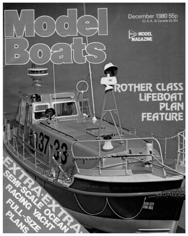
December 1980 55p (U.S.A. & Canada $2.50) “a> MODEL MAGAZINE SS CLAAT R EBO OT| HELiF PLAN FEATORE
Hand rails and cockpit turn a functional racing model into an attractive semi-scale ocean racing yacht. Note rudder linkage emerges through forward cockpit wail. Our Christmas Free Plan features this attractive 30in semi-scale ocean racer for vane or radio control Designed by Vic Smeed Design As a supporter of the idea that a smallish yacht of scale appearance could attract new members to the Model Yachting Association, if the Association adopted and promoted such a concept, it seems reasonable to produce such a design to attempt to gauge the degree of interest. Ideally, a yacht for such a purpose should be based on a round bilge hull lending itself to vacuum-forming, but for wood construction, experience shows that a chine form is likely to prove more popular as being less expensive and quicker as well as requiring only quite easily available materials and no unusual skills. A chine boat, however, does not have be flat and angular, as can be seen. Most newcomers to sail these days are attracted by the idea of radio control, so the capability of accepting radio is an essential component in the design. To use a normal servo for sail control Even if a public library does not have yachting periodicals, it is likely to have books on ocean racing, usually well illustrated. Edward Heath’s Sai/ing is a good example, with lots of good pictures showing deck layouts etc, mostly for the four Morning Cloud designs but including other boats. There are certain basic differences between racers of this type and a practical model, notably the absence of a genoa and the pivoting of the jib boom, but as a source of ideas for deck detail, photographs of such boats are extremely useful. The final design to emerge owesa little to the fourth Morning Cloud in deck arrangement but is of hard chine form with a ‘typical’ profile and a planform perhaps not quite so exaggerated as some drum-winch at 2.90z and the Sanwa lever type at 50z; using the modern full size craft. Something of a rule-of-thumb application of conic projection enables the ends to be curved in section, adding considerably to appearance without making construction any more difficult; it will be found that if the bottom and side panels are first pinned to the ‘flat’ section (B4), the bow and stern curves will fall naturally into place without steaming or struggling. latter suggests an installation of say, 120z total, perhaps a shade Construction more if highish capacity nicads are used in place of the dry cells of Construction starts with tracing and cutting out the bulkheads (or frames) and the backbone, plus T1 and the fin, and by preparing a requires either a very small boat or an unconventional rig such as the Mickey Finn or Wing Ray but sail winches can be heavy and costly. The two lightest and least expensive are the Whirlwind the inexpensive GC2-2B outfit. If we allow 50% ballast weight, 20% radio and 30% for the hull and rig etc, we come up with around 5lb total displacement, and this is quite a feasible weight for a 30in hull. With radio, it is nice to keep the deck as dry as possible, indicating that reasonable freeboard should be an aim, so with a few quick calculations, it is possible to arrive at a rough idea of what the boat’s dimensions could be and sketch out something to fit. Next is finding a full size design or class which can marry to the simple building jig. This last can be any dry, flat piece of timber along the centre of which are drawn two straight parallel lines 3mm apart. It is worth drawing accurate cross-lines at the bulkhead positions. Cut a number of small blocks, say 3/8in square and an inch long, and glue these in pairs either side of the parallel lines between the bulkhead positions. The top of the backbone will slip in between these to be held straight and upright; a small touch of glue can be used to hold it firmly, although this did not prove dimensions and sketch to achieve the sort of scale-like appearance sought, enabling a sport sailor to add all the bits and pieces of gear necessary with the prototype. Notice that 3mm gaboon ply is specified. This is a very light and if he so desires, but clean enough to make it a satisfactory functional model. The new breed of ocean racers, with virtually flush decks and tiny cockpits, seem a better choice than a cruising yacht with a large coach-house etc, especially as they mostly follow the fin and skeg layout. It is necessary to increase the size and particularly, depth of fin to make an efficient sailing model but this of course, will not be noticeable with the boat afloat. quite soft reddish ply much used for panelled doors and not usually very difficult to find. There is, however, a common 4mm gaboon-faced ply with a harder and much heavier centre leaf 748 which should only be used if the 3mm type (which seems only half the weight) cannot be found, but if this is used, it would be worth fretting out the centres of the bulkheads to save some of the weight. Model Boats
Top, left to right, various stages in framing with particular emphasis on transom and fin area. Above, joining skins at bow. Right, fitting deck, cockpit and radio compartment skins. Early decisions are called for if radio is to be used, since some idea of the installation is required. At a late stage it was decided to use the Sanwa winch below deck, which meant sawing out a slot for arm-clearance through a bulkhead after the hull had been skinned. Although below-deck mounting is more of a fiddle, it would look strange to have a relatively large arm swinging over a scale-type deck, and the idea of dropping the 5oz servo an inch or so lower was attractive from a stability viewpoint. If the same sort of mounting is to be followed, the slot can be pre-fretted, leaving only a small length in the centre to be sawn after assembly. If a larger hatch is thought desirable, slots for the deck bearers can also be planned and cut before assembly. The bulkheads are slid in place in the backbone, using Uhu or Durofix, or even PVA glue or balsa cement (the soft ply allows cement to key quite well) and T1 slipped in place. Check that everything is aligned squarely and leave to dry before adding the 3/16in sq spruce inwales and the 3/16in x 3/8in balsa chine strin- gers. The strips should be attached in pairs to avoid distorting the frame and need only be cut to the correct angle to butt to the backbone at the bow, as there is adequate area to glue. Cement the two T3 pieces of 1/4in scrap balsa to the bottom of T1 and carve and sand to a fair curve matching that of B7. Now glue in the doubler pieces on one side, allow to dry, then cut away the centre backbone to receive the fin. If no radio is to be fitted, cut a skeg and fit this in a similar manner. Add the second doublers and leave to dry. Next sand down the chine stringers, the doublers, and the backbone, to form a fair seating for the bottom panels. Templates are included for bottom and side panels, and you may wish to trace these onto stiff brown paper or thin card, to check and finalise their shapes before cutting an expensive piece of ply. In fact the patterns given allow a fair margin for trimming, but a certain amount of work can be saved by making the centre butt joining edge, over the backbone, a nice fit before it is actually glued in place. Note that there has to be a slightly curved cut-out to ensure a snug fit against the fin. The only other fairly critical bit is the first four or five inches of the chine joint at the bow, which should be straight and correctly positioned on the chine strip; it is possible, however, to cut this line with a sharp blade and a steel rule after the skin is in place, provided it is done gently and care- fully. Skinning Use 1/32 in (.8mm) ply for the skins. This is sometimes referred to December 1980 loosely as 1mm ply, but there is quite a difference between .8mm and 1mm in flexibility: Hard steel dressmakers pins pushed in with pliers should be used to hold the centre edges in close contact with the frame; clothes pegs or bulldog clips can be used along the chine edges. Leave to dry, then carefully trim away the surplus exchanging the chine and transom, remembering that with the latter, an acute angle will be sanded in, so do not trim absolutely flush. The hull can now be lifted off the board. The only tricky bit with the side panels is again atthe bow. First sand the inwale and chine (and bottom panel edge) to a fair seating, noting the special treatment at the bow end of the chine, then check that the stern angle of the cut panel is correct when itis laidin place to cover all the other edges adequately. Pin in place and carefully trim the chine edge of the panel at the bow to butt exactly to the square edge left on the first few inches of the bottom panel. The photographs should make the joint method clear. When satisfied, glue and pin in place, ignoring for the moment the transom overhang. When dry, trim top and bottom edges and repeat for the other side. Now mark the top and bottom edges at the transom position, pencil between the marks with a flexible guide (a straight piece of ply or card) and carefully trim to the line. At this time the ply is unsupported and curved, so several gentle strokes with a sharp blade are needed rather than heavy pressure. Cement in the iin balsa T2 pieces and carve a couple of scrap lengths to fit snugly inside the ends of the side panels. When dry, sand the whole transom area to blend in and form a smooth seat for the ply transom, pin a piece of .8mm ply in place (outside grain vertical for an easy curve) and draw round to mark the shape. Remove, cut out, and glue and pin back in place, trimming away surplus when dry. Stand It is as well to make a stand at this stage, the simplest being two ply shapes to fit the hull fore and aft of the fin, glued and screwed to a piece of inch thick timber as a base. The contacting edges can be covered with rubber or plastic by slitting lengths of tube and contact cementing over the ply edges, or by using draught proofing strip, though this may stick to a wet hull unless the hull surface is kept waxed. Fin Glue pieces F1 each side of the fin, then cut panels from clean lead flashing as indicated on the plan, to a weight of about 23lb, which 749
Nylet sails were used on the prototype. Details re availability in text. Radio hatch sealed down with tape. two or three undercoats well rubbed down and a finish coat. Before finishing, a quick flotation check can be made with the radio aboard and three orfour ounces on deck at the mast position, to see that all is well. Mark waterline etc, and use a glass finish on the hull but eggshell on the deck, or glue fine wet and dry anti-slip patches on allowsa little for filing to section. If no radio is to be fitted, the lead can be increased to say, 33lb, which is why the F1 pieces may prove a little too wide for the lighter lead. Flatten the lead sheets between two pieces of wood in a vice, or by tapping with a hammer, lightly key the surfaces with glasspaper (removing any patina ifthe lead is not bright) and epoxy to the fin. When dry, file to shape and fill any flaws with Plastic Padding or lsopon etc. Cut and cement balsa sheet in the spaces between the F1 pieces and the hull bottom, and when dry, sand to shape. At this point drill for the rudder tube and epoxy it in place and make up the rudder. Note that the non-radio rudder tube should extend to deck level. Internal Finishing Give the interior of the hull two thorough coats of polyurethane varnish and check on the radio installation, fitting any necessary platforms etc on which to mount the various items. The varnished surfaces of the ply will allow the use of adhesive pads for mounting the servos but every builder has his own preferences. If a Sanwa winch is to be used, fit wire hooks to secure the ends of the sheeting lines; the forward one will be out of sight, but the line can be attached without too much difficulty by fishing with a slip knotted loop on a bent wire fork. Vane Gear If a vane gear is desired, the simplest way is to bend a brass or s/s strip to make an outrigger bolted to the transom (long bolts right through B7 would be advisable) or a flat V-shaped outrigger cut or fabricated could be bolted to the deck. The outrigger should carry a bush for the shaft of a rotating gearwheel and a pivot on which a second gearwheel can rotate, meshing with the first. This first or inner gear needs an arm athwartship, linked by a push-rod to an athwartship tiller on the rudder shaft. The second, outer gear requires a vane feather mounted on it (see Plans Handbook No 2) and must be capable of being lifted up it’s pivot, rotated, and dropped back into mesh. Make the vane arm long enough to have some leverage on the gear, but not so long as to allow the vane feather to foul the rear pulpit (or ‘pushpit’). About 8in tall and 14in wide should be reasonable for the vane feather, made from 1/16in balsa and polyurethane varnished. Deck When satisfied that everything is in order inside the hull, cut and fit the deck. Trim and sand, then decide whether to fit a 1/16in sq footstrip before or after painting, or not at all. Make up the cockpit, either as a box slid into place or by first fitting the floor, then sliding in the sides and ends. Note that the radio rudder tube pokes up through the floor; hold the floor against the top of the tube, correctly aligned, and slide a drill up the tube and give it a twirl to mark the spot for the clearance hole. Since the crew sit on the cockpit edge, it should either be flush or, if projecting, a flat 1/8in wide balsa pad should be cemented round the edge and sanded to a curve. Finishing and Detailing The hull and deck can now be varnished/painted in the usual way, 750 the deck and paint these. Include the rudder in the painting stages, also the radio hatch, which can be laminated ply or a framed ‘box’ hatch. The prototype model uses an overlapping square of polystyrene card held down with a narrow strip of plastic insulation tape, which is practical and efficient if not altogether scale-like. Deck details are a matter of taste, but the safety rails make an enormous difference to appearance. The various scale-type hatches can be drawn on; the ventilators are not difficult since suitable commercial ones are available. The midship ones are usually unshipped and the ducts plugged during racing. Note the racing type wheel and the coffee-grinder winch, also the number of winch drums surrounding the cockpit front. While racing, the deck is covered with lines laid out in an orderly fashion and a spinnaker boom would be secured inside the rails on one side. Winch handles clipped to the cockpit sides, double doors beneath the sliding hatch, navigation lights, even crew members (5 — 6in tall) all add to the bits and pieces a scale enthusiast may care to add. Mast and Rigging Because of the problem many people seem to have in acquiring aluminium tube, a dowel mast has been shown. This should be straight and straight-grained; it needs a screw in the heel, cut off to form a mast peg, an eye near the base, the gooseneck plate, an eye near the top, and a hole drilled through for the jumper strut. Then it can be varnished. Dowel is also used for the booms, but a thread binding smeared with epoxy is recommended in the region of eyes. The plan shows the fittings clearly and no difficulty should be encountered. A pocket-luff mainsail is used, the pocket being just wide enough to slide over the mast and clear the eye near the head. The sails can be made from plastic film such as Permatrace, with contact adhesive joins and reinforcement patches glued in the corners, or sewn from the lightest hot-rolled nylon. Ready-made sails are available from Nylet Ltd at about £8.50+VAT and post. Again, the rigging of the sails is detailed on the plan, but a brief outline may clarify matters. The jib boom is secured by a fishing swivel and the jib stay (inside the hem of the jib luff) loops over the fore end of the boom and hooks, with a bowsie adjustment, to the eye on the mast. The jib itself must also be secured to the fore end of the boom, either by a hook secured to the boom or by a tiny bolt through the sail eyelet and an eye just off centre on the boom; the jib uphaul hooks either into the top eye or the eye ofthe jibstay hook, and the clew hooks to one of the eyes at the aft end of the boom. A hook holds the mainsail to the slide-in jumper strut and its luff is tensioned by the downhaul passing through the gooseneck plate. The clew hooks to a boom-end eye as for the jib. There is a kicking strap as shown, to hold the boom end down. The sheets are fed through plastic grommets or eyes in the deck, through the winch arm and to the internal hooks. Note that only the jib is adjustable for length, to set the booms in correct relation. Note too, that a hole must be drilled for the rudder push-rod (from the servo to the tiller) through B5 and the cockpit front. For nonradio use, make both sheets adjustable on the booms and hook the ends to screw eyes in the deck at the position of the radio sheet grommets. Good sailing. Model Boats