- Starting In Sail Presents Hobnoblin, full size plans for a 36R yacht for radio or vane designed by Vic Smeed.
- Beginner’s Bug Radio control aircraft enthusiast Frank Reynolds plunges into model yachting with the Varo racing dinghy kit.
- Seacat A 24in. long easy-build catamaran from Frank Wilson
- Logbook Model Yachting Association News.

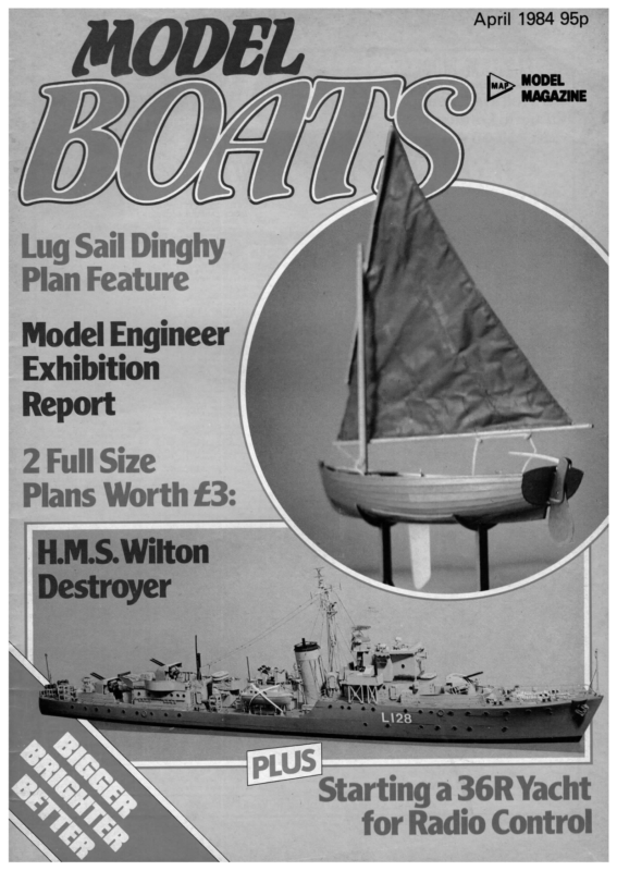
April 1984 95p Lug Sail Dinghy Plan Feature Model Engineer Exhibition Report 2 Full Size Plans Worth £3: tarting a 36R Yach for Radio Control |
ver the past few months we have discussed some aspects of building and sailing yachts, and it seems a reasonable time now to turn to putting some of what has been written into practice by actually building a yacht. Don’t get alarmed — you don’t have to build this particular one, as hopefully the step-by-step notes on construction will apply very largely to other yachts. We might digress here and there to discuss timber types and thicknesses for other models, for example, but if we follow througha fairly typical construction and fitting out sequence almost any yacht can be tackled ona similar basis. A question of size and class The first question must obviously be what size? Well, there is tremendous current interest in the 36in. Restricted class, and that is as big as most beginners would be prepared to consider. To an experienced model yachtsman, a 36 is very small, but to a novice it looks huge at home and only assumes proportion when it is afloat on a lake. Many 36s are tubby in appearance; the most elegant yachts of its length we have seen have been half size ten-raters. However, where the 12lb maximum allowed under the 36R rule provides plenty of scope for radio installation, a half size 10r will be too light, Ft d start buildin or in other words beam is not such a big influence on sail carrying-power. If the depth of keel is limited, it is natural to want to use as much beam as is allowed to increase sail-carrying ability. With length also restricted, the result is inevitably a stubby boat, the length/beam ratio being 4:1 against an average of about 5:1 for an M and 6:1 for a 10r. Since speed is influenced by waterline length, the waterline will also be as long as possible, i.e. 36in., giving a vertical stem and stern which add to the dumpy effect. However, the classic ‘formula’ for sailing speed is as long, light and narrowa hull as possible carrying as much sail as possible. The scaled-down 10 raters we have watched The frame approaching completion, with the first inwhale laminations in place. Use of a heavy vice clamped to a stool allows the all-round access. accusations of misrepresentation, it should be mentioned that the new rule introduces prohibitions on movable keels and trim tabs and, for radio, spinnakers and more than two channels, while omitting the previous prohibition on punts and prams (i.e. hulls with forward transoms). One of the aims of the revision was to keep the yachts, especially in radio form, comparatively simple and inexpensive, thus retaining an attraction for newcomers and preventing keen competitors from developing expensive trends. This intent was somewhat watered down by amendments voted through at the last AGM but that is another story. It would seem (getting back on course again!) that there might be room fora compromise between the standard 36 and something like a half-size 10r. Naturally the full allowable length and draught should be used, but a design could be narrower and lighter than the maxima, even at the expense of some sail area, without losing speed. It would give the opportunity of producing something perhaps rather better-looking, which is an important point for many tempted to move into sailing, and even if it turned out not quite competitive with the very top boats, it would still qualify to race in a class and, depending on the skill developed by the skipper, would give a good account of itself at club level. since the displacement (total weight) will be ¥, x Y, + Y, of the original. Even a 1960 10r of 36lb displacement will thus only givea 4′,]1b model at half size, and modern 10rs are likely to be about 20lb. Thus a compromise may be considered, to produce adequate displacement for radio (which many people will want to install) while avoiding the dumpiness which can arise with a 36R designed to the maximum. It must be remembered that the draught of a 36R is limited (the hull must fit in a 36 x 9 x 1lin. box) and virtually all 36s use the maximum allowed in each plane. A Marblehead or 10 rater can have the keel extended downward so that the lead is carried very low, when the stability in roll imparted by beam becomes less important, 202 (including one built) are, comparatively, long, light and narrow but carry quite a small sail area, say 300-350sq.in., which is little more than half that carried by the average 36. Yet they are noticeably faster than most 36s, especially to windward, while having a waterline of only around 30in. Now, the 36R rule lays down only maxima, not minima, in regard to the vital dimensions, and the sail area is unrestricted. The new rule — which does not differ significantly from the old except in clarifying that the rudder is not a fitting in respect of measurement and also limiting the materials from which the mast and booms can be made — was outlined in Log Book last month. Perhaps to avoid In fact, performance need not suffer. A parallel is found in the A and RA class, where for 40 years or so designers avoided being under the minimum displacement given in the design formulae because doing so involved a sail area penalty. It was proved by several boats from Clockwork Orange on that accepting such a penalty did not mean lower performance, so that now at least half the fleet in any major A or RA race will be ‘penalty boats’ and more often than not, they occupy most of the top half-dozen places. A penalty boat will have a similar waterline length and draught, but be narrower and lighter and carry less sail area than a traditional design. We seem to have said something like this a few lines back! The major difference in the two cases is the weight of the radio as a proportion of the whole. In a penalty RA, it is possibly as low as 24, per cent and almost certainly under five per cent. In a lightweight 36 it is likely to be around 10-12 per cent of the total displacement and inevitably this means a somewhat lower proportion oflead. However, since conventional radio has been fitted in 5¥,lb boats (Panache, for example), without serious interference with performance, this is not an insurmountable hurdle. Many of the author’s designs have been attempts to simplify construction Model Boats
processes, to make building a less daunting prospect to a beginner, but as part ofa general series it may be more useful to stick close to convention. Most wood yachts of round bilge form nowadays are rib and plank, often with fashion pieces for the extreme stem and stern. As this is a light 36in. model there is no reason why balsa should not be used, suitably sheathed or hardened on completion; the methods are the same but the work is easier, and the practice such a hull provides should equip a builder to tackle another, perhaps larger yacht in harder woods. As a concession to simplicity with strength, the bow fashion piece can be fairly large and laminated each side of a ply profile and longitudinal members can be laminated (or solid) spruce to provide resistance to sagging or hogging. Cost Cost? Well, let’s face the fact that you can’t build a round bilge hull for pennies these days, but the method proposed is no more expensive than any other and certainly cheaper than buying a kit or grp hull. Under £5, for sure. If you want to go cheaper, try to scrounge veneer packing from crates or ply at a woodyard and use this for planking, with scrap ply offcuts for shadows. Or, if a little extra weight is acceptable, notch in four stringers each side and double diagonal plank with card from cereal packets, as with the surprisingly successful Krispie 36R design of a few years ago. frame at each position. If you elect to do this, trace B2-B6 to the outer line of the rib in each case. : Alternatively, ply or hardboard could be used for the shadows. This involves a little more work in sawing but makes subsequent steps easier because of greater stiffness. Note that B3 and B4 can remain in the hull (as do B1 and B7) so need to be reasonable quality 4in. ply and can have cut-out areas each side of centre, which could simplify radio linkage. However, the only real purpose of leaving these two in is to support the fin, which is glued along the whole of its top to the underside of the centre deck stringer and, ifleft solid will be quite stiff enough, or could be stiffened by substituting a *,in. wide post fore and aft after removal of B3 and B4. So you can choose! B1 and B7 are /,in. balsa and the ends of the planks are glued to these; B7 is subsequently veneered outside. An important point with the shadows is that the cut-out for the deck stringer needs to be neatly cut as this stringer forms an integral part of the building jig. The shadows are slid on to it and it is placed in position supported by the thick and shallow top of B1 and a block just ahead of B7. It can be held with veneer pins or rubber bands and provides a check on the shadow height plus a firm anchorage when the shadows are glued to the building batten and the stringer. A piece of */,in. square piné was used on the original (it can be cut off a piece of doorstop) to give a fairly meaty cross-section without weighing as much as harder woods. It remains in the hull and provides a good support for centreline fittings.as well as removing the need for strong deck beams. Balsa was used for the shadows, which came out of only a fraction over one sheet of . x 3x 36in. They were a little floppy until the inwales etc. were fitted, but if fairly hard balsa (or, say */,,in.) had been used no particular floppiness would have been noticed. This assembly — batten, shadows and deck stringer — can be assembled and glued and left to dry. Use a small set-square or cut an accurate right-angle triangle from scrap wood and use it to check that the shadows are upright. A piece of in. scrap cut to the transom angle and cemented in can be used to set B7 up accurately. You may like to make a card template of B7, check that it fits, then use it to mark both sides of B7, displacing to allow for the chamfer caused by the rake. Backbone… The backbone is made from two laminations of ‘/, x */in. timber and again pine was used, cutting a planed Lin. lath down the middle. This was not so much for weight-saving as ease of working the bevels along its length, as it is fairly easy and clean to cut. Since these bevels (actually one continuous but varying bevel each side of centre) can only really be put in once the backbone is in the frame, tough and hardto-work wood is better avoided. Construction With a light hull like this, a straight and true piece of1 x 2in. planed batten was considered adequate as a building board, and furthermore it was decided to glue the shadows to it, since prising them off would not be difficult. The first step is to draw a centre-line on the wide face (you can check its straightness with a stretched thread) and mark off the positions of the shadows with a line squared off each side of the shadow thickness so that it is easy to check alignment. There is a choice for shadow material, bearing in mind that the frame needs to be rigid and reasonably strong for planking. If ¥.in. balsa is used for the shadows, this rigidity and strength will only just be adequate until the inwales and fin are in place, when it all becomes reasonably stiff. An advantage of balsa, apart from easy work, is that it is not necessary to use ribs, since the planking can be cemented to the shadows (more accurately in this case bulkheads) and when completed the centres can be cut away to leave, say a *4in. wide after planking. Photos: Vic Smeed. Continued on page 218 203 UL inside pins to hold them in place and bulldog clips/clothespegs to clamp them firmly together while the glue sets. This meant that the side faces could then be lightly planed (or filed if you prefer) and the fin slot drilled, cut and filed to finish in the vice before fitting the backbone finally to the shadows. In fact little difficulty will be experienced if soft, dry pine is used and the two strips planed to the same width and then laminated in place on the shadows. Drilling Se (only seven or eight are needed) and the two lengths of lath laminated in place, using Ss want to sit right down in a slot. Left, the transom, showing temporary block for deck stringer and rubber bands etc. holding in the unbevelled backbone, first inwhale laminations, etc. Excess is sawn off A tracing was made of the backbone and taped on a flat piece of blockboard. Veneer pins were driven in along the outside line och Above, a scoop wedge pushed under a string loop will hold the backbone if it doesn’t
bout 18 months ago I plunged into radio control aircraft and then duly bitten by the radio modelling bug, acquired a couple of electric buggies to enable me and my nineyear-old son, Richard, to carry on the fun when the weather was too bad for flying. The relatively short operating time of the buggies caused a few frustrations however, and we began to look around for something that was easy for a nine-year-old to operate, relatively crash-proof yet transportable in the car. Then the penny dropped, a yacht of course, the ideal way to use wind and weather to best advantage and yet keep mechanical maintenance to a minimum. A Plan of Action As one who thought that a Marblehead was a character from ‘Star Wars’ or a 10rater a rather nice young lady in a Dudley Moore film, I realised that things would have to be carefully planned. Our specification was a simple craft, able to be trans- ported fully rigged in the car and operating with the 2-ch. radio from one of the buggies. Lastly, the cheaper the better in case things didn’t work out. I might add that my only previous experience of model boating was a plywood electric powered free-runner that sank in the local municipal lake in 1962. The modelling grape-vine being what it is, I heard that there was someone in my home town of Swindon producing a dinghy kit. A quick phone call to Tony Workman of Workham and Capel Models elicited the information that the kits were not yet advertised or released for sale, but he’d gladly let me have one when available. Three weeks later I be- came the proud owner of a Vario model racing dinghy. First Impressions First impressions were of a large dull box without any clue to contents. Opening it revealed a well engineered and carefully packed kit, with all small components separately bagged; ply components beautifully clean cut, and a large one-piece fibreglass hull with centreboard casing moulded in. Mast and boom is a delight. Aluminium tube was already slotted with cleats rivetted in place and rigging wire ready fitted complete with hooks. The degree of prefabrication was better than expected. Making a Start The instructions suggested using Araldite but cautioned against 5-minute epoxy resins in view of the length of joints required. Being in a hurry to see something emerge I tacked the deck side frames to the main centre portion of the deck with quick-setting white glue and then fibreglassed the joint underneath. The radio was installed next, before the deck side skins were added. Although the three large recesses in the deck allow plenty of room for access I decided to take every chance to get it right. The clear instructions showed the exact position of each servo centre and the length of the servo arms required for the correct range of movement of the jib and tiller, so I made servo boxes from in. ply sheet and obechi and literally set them in a bed of epoxy; similar boxes were made for the radio receiver and batteries. The side skins of the upperworks followed, liberally taped to the edge of the hull and the deck side frames. My eagerness let me down here for when the joint dried I found that I had small gaps at the bow and stern where the skins have to be pulled down at a fairly steep angle, but a few dabs of 5-minute epoxy filled these nicely. I cleaned up all the joints and epoxy filler areas and sanded the whole upperworks. Two coats of Blackfriars polyurethane walnut stain even covered the epoxy filler areas nicely, followed by two coats of clear gloss polyurethane to complete the basic hull. The deck fittings were delightfully easy, cleats, rigging plates and all were screwed in place and holes drilled for the sail sheets and tiller linkages. The mast and beam were rapidly joined by a simple screw fixing and the mast stepped for the first time. The shrouds are easily hooked into the deck plates and tensioned by a brass bolt at the foot of the mast. Attention turned to the keel and rudder assembly. The keel is a hefty cast-iron bulb with brazed flanges that is simply epoxied onto the ply fin, and the separate rudder and tiller sandwiched by two small ply plates with a retaining bolt. Whilst these were drying, the sail fittings, hooks and eyes were stitched to the margins of the terylene sails. All accessories varnished and dried, the radio linkage was easily completed with terylene thread supplied, the keel slipped in place, secured across the centreboard with a brass pin and two rubber washers and then came the opportunity to ask something that a I used to ask my mother about a quarter of century ago; “Can I fill the bath and test my boat?’. She floats. The Big Day Richard, my son, and I rushed off to the local lake. The first happy discovery being that with the keel removed the boat can be fitted into the car fully rigged. Even so the detachable keel and folding rudder make lakeside rigging easy. We had chosen an evening when the water was flat calm and 208 Model Boats
NOOWN = LEGEND TO KIT CONTENTS PHOTO BELOW . Glassfibre hull . Centre-board/keel . . . . Mast, boom and shrouds Main deck and hatches Main deck uprights, supports Ply upper deck side skins 8. Rudder blade, stock, etc. 9. 10. 11. 12. 13. Centre-board support pieces Deck fittings for mast/shrouds Bolts, cleats, washers, etc. Fablon trim, sail numbers Instruction leaflets = the wind scarcely ruffling the tops of the trees. Even so, she glided gently along giving plenty of time to learn the response to sail settings; verdict after 1!/, hours of gentle fun; “This is great Dad!” After four or five sessions at the pond, my feeling is one of being agreeably surprised that the model does everything that I had hoped. It seems very easy to sail and responds well in all conditions from scarcely a breath of wind to noticeable gusts that take the gunwhales below the water. The kit is precisely engineered, very easy indeed to build and uses the cheapest form of radio. For a newcomer like me this is the ideal trainer combination and it is, literally, so simple that a nine-year-old can use it. Above and below, key and layout of kit components. The only parts requiring any trimming were the outer edges of the deck side skins. The mast and boom are supplied ready drilled and slotted, with cleats riveted in place and shrouds connected with hooks. Below left, the author’s son, Richard, holds the Vario in classic pose at the lakeside, Right, rear access points. All photos by the author. 209
Ge, eacat is suitable as a school project for age 12 or over, and may perhaps appeal to all those Dads who get asked “make me a boat Dad” and who have never made a boat before. Like my previous simple designs, this lively catamaran is easily constructed from readily available materials, and will cost very little. Catamarans are fast and simply made but they do suffer certain disadvantages. Firstly, if overcanvassed, they will flip over and, secondly, they can bury the lee bow and nosedive. Seacat has been carefully designed and tested to overcome these faults as far as possible. If built as shown she will perform very well. The hulls only take 15 minutes or so each to make and the whole ship no more than three or four hours (not allowing for the time plates, which can be cut from hardboard or Vin. ply. Simply sand the edges smooth and round off. Tap four panel pins through each but do not fix to hulls yet. Sails are the most difficult part to make but, usually, a kind lady can be persuaded to ‘run up’ these on a sewing machine if the Please note if hardboard is being used make sure the plates are a pair, i.e. mark out back to back on the smooth surface, otherwise you will have one smooth side and one fectly good sails can be made from poly- will see what I mean! paint takes to dry!). right amount of charm is used. If not, perthene, as described later. Stage I. Hulls Two pieces of clean softwood 2in. x lin. planed, which is actually 1%/;in. x 7,in. are required, each 24in. long. If there are knots in the wood, just try to keep them away from the ends. Cut one end at an angle of 45° and the other at about 15° as shown on plan. Each end should be sanded to a nice round section. When both ends are shaped, make a mark with a pencil ‘,in. up from the bottom at the bows (front end!). Plane the bottom in a nice curve to meet this mark, both hulls to be the same, of course. The stern end is just rounded off as shown. Now sand hulls all over to a nice smooth finish. Next, take two pieces of lin. x /,in. timber (Ramin was used on the original but ordinary laths would be suitable). Cut these to 9in. long and sand smooth. Place hulls on a flat surface 9in. apart, glue and pin crossbeams onto hulls as shown, making sure they are placed as per plan and allis square. Leave until glue is set. A /,in. hole should be drilled in the centre of the forward crossbeam to take the mast, before assembly. When the glue is dry, tap in four small staples, two into each hull, to take the rigging. Small screw eyes could be used instead of staples, if preferred, but they must be placed as shown. Next items required are the two keel rough side showing. If you do it wrong you The boat can now be painted which I always think is a most satisfying task. Before the keel plates are fitted give the whole lot a coat of clear varnish or undercoat. It is a good idea to have the crossbeams left in clear varnish or painted a different colour, so bear this in mind when undercoating. When the first coat is dry the keel plates can be pinned into position, glue being necessary. Now carefully paint in your chosen colour and set aside to dry. Stage II. Mast and rigging The mast is 2lin. long and is made from in. or %in. dowel. You could use *in. * y,in. hardwood or even thin cane. Cane is not easy to drill or fix things into though. The bottom of the mast may need to be tapered so that it fits into the hole in the crossbeam. At the top of the mast either make a sharp taper like a pencil tip or simply push a drawing pin onto the end to form a cap. The boom is next, being 10in. long and made from dowels; slightly smaller diameter than the mast if possible, but this is not too important. A fine hole needs to be drilled through the boom near the after end, or tape a wire loop to the end as per drawing inset. When it comes to rigging boats a very useful tool is an ordinary dart, dartboard variety. These have very sharp, hard points which make them ideal for making small holes. marking drilling points, starting small screw eyes and even undoing knots. If the dart happens to belong to someone else I take no responsibility! So, if you are careful, you can make a small hole through dowel without a drill. The boom is attached to the mast by means of two small screw eyes, interlinked, one screwed into the mast and the other into the boom. An alternative can be a staple in the mast and a wire loop bound, or simply taped to the boom. Obviously, the boom must be able to swing from side to side. A further screw eye must be fixed into mast front, 18in. up from deck level to take forestay and shrouds. Rigging needs to be fine and strong. Fine string or carpet thread will serve if proper rigging twine is not available. Knot a small loop in the centre of an 18in. length of twine. Pass the ends through the staples in the bows and tie tight so that the loop is in the centre between hulls. This line is called the bridle. Next, take a piece of twine about 3ft. long and tie round the mast above the top screw eye. Stand the mast in its hole and loosely tie the ends to the staples either side. Do not tighten knots yet. Tie a line from the loop in the bridle up to the screw eye in the upper mast. This line should have a hook at the top so the mast can be lowered for storage. Pull all lines tight, making sure mast is upright from front and sides and tie off permanently. Varnish mast and boom if required. Sails Cut out paper patterns as per plan and ask your chosen kind lady to make sails from any light material, cotton or nylon etc. Stress that sail patterns are finished size and allowance should be made for hems. The after (back) edges of the sail should be parallel to selvedge. If you have no luck or prefer to make your own sails from polythene it’s quite easy. Cut out sails from fine polythene (bin liners) ona flat surface with straight edge and sharp knife. Reinforce two edges with masking tape as shown. Sail should be laced to mast with strong thread, starting at the bottom. A clothespeg helps here. Just peg the top of sail to mast while you sew. Do not pull stitches tight or the sail will not be able to swing across. The job should be laced to the forestay in the same way. Both sails have to be tied top and bottoms so that they can’t slide up or down. A lineis attached from the end of the boom to a screw eye in the centre of the rear crossModel Boats
SEACAT CATAMARAN BY FRANK WILSON PLAN VIEW ® Screw eye /’\ | Ny \ yi Selvidee i java | / Keel plate 2 off 1/8″ply 21″ Y Hem or tape or hardboard (handed) Thread lacing wef | X | 4 SAIL PLAN | | i | Thread rigging Screw eyes interlocked Ends rounded Boom fitting Screw eyes N Wire bound on | TTT TTT TTT TT Twin hulls from 13″x7/8″ P.A.R. softwood (2″x1″ nominal) 10″ 3″ >} 24″ beam. This is called the ‘main sheet’ and controls the angle of the sail. Its length should be made adjustable by means of a sliding knot or adjuster. To control the jib a line is passed through an eye sewn to the bottom corner of the sail. The length of this line allows the jib to be set at various angles so its length should also be made adjustable. Each end of this line (foresheet) is attached to the staples either side. This type of jib control does away with the need for a boom along the bottom of the sail. April 1984 Paper clips can easily be straightened out what is required clearly enough. Usually, a catamaran flips over if the wind overpowers it and a capsized ‘cat’ cannot right itself. With Seacat it’s different! If the wind gusts too much the leeward hull submerges. When the wind eases up, it pops again and the boat sails on. Magic! I have not had a capsize yet with the two I have will be swift in a breeze. cheap to make. May she keep you quiet for a few hours building her and give you many hours of sailing pleasure. and used to make hooks, etc. The photographs show the catamaran fitted with lines from the stern to top of mast. These were found to be a nuisance and later removed. I think the drawing shows If the area in which you live is usually very windy it may be wise to reduce sail area by cutting off about 14in. along bottom of both sails. Even with this reduced rig Seacat made. So there she is. Seacat. Simple, fast and 211
bother. How many keen skippers do not have a sailable yacht with lapsed registration that they would not be prepared to sail in a club event? The reduction in club numbers may well be reversed by the introduction of free Public Liability Insurance to affiliated clubs. This is a direct, obvious benefit of affiliation and in many cases insurance cover arranged by individual clubs costs more than their total affiliation fee; frequently too, individual policies are more limited than that now available through Association membership. If some he Chairman’s Report, presented at the MYA AGM, is in effect a review of the Association’s position at the end of each year, plus notes on some of the less routine matters which have arisen. It customarily begins with figures on clubs and registrations, and the 1983 season proved disappointing with only 59 clubs registered (the lowest for many years) and a total of 587 registered yachts, a drop of nearly 200 in the last two years. Yet there were 189 new boats registered during the year, 105 of them in the RM class. It seems probable that one contributory cause can be found in the cost of travelling to regattas. Some clubs in less convenient geographical areas have affiliated in the past because a few of their keener members enjoyed competing and were prepared to drive considerable distances to do so. However, even a trip to a water 50 or so miles away is likely to cost £6-8 in petrol, plus entry fee, plus, if it’s a two or three day event, costs of accommodation, etc. Some clubs whose members do not sail away from home have regularly affiliated, if only so that their members can have registered boats, but with the cost of affiliation having risen a couple of years ago and a charge introduced for registration, members may clubs affiliate (or re-affiliate) because of this, there could be a small indirect benefit to the numbers of yachts on the register, but, except for those who wish to compete in other than club races, there is no real incentive to register/re-register. It is not easy to think of any incentive scheme which would encourage registration of yachts. If clubs were urged not to accept unregistered boats in club events they would — quite rightly — say that what they did in their own races was up to them. The only advantage of a high number of yachts registered is that it ensures the maximum vote for the MYA in IMYRU matters (maximum is 17 — 2 for the country and 1 per 25 registrations in the international classes, i.e. 8375 A, 10r, M and 6), apart from the statistical clout of a large number of boats in any negotiation/publicity, but this is not likely to cause a stampede of ordinary club members wanting to register. Financial motivation As in most aspects of modern life, clear feel that they do not need to pay affiliation and registration fees to direct personal benefit is the most effective motivation. It was the convention or habit to get yachts registered or re-registered, but introduction of a registration fee caused people to examine the habit, and clearly many decided they need not conform to it. If registration were to be made free again, the number of yachts would still remain water. In the same way, many owners has been broken. If — and it is not continue to enjoy themselves on the local liked to keep all their boats in sailing condition and on the current register, which cost them only postage and a few minutes of time, but now they don’t Continued from page 203 and slotting for the fin is easy if drill holes are made every ¥in. and the material between cut out with a razor blade or modelling knife. It pays while waiting for the glue to dry to cut out and fit the fin, since once this is glued in the whole frame loses its tendency to ‘rhomboid’ backward or forward. Use exterior grade ply, slightly thicker than \.in. if possible. 4mm is ideal, but it is always possible to stick a layer of thin ply or balsa each side on that part outside the hull if you use 3mm and later decide that it needs to be a fraction stiffer. It is worth shaping the leading and trailing edges (the worst job in building a yacht!) before fitting permanently in place. While cutting ply you might as well trace and cut the stempiece, which can be laid into place and lightly glued. The balsa blocks to be added later will ensure its security and alignment, provided B1 is set true. 218 below what it could be, because the habit suggested that it is necessarily practical — ownership of a registered yacht or yachts allowed the owner a discount on his affiliation fee of, say, 20% per yacht, Next fit the inwales, which are two laminations of !/, x /,in. spruce each side. Fit the first pair, both at the same time, gluing to B1 and B7 and lightly gluing to the other shadows. They can be pinned in place, or supported in their notches by pins and rubber bands until the glue has dried. It is possible to set the whole frame up vertically in the vice, which simplifies work, but make sure that it is secure. At the second stage of this process the prototype leapt out of the vice, crashed on the floor and all sprang apart… Once dry, the second lamination can be glued to the first and held with bulldog clips or clothespegs till dry. The frame is now reasonably rigid and the bevels can be carved and filed or sanded along the backbone and inwales. The latter should be flush to the shadows but the backbone should remain ¥/,.in. proud. …and ribs The ribs are sliced off scrap !/;,in. (.8mm) ply; ifa piece of ply is bought for the deck or if a yacht insurance scheme, free to registered vessels, was to be introduced, registrations would probably climb again, because a direct benefit could be seen. The Chairman’s Report reflects that since the 1920s nearly 9,000 boats have been officially registered and that there must be many more than those holding current certificates still sailable. Unfortunately, if clubs were asked to tot up the number of once-registered models owned by their members (which would be an interesting and potentially useful statistic) it is doubtful if more than two or three clubs would respond. Pity, because to be able to say that (say) 3,200 registered models exist, nearly 600 of which have current racing certificates, gives a far better idea of the Association’s make-up. The present registered total means less than one boat per two members, which is not a true reflection of things. Sports Council This sort of statistic might possibly have made a little difference to the Chairman’s negotiations in respect of grant aid from the Sports Council. Recent changes in personnel seem to have resulted in less sympathy for the modelling cause and, it might appear, more support for the vested interests who have so firm a grip on this slice of public money. The Report (to get back to it) states that we shall continue to press. Other points from the Report cover the increasing number of incorrectly completed championship entry forms (the Racing Secretary will be stricter, incomplete forms will be returned and the closing date will not be extended), the Royal Garden Party, exhibition participation, the first R36R Championship, and model yachting for the disabled. This last arises from the Association’s membership of the Water Sports Division of the British Sports Association for the Disabled, who feel that radio sailing is an ideal interest and activity for those with little or no mobility. Birkenhead, Leicester and Guildford have already encouraged disabled people to take part and it is hoped that more clubs will follow. and the deck roughly traced on to it, spare areas will be obvious and a steel rule and strong knife can be used to cut strips a full Yin. wide. As the shadows are drawn each rib passes over the backbone and therefore, to ensure a flush surface, the backbone should be notched ¥/,,in. deep at each rib position. Alternatively, the ribs may be cut and butted to the backbone with just a touch of glue. At the inwales it is normal practice to lay the ribs over the inwale and then fill the gap which would otherwise exist between gunwale plank and inwale by glueing further strips of !/;,in. ply along the inwale between the ribs. If it is preferred to notch the inwales so that the ribs lie flush it would be advisable to increase the inwale size by using one 4 x /,in. and one 9, * Y;in. each side and the outer edge will need to be ¥,,in. proud of the shadows. Now check the whole frame carefully for truth and symmetry and adjust where necessary, as this is the last chance to make corrections before planking, which will be dealt with next month. Model Boats


